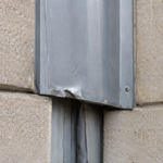
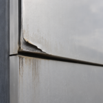
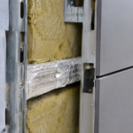
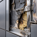
- Water intrusion at expansion joints is routinely misattributed to cladding sealants because the actual entry point travels 18 to 36 inches before appearing indoors.
- Movement capacity assumptions based on rule-of-thumb calculations routinely underestimate actual differential movement in mixed-use podium construction.
- The substrate transition zone between the cover flange and dissimilar cladding sits outside every subcontractor’s warranty scope and inside nobody’s specification.
- Three-sided sealant adhesion at the flange perimeter violates ASTM C1193 and is built correctly from a detail that is fundamentally wrong.
- Early building envelope commissioning with ASTM E2128 water testing at joint locations prevents the misattribution cycle that allows these failures to repeat.
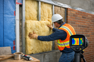
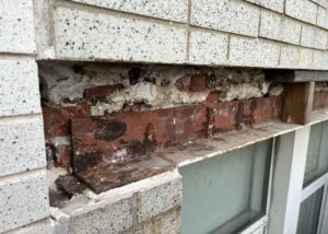
A forensic investigation on a four-year-old mixed-use podium building in the Upper Midwest reveals water-stained gypsum sheathing and corroded steel framing at every expansion joint location along the north facade. The joint covers show no visible damage.
The sealant beads appear intact. The original installer’s warranty is still active.
Tracer dye testing confirms the water entry point is not the joint cover itself; it is the unaddressed substrate transition gap between the cover anchor flange and the dissimilar cladding substrate on each side. This scenario is not an outlier.
It is the predictable result of a design assumption chain that breaks down before the first winter cycle is complete.
The Movement Capacity Assumption and Where It Comes From
Design teams routinely size expansion joint covers using rule-of-thumb thermal movement calculations without performing building-specific differential movement analysis that accounts for material diversity within the facade plane. The standard shorthand of plus or minus one inch total movement for a nominal joint width gets applied to buildings where the actual movement demand has never been calculated.
That shorthand fails on mixed-use podium construction almost every time.
AISC Design Guide 3 and ASCE 7-22 §12.12. 3 provide explicit frameworks for calculating inter-story drift and seismic relative displacement demand for cladding and facade elements.
Both frameworks are routinely bypassed at the schematic design phase, when joint locations and cover selections are being locked in by the architect before the structural engineer has completed the lateral analysis. The result is a joint cover selected from a catalog cut sheet based on nominal joint width, not calculated movement demand.
On projects where the structural engineer does complete a drift analysis, those values rarely get communicated back to the architect in a format that informs cover selection. The structural drawings note maximum allowable story drift as a percentage of floor height.
The architectural specification references a nominal joint width in inches. Nobody converts one to the other.
Mixed-use podium construction compounds this problem in ways that are specific and quantifiable. A concrete podium structure, light-frame upper floors and ACM or curtainwall cladding panels all carry distinct thermal coefficients of expansion and distinct seismic response characteristics.
Those values must be summed across the building height, not averaged. The differential movement between a concrete podium at grade and a cold-formed steel framed floor five stories above it can exceed the rated capacity of a standard cover assembly by 30 to 50 percent under IECC Climate Zone 6 temperature swings.
In Minneapolis, that temperature swing spans roughly 130 degrees Fahrenheit between design winter minimum and design summer maximum. At a coefficient of thermal expansion of 6.5 millionths per inch per degree Fahrenheit for concrete and 9.
9 millionths for aluminum framing, the cumulative differential across a 60-foot building height is not a rounding error. It is a calculable value that the design team chose not to calculate.
The cover assembly manufacturer’s rated movement capacity is a laboratory value. Installed capacity is reduced by anchor spacing deviations, substrate flatness tolerance and field-bent flanges.
That distinction is rarely communicated during submittal review and it is never enforced in the field. A cover assembly rated for plus or minus one inch of movement at 12-inch anchor spacing loses meaningful capacity when field crews install anchors at 18 to 24 inches because the intermediate framing does not align with the cover flange holes.
The flange deflects between anchor points under load, the center-span contact with the substrate is lost and the sealant at the flange perimeter bridges a gap it was never sized to span.
How Exterior Wall Plane Joints Differ From Floor and Roof Joints
Exterior wall plane joints are subject to simultaneous biaxial movement: in-plane shear from thermal cycling and seismic drift combined with out-of-plane loading from wind-driven rain at static pressures that floor joint covers are never designed to resist. This loading combination is not hypothetical.
It is the baseline service condition for any vertical joint on an exposed facade. A floor joint cover in a conditioned interior corridor experiences foot traffic and minor thermal cycling.
A wall plane joint cover on a north facade in Climate Zone 6 experiences wind pressures exceeding 20 psf during design storm events, freeze-thaw cycling that can occur 40 or more times per year at the substrate interface and UV degradation that reduces sealant elongation capacity by 30 to 40 percent within the first three years of service. These are categorically different performance environments and the specification rarely acknowledges that distinction.
Wall plane covers must function as both a movement accommodation device and a weather barrier component. These two performance requirements are rarely coordinated in the specification.
The architectural specification section for expansion joint covers typically lives in Division 07, adjacent to sealants and weatherproofing, while the structural movement criteria live in the structural drawings. Neither document references the other.
The result is a cover assembly specified for aesthetics and nominal joint width, with weather barrier performance assumed but never specified. Project manuals reviewed in forensic practice consistently show the expansion joint cover section referencing the manufacturer’s standard detail for flange termination, with no performance language requiring air barrier continuity, water control layer integration or pressure-equalized drainage at the cover perimeter.
Gravity drainage is not available at vertical joints the way it is at horizontal joints. Any water that enters the cover-to-substrate interface on a vertical wall plane must be managed by pressure equalization or redirected by flashing.
Neither approach is typically detailed. The cover flange sits against the substrate face, the perimeter gets a sealant bead and the detail is called complete.
At horizontal joints, water that infiltrates the cover-to-substrate interface drains by gravity to the next horizontal termination point. At vertical joints, that same water is driven laterally and inward by wind pressure differential.
The geometry that makes a floor joint forgiving makes a wall joint unforgiving and the same cover assembly specification gets applied to both conditions without modification.
ASTM E331 is the most commonly cited test standard for adjacent cladding assemblies, but it is not directly applicable to the joint cover assembly as a standalone component. ASTM E1105 addresses field testing of installed fenestration and cladding under cyclic pressure, but neither standard establishes a testing protocol for the joint cover flange-to-substrate interface specifically.
That testing gap means the most vulnerable transition in the assembly has no defined performance benchmark in the contract documents. A specifier who wants to establish a performance requirement for this interface has no published standard to cite.
The result is that the interface gets no performance requirement at all, which is a different outcome than an interface with an imperfect performance requirement.
Anatomy of the Substrate Transition Detail: The Actual Leak Location
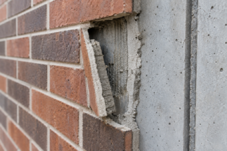
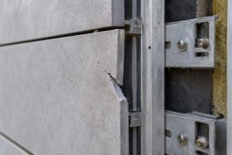
The substrate transition zone is the interface between the expansion joint cover anchor flange and the dissimilar substrate material on each side of the joint. On a typical mid-rise facade, this zone spans two to four inches on each side and terminates against an ACM panel system receiver, an EIFS base coat edge termination or a masonry veneer edge condition.
In the majority of construction documents reviewed in forensic practice, this zone is addressed by a single field-applied sealant bead. That is not a detail.
That is an assumption.
Three failure mechanisms concentrate at this zone. First, differential movement between the cover flange and the substrate exceeds the elongation capacity of the field sealant.
A polyurethane sealant rated at plus or minus 25 percent joint movement will fail cohesively when the flange moves at a rate and magnitude the sealant joint geometry cannot accommodate. Second, the substrate surface is not continuous or planar at the termination edge, creating a three-sided sealant joint condition that cannot develop adhesion on the fourth face.
Third, air pressure differential across the assembly drives water laterally behind the cover flange before it reaches the sealant line. The sealant never contacts the water because the water bypasses it entirely.
The three-sided joint condition is the most underappreciated failure mode in this assembly. ASTM C1193-16 §5.3 explicitly identifies three-sided adhesion as a cause of cohesive failure and requires a backer rod to prevent bond to the back face of the joint.
Construction documents routinely show sealant applied directly into a reglet or receiver channel without a backer rod, creating exactly the condition C1193 prohibits. This is not a field error.
It is a specification and detail error that gets executed correctly by the installer. The installer follows the detail.
The detail is wrong. The warranty claim goes to the installer anyway because the sealant failed and the installer applied the sealant.
Forensic tracer dye results consistently show dye migration paths that originate at the flange-to-substrate interface and travel horizontally behind the cladding substrate before appearing at interior surfaces. That travel path crosses cladding panel boundaries.
It crosses sealant joint lines. It appears to originate from the adjacent cladding system because the visible manifestation point is 18 to 36 inches from the actual entry point.
Investigators performing visual-only assessments document the nearest cladding seam as the probable source. The expansion joint transition never gets tested.
In one documented case on a six-story EIFS-clad building in Ohio, tracer dye injected at the expansion joint cover flange appeared at an interior wall surface 28 inches away, directly behind an EIFS panel joint that had been previously repaired twice under warranty. The panel joint repair resolved nothing because the panel joint was not the source.
The repair contractor documented successful sealant replacement and closed the warranty claim. The building continued to leak through the same winter cycle.
Why Forensic Investigations Misattribute the Source
Water entry at the substrate transition zone typically travels 18 to 36 inches laterally before manifesting at an interior surface. That travel path crosses cladding panel boundaries, which causes investigators performing visual-only assessments to identify the nearest cladding seam or sealant joint as the probable source.
The misattribution is not careless. It follows from the physical evidence as it presents itself without systematic testing.
Confirmation bias compounds the problem. After three to five years of UV exposure, virtually every field-applied sealant joint on an exterior facade shows some degree of surface crazing or adhesion loss.
That condition is visible, documentable and defensible as a probable cause. The expansion joint cover transition is not visibly degraded.
The cover itself looks fine. Investigators document what they can see and stop there.
The investigator who writes “sealant joint failure at panel seam, probable water entry” in a forensic report is not fabricating evidence. The sealant joint is degraded.
The documentation is accurate. The causal conclusion is wrong and the wrong conclusion drives the repair scope, which fails to resolve the problem, which generates a second forensic investigation two years later that reaches the same wrong conclusion.
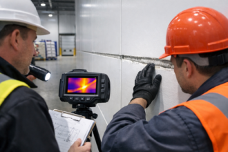
Proper forensic protocol requires sequential water testing per ASTM E2128 (Standard Guide for Evaluating Water Leakage of Building Walls), which establishes a systematic methodology for isolating water entry zones through progressive testing rather than visual assessment alone. ASTM E2128 requires that each potential entry zone be tested independently and eliminated before moving to adjacent zones.
Applied correctly, this protocol requires testing the expansion joint cover flange perimeter with tracer dye injection before testing any adjacent cladding zone. That sequence is rarely followed in standard forensic practice.
The more common sequence is visual assessment, photographic documentation of visible sealant degradation, repair recommendation and close-out. ASTM E2128 testing is specified in the contract when the owner has retained a building envelope consultant with commissioning authority.
It is not specified when the forensic investigation is managed by the general contractor’s insurance carrier, which is the more common arrangement on four-year-old buildings still within the general warranty period.
Insurance and warranty claim structures create a direct incentive for misattribution. The cladding subcontractor and the joint cover installer are separate parties with separate warranty documents.
The path of least resistance for the general contractor is to assign responsibility to the cladding sealant, which is visibly degraded, easily photographed and covered under a separate subcontract. The expansion joint cover installer’s warranty remains intact because the cover assembly itself has not failed.
The substrate transition detail was never part of anyone’s scope. The cladding subcontractor’s warranty covers sealant joint performance within the cladding system.
The expansion joint cover installer’s warranty covers the cover assembly. The air barrier subcontractor’s warranty covers the membrane within the air barrier system boundary.
The substrate transition zone sits at the intersection of all three scopes and is explicitly excluded from each one. That exclusion is not accidental.
It is the direct result of scope boundaries written to protect each subcontractor from liability for adjacent work and it leaves the highest-risk zone in the assembly with no warranty coverage and no responsible party.
The Specification Gap That Makes This Inevitable
The substrate transition detail fails in the documents before it fails in the field. Division 07 expansion joint cover specifications reference the manufacturer’s installation instructions for anchor spacing and flange termination, but manufacturer installation instructions are written to protect the manufacturer’s product warranty, not to address the water control layer continuity across the transition zone.
Those are different documents with different objectives. A manufacturer’s installation instruction that specifies “apply compatible sealant at flange perimeter” has discharged the manufacturer’s obligation to the installer.
It has not addressed the building’s obligation to keep water out of the wall assembly. The specifier who defers to manufacturer instructions at this detail has transferred the design decision to a party with no design liability and no knowledge of the specific substrate conditions on that project.
Water control layer continuity at the expansion joint cover transition requires explicit coordination between the joint cover specification, the air barrier specification and the cladding system specification. In practice, each specification section is written independently by a different consultant or by the spec writer working from a master specification without cross-referencing the adjacent assemblies.
The joint cover section says “terminate flanges per manufacturer’s instructions and seal with compatible sealant. ” The air barrier section shows the WRB terminating at the joint edge.
Nobody specifies what connects them. The air barrier subcontractor installs the membrane to the joint edge and stops, because the specification says to stop there.
The joint cover installer applies sealant to the flange perimeter and stops, because the specification says to stop there. The gap between those two termination points is two to four inches of uncontrolled substrate that neither subcontractor owns and neither specification addresses.
That gap is where the water enters.
The detail drawing typically shows a section cut through the joint mid-span, where the cover is performing as intended. The flange termination condition at the substrate transition is either not shown or shown schematically without dimensions, material callouts or sequencing notes.
A contractor reading that detail has no basis for understanding that the transition zone is the highest-risk location in the assembly. Installation sequencing is particularly consequential at this detail.
The WRB membrane must be installed and lapped onto the back face of the cover flange before the cladding substrate is installed over it. If the cladding substrate is installed first, the WRB lap is physically inaccessible and the transition cannot be executed correctly regardless of the installer’s intent.
That sequencing dependency is never noted on the detail drawing and is never addressed in the specification. The result is that the cladding substrate goes in first on nearly every project, because that is the logical construction sequence when no one has told the framing crew otherwise and the WRB transition gets executed as a surface-applied sealant bead against an already-installed substrate edge.
That is the condition that fails.
What a Defensible Transition Detail Actually Requires
A substrate transition detail that controls the four control layers through the expansion joint cover flange termination requires five specific elements. The WRB or air barrier membrane must lap onto the back face of the cover flange by a minimum of two inches and be adhered, not just draped.
A compressible foam backer rod must be installed at the flange-to-substrate interface to prevent three-sided sealant adhesion per ASTM C1193-16 §5.3. The sealant joint geometry must achieve a width-to-depth ratio between 2:1 and 1:1 with confirmed substrate compatibility. The cover flange anchor spacing must be specified at a maximum interval that maintains continuous substrate contact under the design movement range.
And the transition detail must be shown on a large-scale drawing with explicit material callouts, not referenced to a manufacturer’s standard detail.
None of these elements are expensive. All of them require coordination that the standard design process does not currently produce.
The WRB lap onto the cover flange back face requires that the cover flange be installed before the WRB, which requires that the structural substrate be complete and the joint gap be established before the water control layer sequence begins. That sequencing constraint has to appear in the specification and on the drawing or it will not happen in the field.
The backer rod at the flange-to-substrate interface adds material cost measured in cents per linear foot. The large-scale detail drawing requires two to four hours of drafting time.
The sealant compatibility confirmation requires a written statement from the sealant manufacturer, which costs nothing. The anchor spacing specification requires the engineer of record to calculate a maximum spacing based on the design movement range, which is work that should already be happening as part of the movement capacity analysis described in the first section of this article.
The five elements are not independent requirements. They are the downstream outputs of a design process that starts with a calculated movement demand and ends with a construction document that tells every subcontractor exactly what to build at the highest-risk location in the assembly.
The Inspection Protocol That Changes the Outcome
The buildings that avoid this failure pattern share one characteristic: a building envelope commissioning agent with authority to review transition details at the schematic design phase, not during submittal review. By the time submittals arrive, the joint locations are fixed, the cover type is selected and the transition condition is already determined by the cladding system geometry.
Submittal review catches material conflicts. It does not catch the detail gaps that produce the failures described here.
A building envelope commissioning agent reviewing the schematic design package can identify the substrate transition condition before the detail is drawn, require that the design team produce a large-scale transition detail as part of the design development deliverable and establish the sequencing constraints in the specification before the project goes to bid. That intervention costs one to two hours of review time at the schematic phase.
The forensic investigation it prevents costs 40 to 80 hours of field testing, documentation and report preparation, plus the repair costs that follow from it.
Specify ASTM E2128-compliant water testing at a minimum of two expansion joint locations during building envelope commissioning, with tracer dye injection at the cover flange perimeter as the first test sequence before any adjacent cladding zone is tested. Require that test results be documented with dye migration photography and that the expansion joint transition be explicitly cleared before the cladding sealant is evaluated.
The two test locations should be selected to represent the highest-risk conditions on the building: one location at a substrate transition between dissimilar cladding systems and one location at a floor-level horizontal joint where the vertical cover meets a horizontal sill condition. Those two locations will expose the most common failure modes.
If both locations pass, the probability that the remaining joint locations are correctly installed increases substantially, because the same crew installed all of them under the same supervision and the same specification. If either location fails, the failure mechanism identified at that location applies to every joint on the building and the repair scope can be defined before the building is occupied rather than four years after the warranty expires.
That protocol will not prevent every failure, but it will prevent the misattribution that allows these failures to persist through multiple warranty cycles without correction. Four years from now, the building you are reviewing today should not be the case study in someone else’s forensic report.