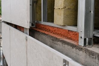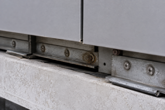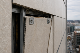
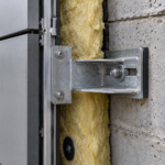

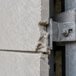

- Backed stone soffit panels installed in the early-2000s were routinely anchored using shear-dominant calculations that failed to account for sustained gravity tension.
- A 2019 forensic investigation confirmed anchor pull-out as the cause of three 80-lb granite panel displacements after only 17 years of service.
- Concealed attachment systems eliminate visible distress signals meaning progressive anchor failure can develop silently for a decade before displacement occurs.
- Differential thermal expansion between aluminum composite backing and granite creates cyclic shear demand that accelerates fatigue cracking at anchor contact surfaces.
- Current specifications still lack explicit pull-out demand methodology for horizontal soffit applications and project-specific engineering analysis must fill that gap.
Backed Stone Soffits: Anchor Geometry Risk
Why Soffits Are Not Just Upside-Down Facades
A 2019 forensic investigation of a mixed-use tower in the Mid-Atlantic region documented the sudden displacement of three 80-lb granite soffit panels from a parking structure canopy, with anchor pull-out confirmed as the primary failure mode after only 17 years of service. Post-removal inspection revealed that the original shop drawings had specified anchor embedment depths and edge distances calibrated for vertical facade loading, not the sustained tensile demand imposed by gravity on a horizontal soffit.
The incident triggered a portfolio-wide recertification review across 14 similar properties and exposed a calculation gap that many facade engineers are still encountering today.
The geometry of the load path changes fundamentally at the soffit plane. On a vertical facade, gravity acts parallel to the panel face and anchors resist primarily in shear.
Wind load introduces a perpendicular component, but that demand is intermittent, reversible and bounded by the design wind event. On a soffit, gravity acts perpendicular to the panel face at all times.
Anchors carry sustained direct tension for the full service life of the assembly. That distinction is not subtle.
It is categorical.
Wind uplift on a vertical facade is a transient event. Gravity tension on a soffit anchor is not.
Thermal cycling and moisture infiltration compound creep in anchor components under sustained tensile load in ways that shear-loaded anchors simply do not experience at the same rate or through the same mechanisms. The difference in failure timeline reflects this directly.
A shear-dominated anchor that is undersized tends to show distress through visible panel racking or joint displacement. A tension-dominated anchor that is creeping gives no comparable signal.
ASCE 7-22 Section 30.13 addresses pressure coefficients for components and cladding on canopies and overhangs. It does not prescribe anchor geometry checks specific to sustained gravity tension in stone soffit assemblies.
That gap is where failures originate. Engineers who apply Section 30.13 pressure coefficients correctly but then size anchors using shear-dominant calculation templates have addressed the wind demand while leaving the gravity demand miscalculated.
The code does not catch that error because the code was not written to catch it. The engineer of record is responsible for recognizing the loading orientation change and adjusting the anchor design methodology accordingly.
In the early-2000s construction cycle, that recognition was inconsistent at best.
How Concealed Anchors Were Specified in Early-2000s Stone Soffit Systems
Three anchor types dominated stone soffit installations during the early-2000s construction cycle: kerf-and-clip systems, undercut mechanical anchors and epoxy-set threaded rods grouted into the stone back-face. Each carries a distinct vulnerability profile in a tensile loading environment.
Kerf-and-clip systems transfer load through bearing between a metal clip and the walls of a routed slot in the stone edge or back face. In vertical applications, the clip resists shear.
Rotated to a soffit, the same clip must now resist the panel weight in direct tension against the kerf wall bearing surface. The geometry was not designed for that orientation.
Undercut anchors perform better in tension by engaging a mechanical interlock within the stone body, but their pull-out capacity is highly sensitive to the quality of the undercut geometry and the stone’s tensile strength perpendicular to bedding planes. Epoxy-set threaded rods depend entirely on the bond between adhesive and stone, a bond that degrades under sustained load, moisture cycling and elevated temperatures.
Shop drawing review practices of that period frequently delegated anchor sizing to stone fabricators. Those fabricators calibrated their calculations to vertical panel weight plus design wind pressure.
Sustained overhead tension was not in their calculation template. The design professional of record often reviewed shop drawings for dimensional compliance and general conformance with the contract documents without independently verifying that the anchor sizing methodology was appropriate for a soffit orientation.
That review gap was systemic, not isolated to individual projects.
Concealed attachment was specified for aesthetic reasons on high-visibility soffits: hotel entry canopies, retail arcades and transit shelters. That decision eliminated the redundancy that exposed mechanical systems provide through visible distress signals.
A visible clip that has begun to deform tells you something. A concealed anchor that is creeping gives you nothing until the panel moves.
The aesthetic preference for clean, uninterrupted stone ceilings was legitimate, but it carried an engineering cost that was not explicitly acknowledged in the specification or the risk management framework for those projects.
Backed panels added composite stiffness but introduced a new problem. Differential thermal movement between the aluminum composite or fiberglass backing and the stone face was rarely modeled at the anchor interface.
ASTM C1242, the standard guide for dimension stone attachment systems, was in its 2001 edition during that installation period. That edition contained limited guidance on soffit-specific anchor geometry and no explicit pull-out demand calculation methodology for horizontal applications.
Fabricators working to that standard had no normative reference to flag the calculation gap and specifiers who cited ASTM C1242 as the governing standard for the attachment system may have believed the standard covered the soffit condition more completely than it did.
The Anchor Geometry Assumptions That Break Down at the Soffit Plane
The concrete cone breakout model in ACI 318-19 Chapter 17 provides the most useful geometric framework for understanding what happens to anchor capacity when loading direction changes, even when the substrate is stone rather than concrete. In a vertical application, the critical failure cone develops under lateral demand and projects outward from the anchor into the substrate material.
Edge distance and embedment depth are sized to ensure the projected failure area is sufficient to engage enough material to resist that lateral force.
Rotate that assembly ninety degrees to a soffit orientation and the failure cone reorients with it. The same embedment depth that provided adequate projected area in shear now produces a shallower effective cone in the direction of tensile demand.
Edge distances that were acceptable for shear interaction may now place the failure cone in conflict with panel edges or adjacent anchor zones. The projected area calculation must be reoriented entirely and in most early-2000s soffit packages, it was not.
A 1.5-inch embedment depth that satisfied shear demand in a 3/4-inch-thick granite panel may produce a tensile breakout cone that intersects the panel back face before developing full projected area, effectively reducing the available failure surface to a fraction of what the calculation assumed.
Anchor spacing compounds the problem. Minimum spacing rules derived from shear interaction do not account for the additive tensile demand when adjacent anchors share a gravity load with no load redistribution path available if one anchor softens or creeps.
In a vertical facade, a partially engaged anchor sheds load laterally to its neighbors through the panel stiffness. In a soffit, that same redistribution mechanism works against the assembly because the neighboring anchors are already carrying their full share of gravity load.
When one anchor in a four-point soffit panel loses engagement, the remaining three anchors must carry a load they were not sized to handle and the progression to full panel displacement can be rapid once that redistribution begins.
The backing bond-line creates a hidden load path assumption. Load is often assumed to transfer from the stone face through the adhesive bond to the backing and from the backing to the anchor.
If that adhesive bond degrades through UV exposure, moisture cycling or thermal fatigue, the full panel weight transfers directly to the stone-to-anchor interface at a geometry the anchor was never sized to carry alone. This load path assumption is rarely stated explicitly in shop drawing submissions, which means the reviewing engineer may not recognize that the anchor sizing is conditional on the backing bond remaining intact for the full service life of the assembly.
Kerf geometry tolerance stack-up is the most underappreciated failure initiator in this category. Fabrication tolerances in kerf depth and clip engagement length are acceptable for shear loading because bearing area is generous in that orientation.
Under tension, the effective bearing length of the clip against the kerf wall is the only resistance mechanism. Published test data indicates that a 2mm undercut in kerf depth can reduce pull-out capacity by 30 to 40 percent.
That tolerance range is well within normal fabrication variation for stone cutting operations, which means panels that passed dimensional inspection at the fabrication shop may have arrived at the job site with anchor capacity already reduced below the design assumption. ASTM C1354 provides test methods for strength of individual stone anchorages, but test specimens are typically oriented for shear loading.
Direct tension pull-out data for kerf systems remains sparse in the published literature and the data that does exist tends to come from manufacturer qualification testing rather than independent research, which limits its applicability to field conditions with real fabrication variability.
Progressive Pull-Out: Why the Failure Mode Is Silent Until It Isn’t
Progressive pull-out does not look like brittle fracture. It is the sequential softening of anchor engagement under sustained load, where micro-displacement at the anchor-stone interface accumulates incrementally without visible panel movement until a displacement threshold is crossed and the remaining engagement length can no longer carry the load.
By the time the panel moves, the failure has been developing for years.
Creep in epoxy-set anchors under sustained tensile load is well-documented in the adhesive anchor literature. ICC-ES AC308 acceptance criteria require creep testing under sustained load for adhesive anchor qualification.
The test protocol involves monitoring displacement under a defined percentage of rated load over a specified duration. The gap is that this protocol was not universally applied to stone soffit installations in the early-2000s period and the test durations used for qualification bear limited relationship to a 20-year field service life under variable temperature, moisture and load conditions.
AC308 creep testing is conducted at controlled laboratory temperatures. Field conditions on a south-facing parking canopy soffit in a hot climate can push anchor temperatures well above those laboratory baselines and epoxy creep rate increases nonlinearly with temperature.
An adhesive anchor that qualifies under AC308 at 110 degrees Fahrenheit may be creeping at a materially higher rate in a field installation where summer surface temperatures on a dark stone soffit regularly exceed 140 degrees Fahrenheit.
Concealed attachment eliminates the visual distress indicators that would alert a building operator or inspector to developing anchor movement. A visible clip that has deflected, a panel that rocks under hand pressure, a grout joint that has opened unevenly: these are diagnostic signals in an exposed system.
A concealed system provides none of them. Building maintenance staff who perform routine visual inspections of soffit surfaces are looking at the stone face, not the anchor zone.
They have no line of sight to the condition that matters and no training framework that would help them interpret what they are seeing even if partial access were available. The inspection gap is structural, not a failure of diligence.
Seasonal thermal cycling drives ratcheting. Panels expand and contract with temperature and each cycle can advance anchor displacement incrementally as the clip or rod moves against the stone contact surface.
In cold climates, freeze-thaw of moisture that has infiltrated into kerf joints accelerates this mechanism by introducing hydraulic pressure directly at the bearing interface. A kerf joint that has accumulated even a thin film of water at the clip bearing surface will experience ice expansion pressure of approximately 2,000 psi during a freeze event, applied directly to the stone material at the most geometrically sensitive point in the anchor system.
The OSHA 29 CFR 1926 general duty obligations for falling object hazards apply once a panel is identified as at risk, but the regulatory framework does not help you identify the at-risk condition before displacement occurs. The liability exposure for building owners and engineers of record is therefore concentrated in the period between when the failure process begins and when it becomes detectable, a period that the evidence from forensic investigations suggests can span a decade or more.
What a Recertification Assessment Must Actually Examine
A condition assessment for a backed stone soffit assembly from this era cannot rely on visual inspection of panel surfaces. The failure mechanisms described above are invisible from below.
A credible assessment requires access to the anchor zone.
That means selective panel removal at statistically representative locations, with removal sequence prioritized by exposure, age and any available original documentation. When you pull a panel, you are looking at kerf wall condition, clip engagement length, any evidence of epoxy bond degradation and the condition of the backing adhesive at the perimeter and field of the panel.
You are also measuring what is actually there against what the shop drawings said should be there. In a significant percentage of the forensic investigations I have been involved with, those two things do not match.
Kerf depths that were specified at 20mm have been found at 14mm. Clip engagement lengths that were shown at 25mm on the shop drawing have been found at 16mm in the field.
Those discrepancies are not installation defects in the traditional sense. They are the product of fabrication tolerances that were never evaluated for their effect on tensile pull-out capacity, because the original design did not recognize tensile pull-out as the governing demand.
Pull-out testing in place using ASTM C1354 procedures, adapted for tensile orientation, provides direct capacity data. That data should be compared against a recalculated demand that correctly accounts for sustained gravity tension, not the shear-dominant calculation that was used originally.
The recalculated demand must include a load duration factor appropriate for sustained tensile loading in stone, which ASTM C1242 addresses in general terms but which requires project-specific judgment to apply correctly. If the original engineer of record is not available to perform that recalculation, the recertification engineer must reconstruct the original design intent from shop drawings and then evaluate it against current understanding of soffit anchor geometry demands.
That reconstruction process is time-consuming and frequently reveals that the original design intent was never fully documented in the shop drawing package, leaving the recertification engineer to make conservative assumptions about what was and was not accounted for.
Documentation of differential movement between the stone face and the backing is achievable through close-interval photogrammetry or manual probe inspection at panel edges. Delamination of the backing from the stone face is a leading indicator of impending full load transfer to the anchor interface.
Panels that show perimeter delamination but no anchor distress are in a transitional condition where the anchor system is beginning to carry load it was not sized to handle. Those panels warrant immediate further investigation and should not be returned to service without engineering evaluation, even if they appear visually intact from below.
Photogrammetric documentation at six-month intervals can establish whether delamination is progressing, which informs the urgency of remediation planning and provides defensible documentation of the assessment process if a panel displacement event occurs during the evaluation period.
The Backed Panel Differential Movement Problem
The backing in a composite stone soffit panel does more than add stiffness. It changes the thermal mass distribution of the assembly, alters the moisture exposure profile of the stone back face and introduces a second material with its own coefficient of thermal expansion into a system where the anchor geometry was designed around stone properties alone.
Aluminum composite backing expands at roughly twice the rate of granite per degree of temperature change. The coefficient of thermal expansion for aluminum is approximately 13 x 10-6 per degree Fahrenheit, compared to roughly 4 to 8 x 10⁻⁶ per degree Fahrenheit for granite depending on mineralogy and orientation.
Over a 100-degree Fahrenheit seasonal temperature swing, that differential movement across a 24-inch panel dimension is measurable and cumulative at the adhesive bond line. Fiberglass backing performs better in this regard but introduces its own moisture absorption characteristics that affect long-term bond integrity.
Fiberglass reinforced polymer panels can absorb between 0.1 and 0. 5 percent moisture by weight depending on resin system and laminate quality and that absorbed moisture changes the dimensional behavior of the backing in ways that are difficult to predict over a multi-decade service life.
The anchor interface sees this differential movement as a cyclic shear demand superimposed on the sustained tensile gravity demand. The combination is more damaging than either loading alone.
Fatigue at the stone contact surface around a kerf or undercut anchor progresses faster under combined loading than under pure tension and the interaction is rarely modeled in standard anchor design procedures. Stone is a brittle material with limited fatigue resistance and the localized stress concentrations at kerf corners and undercut transitions are the points where fatigue cracking initiates.
Micro-cracking in those zones reduces the effective bearing area available to resist tensile pull-out and accelerates the progressive engagement loss described in the previous section. The progression from micro-cracking to measurable anchor displacement can occur over a relatively short period once the fatigue damage reaches a critical threshold, which is part of why the failure mode appears sudden to observers who have been watching a panel for years without seeing any change.
This is not a theoretical concern. In the Mid-Atlantic case cited at the opening of this article, post-removal inspection of the recovered panels showed clear evidence of backing delamination at two of the three failed panels.
The anchors in those panels had been carrying load that the original design assumed the backing adhesive was sharing. They had been doing so, silently, for an indeterminate period before displacement.
Petrographic examination of the stone at the kerf walls of those panels showed micro-cracking consistent with cyclic fatigue loading, confirming that the combined tensile and shear demand at the anchor interface had been active long before the final displacement event. That physical evidence is what makes the backed panel differential movement problem more than a theoretical concern.
It is a documented failure mechanism with a recoverable forensic signature and it should be part of every recertification assessment scope for assemblies of this type.
What the Next Generation of Soffit Specifications Needs to Require
The recertification wave currently moving through the early-2000s anchored stone inventory will not be the last. Systems being specified today will face the same scrutiny in 2040. The specification practices that created the current problem are largely still in use.
ASTM C1242 has been updated since the 2001 edition, but it still does not contain an explicit pull-out demand calculation methodology for horizontal applications with backed panels. That gap belongs in the project specification, filled by a project-specific engineering analysis that explicitly addresses sustained tensile demand, reoriented failure cone geometry per ACI 318-19 Chapter 17 principles, backing bond-line load path assumptions and creep testing documentation per ICC-ES AC308 for any adhesive anchor component.
The specification section governing dimension stone cladding, typically MasterFormat Section 04 42 00 or 04 43 00, should include a performance requirement that states the anchor system must be designed for the full panel weight in direct tension without reliance on backing adhesive continuity. That single requirement, if enforced through shop drawing review, would close the most consequential calculation gap in current practice.
Specify that anchor sizing calculations be performed by a licensed engineer whose scope explicitly includes soffit orientation loading. Do not delegate that calculation to the fabricator.
Require that shop drawing submissions include a load path narrative that traces gravity load from panel face to structure for both the intact backing condition and the degraded backing condition. If the assembly cannot carry full panel weight through the stone-to-anchor interface alone, that is a design deficiency that needs to be resolved before the panels go up, not discovered during a forensic investigation seventeen years later.
Require pull-out test data from ASTM C1354 testing conducted in tensile orientation on representative stone samples from the actual quarry source, not generic published values for the stone type. Stone tensile strength varies significantly between quarry sources and even between lifts within a single quarry and generic values can overstate actual capacity by a factor that matters when the safety margin is already thin.
Require that the specification address inspection access explicitly. A soffit system that cannot be inspected without full panel removal is a system that will not be inspected on any practical maintenance schedule.
Design details that allow anchor zone inspection through removable panels at regular intervals or that incorporate tell-tale displacement indicators at concealed anchor locations, reduce the long-term liability exposure for building owners and provide the early warning capability that concealed systems currently lack. The panels that fell in 2019 were installed by competent tradespeople following approved shop drawings.
The drawings were wrong for the application. That is an engineering problem and it has an engineering solution.