
- ASHRAE 90.1-2022 is pushing FRP subgirts into commercial rainscreen specs, but no AAMA or ASTM standard governs their design for these applications.
- FRP’s modulus is roughly ten times lower than steel, meaning deflection governs design and standard span tables from steel details will fail serviceability checks.
- Creep under sustained dead load is the most overlooked failure mode, requiring stress limits of 25 percent of short-term allowables per ACMA guidance.
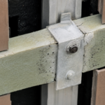
- Bolted connection geometry copied from steel details routinely violates minimum edge and end distance requirements specific to FRP laminates.
- A Minneapolis mid-rise project required full subgirt redesign and a six-week schedule hit after ignoring creep allowances and FRP connection geometry requirements.
Pultruded FRP Girts: A Rainscreen Risk Guide
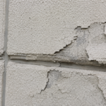
A Minneapolis mid-rise project discovered last spring that its pultruded FRP subgirt layout had deflected beyond tolerance at panel attachment points after a single winter of exposure, with no cladding yet installed. The specification team had lifted the subgirt layout directly from a steel detail: same span, same connection geometry, same fastener embedment depths.
No creep allowance. No modulus correction.
No bearing stress check at the connection holes. The result was a full subgirt redesign, a six-week schedule hit and a specification dispute that revealed how little consensus exists in commercial practice around FRP girt detailing.
That project is not an outlier.
Why FRP Subgirts Are Entering Commercial Specifications Now
ASHRAE 90.1-2022 Section 5. 5.
3. 1 tightened continuous insulation requirements for commercial assemblies in a way that makes metal subgirt attachment genuinely difficult to justify in IECC Climate Zones 4 through 8. The whole-wall U-factor calculation methodology in Appendix A applies isothermal plane correction factors that penalize metal-framed assemblies significantly and the penalty is proportional to the conductivity of the attachment element.
Steel subgirts running perpendicular to the insulation plane create linear thermal short-circuits that can reduce effective R-value by 30 to 50 percent relative to nominal, depending on framing percentage and profile geometry.
FRP’s thermal conductivity sits around 0.3 W/m·K. Steel runs roughly 50 W/m·K.
On paper, the substitution looks like a straightforward thermal improvement with no structural downside. That framing is the problem.
The market is accelerating faster than the available guidance: no AAMA standard and no ASTM standard currently governs FRP subgirt system design specifically for rainscreen applications. Designers are specifying these systems against a near-empty shelf of connection detailing resources.
What fills that void in practice is a mix of manufacturer span tables, structural engineering judgment borrowed from FRP bridge and industrial applications and, most commonly, steel subgirt details with the material designation changed. None of those sources adequately addresses the combination of sustained load, thermal cycling and tight panel tolerance that defines a commercial rainscreen environment.
The IECC 2021 compliance path through whole-wall U-factor calculations makes the thermal argument for FRP strong enough that specifications are moving forward regardless and the absence of a governing standard does not slow adoption. It just concentrates risk in the connection details and the serviceability criteria, which are exactly the places where FRP behaves least like the steel it is replacing.
Material Properties Facade Engineers Must Understand Before Specifying
Pultrusion produces highly anisotropic profiles. Longitudinal tensile strength for E-glass/polyester systems typically runs around 207 MPa, which looks competitive with structural steel on a per-area basis.
The problem is that facade connection loads are rarely aligned with the pultrusion axis. Transverse tensile strength and interlaminar shear strength are resin-dominated properties and they are substantially weaker, often by a factor of five to ten relative to longitudinal values.
When a cladding clip bears against the web of an FRP channel at an angle, the load path runs directly into the assembly’s weakest plane.
Modulus of elasticity for pultruded FRP profiles falls in the range of 17 to 21 GPa longitudinally. Steel runs approximately 200 GPa.
That order-of-magnitude difference means deflection governs FRP design far more often than strength does, a reversal of the typical steel design hierarchy that many facade engineers do not internalize until they run the numbers. A profile that passes a net section tension check by a comfortable margin may fail a serviceability check at the same span under the same load.
Engineers accustomed to steel subgirt design, where strength typically governs and deflection is a secondary check, need to reverse that priority when they move to FRP.
Resin system selection matters more in facade applications than in most structural uses. Vinylester resin systems outperform polyester in wet-wall conditions where moisture absorption affects resin-dominated properties over time.
In Climate Zones 5 through 8, where bulk water management at the rainscreen cavity is a design requirement and freeze-thaw cycling is a recurring condition, polyester resin systems can exhibit measurable property degradation over a ten-year service window. That degradation concentrates in transverse tensile and interlaminar shear values, which are already the weakest properties in the profile.
Specifying vinylester as a minimum resin system requirement in those climate zones is not conservative overreach; it is a direct response to the exposure condition the material will actually see.
ASTM D638 and ASTM D790 govern tensile and flexural property verification respectively; ASTM D2584 provides glass content verification. The ACMA Structural Design Manual publishes allowable stress tables for pultruded shapes and should be the baseline reference for any facade specification that touches FRP profiles.
Requiring manufacturers to submit third-party test data against these standards, rather than accepting catalog values alone, closes a meaningful gap between specified performance and delivered material.
The Deflection Problem: Why FRP Girts Behave Nothing Like Steel
The modulus gap between FRP and steel translates directly into span limitations that most facade specifications never reflect. An FRP channel profile of equivalent depth to a steel subgirt will deflect roughly ten times as much under the same load at the same span.
The L/240 serviceability limit commonly carried over from metal subgirt details becomes unachievable at standard girt spacings without significant span reduction, typically 30 to 40 percent shorter spans for equivalent load conditions. In practice, that span reduction means more attachment points back to the primary structure, more thermal penetrations through the insulation plane and a more complex bracket layout.
The thermal benefit of switching to FRP does not disappear, but it is partially offset by the increased frequency of structural connections required to keep the subgirt within deflection limits.
This matters because cladding panel systems have real joint tolerance limits. ACM panel systems and fiber cement panels typically allow plus or minus 3mm of movement at attachment points before joint alignment degrades visibly and sealant at panel perimeters begins to work.
Wind pressure loading at a 10-story facade in a 90 mph design wind speed zone can produce deflections well above that threshold in an FRP subgirt running at the same span a steel subgirt would handle without concern. IBC 2021 Section 1604.3 establishes serviceability criteria for cladding support members, but the code does not tell you what modulus your subgirt material has.
That calculation is the engineer’s responsibility. A 6-inch FRP pultruded channel at a 48-inch span under 25 psf wind pressure will produce a midspan deflection that exceeds the 3mm panel tolerance before the calculation reaches the strength check.
Running that number is a five-minute exercise. Not running it is how projects end up with visible joint misalignment at the first post-installation wind event.
Dynamic response under gusting wind loads adds another layer. FRP’s lower mass and stiffness combination can produce resonance behavior not seen in steel subgirt assemblies on tall facades.
This is not a theoretical concern; it is a documented phenomenon on high-rise curtainwall and rainscreen projects where lightweight attachment systems interact with facade aerodynamics. Facades above eight stories in high-wind zones should include a dynamic response check for FRP subgirt assemblies, particularly where girt spans approach the upper end of the manufacturer’s published table.
Downstream consequences include AAMA 501.1 dynamic water penetration failures driven by joint movement rather than water volume. Manufacturer span tables, where they exist at all, are built on uniform distributed load assumptions that do not account for eccentric point loads at discrete cladding clips.
A clip bearing on the bottom flange of an FRP channel introduces torsion that a uniform load table does not capture and torsional stiffness in pultruded open sections is low enough that this load case warrants an independent check.
Creep Under Sustained Load: The Failure Mode Specifications Ignore
Steel does not creep at ambient temperatures. FRP does.
This is the most consequential material behavior difference in facade applications and it is the one most completely absent from commercial facade specifications that adopt FRP as a subgirt material.
Creep in pultruded FRP is time-dependent deformation under sustained stress and it occurs at stress levels well below ultimate strength. Dead load from cladding panels, continuous insulation, clips and subgirt self-weight constitutes exactly the sustained loading condition that drives creep.
That deformation accumulates over years and is not recoverable. A subgirt assembly that meets installation tolerances on day one may exceed them by year three or year five as creep deflection compounds.
The Minneapolis project documented visible deflection after a single winter with no cladding installed, meaning the sustained load was only subgirt self-weight and clip hardware. Full cladding dead load would have accelerated that timeline significantly.
The ACMA Pre-Standard for LRFD of Pultruded Fiber-Reinforced Polymer Structures addresses this directly. It recommends limiting sustained stress to 25 percent of short-term allowable values to control creep within acceptable bounds.
That criterion dramatically affects profile sizing. A profile that passes a short-term strength check may require doubling in section depth or reducing span by half when the sustained load reduction factor is properly applied.
Facade specifications that reference FRP as a material substitution without engaging this criterion are not just incomplete; they are setting up a progressive failure. A 4-inch FRP channel that satisfies a peak wind load bending check at a 48-inch span will exceed the 25 percent sustained stress threshold under 4 psf dead load from fiber cement cladding at that same span.
The profile needs to be a 6-inch section or the span needs to drop to 36 inches or both. That is not a marginal adjustment; it changes the bracket layout and the insulation detailing across the entire facade.
Thermal cycling compounds the creep problem in rainscreen assemblies. Differential expansion between FRP girts and metal cladding clips causes micro-movement at connection points through every temperature cycle.
Over time, that movement elongates fastener holes and wears bearing surfaces. In a Minneapolis climate with 150 or more freeze-thaw cycles per year, a bolted FRP connection that starts at the correct geometry can develop measurable hole elongation within three to five years if bearing stress limits were not checked at design.
ASTM D2990 governs creep and creep-rupture testing for plastics and should be the basis for any long-term performance verification of FRP profiles in sustained load applications. Requiring manufacturers to submit ASTM D2990 creep data at the design stress level, not just at elevated stress levels used for accelerated testing, gives the specifying engineer actual data for the service condition rather than an extrapolation from a different load regime.
Connection Geometry Failures: Where Most Details Break Down
The connection is where FRP facade details fail most consistently and most predictably. Steel subgirt connection geometry relies on bearing stress capacity, bolt shear capacity and net section tension, all of which are well-characterized in steel design.
FRP connection design involves the same failure modes plus several that steel designers rarely encounter: net tension through anisotropic laminates, bearing stress perpendicular to the pultrusion axis, shear-out failure at bolt groups and delamination at loaded hole edges.
Edge distance and end distance requirements for bolted FRP connections are substantially larger than steel equivalents. A minimum edge distance of three times the bolt diameter and an end distance of five times the bolt diameter are common recommendations in FRP design guidance.
Steel details routinely use tighter geometry. When a facade team copies a steel connection layout into an FRP subgirt without rechecking these parameters, the resulting detail is under-designed at the connection even if the profile itself is adequately sized for bending.
A 1/2-inch bolt in a steel subgirt might use a 3/4-inch edge distance without concern. That same bolt in an FRP channel requires a 1.5-inch edge distance minimum.
On a 2-inch flange width, the difference between those two dimensions determines whether the connection is functional or a shear-out failure waiting to occur under full cladding load.
Hole drilling quality also affects connection performance in ways that steel design does not require engineers to consider. Pultruded FRP is sensitive to drilling technique at connection holes.
Dull bits, excessive feed rates and inadequate backing material during drilling produce delaminated hole edges that reduce bearing capacity below published values. A specification that requires FRP profiles but says nothing about hole preparation standards is leaving a meaningful portion of connection capacity to field conditions.
Requiring diamond-tipped or carbide drill bits, specifying maximum feed rates and requiring inspection of hole edges before fastener installation are not excessive requirements; they are the difference between achieving design bearing capacity and working with a degraded connection from day one.
Thermal isolation at the connection point also creates a geometry conflict. The whole point of specifying FRP is to eliminate the thermal bridge at the subgirt.
But many connection details reintroduce metal at the bracket-to-structure interface and if the FRP girt is through-bolted with steel fasteners through oversized holes, the fastener itself becomes a point thermal bridge. Stainless or coated steel fasteners reduce corrosion risk but do not eliminate conductivity.
Fiber-reinforced polymer fasteners exist and should be evaluated for low-load applications. High-load connections at heavy cladding panels require careful analysis before substituting non-metallic fasteners.
A 3/8-inch stainless steel bolt through an FRP subgirt at 16-inch spacing contributes a measurable point conductance that, when summed across a facade elevation, can reduce the effective R-value improvement from the FRP subgirt by 8 to 12 percent relative to the theoretical all-FRP assembly. That is not enough to negate the thermal argument for FRP, but it is enough to affect compliance calculations in Climate Zone 7 and 8 assemblies where the margin between compliant and non-compliant whole-wall U-factors is narrow.
Specification Language That Actually Reflects FRP Behavior
Most FRP subgirt failures begin in the specification, not in the field. The field installs what the documents describe.
When the documents describe an FRP profile by substituting it into a steel subgirt section without modifying performance criteria, the field has no path to a correct outcome.
A specification for pultruded FRP subgirts in a commercial rainscreen assembly needs to address at minimum: allowable deflection limits specific to the cladding system being attached, sustained load reduction factors applied to all dead load combinations, minimum edge and end distances at all bolted connections, bearing stress limits at cladding clip attachment points, resin system requirements based on climate zone moisture exposure and a requirement for independent engineering calculations rather than manufacturer span table compliance.
Referencing the ACMA Structural Design Manual as a governing document rather than a reference document is a meaningful distinction. A governing document creates a compliance obligation; a reference document creates a suggestion.
Submittals reviewed against a governing standard require the submitting party to demonstrate compliance with specific criteria. Submittals reviewed against a reference document can acknowledge the reference and move on.
For FRP subgirts, the difference between those two positions determines whether creep calculations, bearing stress checks and sustained load reductions actually appear in the submittal package or get deferred to a field condition that no one checks.
Requiring submittals to include creep-adjusted deflection calculations under sustained dead load, not just peak wind load deflection, closes the most common gap. The calculation format matters as well.
A submittal that shows midspan deflection under 25 psf wind pressure but omits the five-year creep deflection projection under 4 psf dead load is not a complete structural submittal for an FRP subgirt system. Specifying that submittals must include both calculations, with the creep projection based on ASTM D2990 data at the actual design stress level, forces the engineering to happen before installation rather than after the first inspection reveals out-of-tolerance conditions.
In IECC Climate Zones 6 and above, where the thermal performance argument for FRP is strongest, the sustained load environment is also most demanding due to temperature differentials and freeze-thaw cycling at connection points. That combination of thermal benefit and structural demand is exactly why the specification language needs to be more specific, not less.
What the Minneapolis Project Should Have Done Differently
The Minneapolis failure was a specification failure that became a field failure. The profile was adequate in bending under short-term wind load.
It was not adequate under sustained dead load when creep deflection was considered. The connection geometry was copied from a steel detail with edge distances that would have triggered shear-out failures under full cladding load.
The fastener embedment into the backup structure was sized for steel subgirt reaction forces without accounting for the different load distribution that a lower-modulus girt produces.
A lower-modulus girt distributes load differently to its end connections than a stiffer steel girt at the same span. The reaction force profile shifts and the connection at the backup structure sees a different demand than the steel calculation predicted.
That difference was not large enough to cause a connection failure in Minneapolis, but it was large enough to contribute to the deflection pattern that triggered the redesign. Recognizing that load distribution changes when modulus changes is a basic structural principle that the original specification team did not apply because they were working from a steel template rather than an FRP-specific analysis.
The project’s recovery required a complete structural re-analysis of the subgirt system, new connection details with FRP-appropriate edge distances, profile upsizing to meet the 25 percent sustained stress limit and a revised attachment bracket design that maintained the thermal break while achieving required bearing capacity. Six weeks and a significant cost impact later, the assembly performed as intended.
The redesigned system used a 6-inch vinylester FRP channel at 36-inch spans with 1.5-inch minimum edge distances at all bolted connections, stainless fasteners with neoprene washers to limit bearing stress concentration and a submitted creep calculation demonstrating deflection compliance at five years under full dead load. That is the specification the project needed from the start.
FRP subgirts are a legitimate thermal performance tool. The thermal conductivity argument is real and the energy code pressure behind it is not going away.
But specifying FRP without engaging its material-specific failure modes is not a conservative approach to thermal performance. It is a deferred failure.
The next project that adopts an FRP subgirt detail owes its owner a specification written for the material being installed, not the material being replaced.