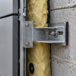
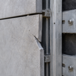
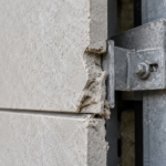
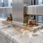
- A single underspecified base closure substitution caused a seven-figure remediation on a Climate Zone 6 mixed-use building.
- Zinc ribbon vents outperform mesh and brush seals at cavity bases by providing structurale rigidity and a capillary-breaking drainage profile.
- Increasing continuous insulation thicknesses under IECC 2021 are pushing cavity depths beyond the range of standard closure products.
- Drainage rate and ventilation rate are separate performance variables that respond differently to closure geometry and free-area percentage.
- Requiring photographic documentation of installed base closures before cladding proceeds prevents the most common field deficiencies at no meaningful cost.
Base Vent Selection Makes or Breaks Rainscreen Performance
Why the Base Closure Is the Cavity’s Most Critical Transition Point
A four-story mixed-use building in Climate Zone 6, completed in late 2021, began showing efflorescence and staining at the base course of its fiber cement rainscreen panels in year three. When the facade consultant arrived, the cavity inspection told the whole story in under an hour.
The installer had substituted a closed-cell foam backer rod closure for the specified open-mesh insect screen, reasoning that the drawings were “unclear. ” The WRB behind the continuous mineral wool had been saturated for an indeterminate period.
The bottom track of the metal framing showed early-stage corrosion. The substitution had been made on a single line item that carried no performance specification language whatsoever.
That line item cost the owner a seven-figure remediation.
The base of a rainscreen cavity is where three competing functions converge simultaneously: drainage outlet, ventilation inlet and pest exclusion. Most details treat it as only one of the three.
Pressure-equalized rainscreen theory depends on the cavity being open at top and bottom to allow pressure equalization across the cladding layer; a poorly chosen base closure can effectively convert a PE rainscreen into a face-sealed system. The base closure is also the lowest point where bulk water that has penetrated the cladding layer exits.
If the closure restricts drainage, water ponds against the WRB.
ASTM E2273, which establishes a test method for drainage efficiency in EIFS assemblies, is not directly applicable to open rainscreen cavities, but it establishes a principle that specifiers should carry forward: drainage rate is a measurable, specifiable performance attribute. We can define it.
We should require it. The fact that most specifications don’t is the core problem.
What makes the base condition uniquely demanding is the concentration of risk. Every other transition in a rainscreen assembly, the head, jamb, sill and top termination, manages one or two failure modes at a time.
The base manages all of them simultaneously while also sitting at the lowest point of the assembly where gravity works against you. Water that infiltrates anywhere above the base eventually arrives there.
Debris that enters the cavity from any source settles there. Insects that find any gap in the closure establish there.
The base closure is the last line of defense against all three and it has to perform that function continuously for the service life of the building without maintenance access. A specifier who treats it as a trim item is accepting a risk that the owner has not been told about and has not priced into the project contingency.
The Climate Zone 6 failure described above is not an outlier. Facade consultants working in cold and mixed-humid climates encounter variations of this failure pattern regularly.
The specific substitution varies, foam backer rod, spray foam, a strip of housewrap folded into the gap, a piece of rigid insulation cut to fill the cavity, but the mechanism is consistent. The installer encountered an underspecified condition, made a field decision that prioritized air sealing over drainage and ventilation and created a trapped moisture condition that the WRB was not designed to manage alone.
The WRB is a water-resistive barrier, not a waterproofing membrane. It tolerates incidental wetting.
It does not tolerate sustained saturation from ponded water with no drainage path.
The Three Closure Types and What They Actually Do
Not all base closures are interchangeable. The geometry problem at the cavity base demands that you understand what each product type actually does to airflow, drainage and structural continuity before you put it on a drawing.
Open-mesh insect screen, in fiberglass or aluminum, delivers the highest free-area percentage of the three types, typically 50 to 70 percent open depending on weave density. Drainage is excellent and ventilation is unimpeded.
The limitation is structural: mesh provides no support to the cavity gap itself and can compress under cladding load if it isn’t properly backed. Mesh aperture size matters significantly.
Most manufacturer guidance targets 1.5mm as the standard aperture for insect exclusion and anything coarser than that starts admitting mud daubers and small debris.
Fiberglass mesh is the more common specification in residential and light commercial work because it is inexpensive and widely available through cladding distributors. The practical problem with fiberglass mesh in commercial applications is long-term dimensional stability.
Fiberglass mesh in a cavity base that experiences repeated thermal cycling and UV exposure at the exposed face can degrade at the edges over a 10 to 15 year horizon, particularly in Climate Zones 1 through 3 where UV intensity is high. Aluminum mesh holds its geometry better under those conditions and is the appropriate choice for commercial applications where a 30-plus year service life is expected.
Neither mesh type provides meaningful structural support to the cavity gap, which means the furring system must be detailed to maintain the gap dimension independently of the closure product.
Zinc ribbon vent, in corrugated or sinusoidal profile, is rigid and self-supporting. It maintains the cavity gap dimension under load, which is a property mesh cannot offer.
Free area runs 30 to 50 percent depending on profile geometry, which is lower than mesh but still sufficient for pressure equalization in most assemblies. The corrugation profile acts as a capillary break and directs water outward rather than allowing it to wick back against the WRB.
Zinc is appropriate for contact with treated lumber and most cladding substrates. Aluminum ribbon vents are a viable alternative, but check galvanic compatibility with steel framing before specifying.
The corrugation geometry of zinc ribbon vent also provides a secondary benefit that is underappreciated in most specifications: it creates a defined drainage channel at the base of the cavity that directs water toward the exterior face of the vent rather than allowing it to pool horizontally against the WRB. In a flat mesh installation, water draining down the face of the WRB reaches the base and has no geometric feature directing it outward.
Surface tension can hold a thin film of water against the WRB face even when the mesh is fully open. The corrugated profile breaks that surface tension and provides a positive outward pitch to the drainage path.
In wind-driven rain conditions where water volume at the base can be significant, that geometric difference in drainage behavior is measurable.
Brush-seal and pile-seal closures belong at window and door perimeters. Full stop.
Their bristle density dramatically reduces free area, traps debris against the WRB and retains moisture in the one location where you most need drainage to be unobstructed. They are frequently misapplied when specifiers conflate “cavity closure” with “air seal.
” These are not the same function. A cavity base is not an air barrier plane; it is a drainage and ventilation plane.
The misapplication of brush seals at cavity bases tends to originate in specifications that were written for curtain wall or window wall assemblies and then adapted for rainscreen use without adjusting the closure type. Brush seals perform well at operable window perimeters where the primary requirement is air infiltration control and the drainage function is handled by a separate sill flashing.
Importing that product into a rainscreen base condition without understanding the functional difference produces a closure that excels at the one thing the cavity base does not need and fails at the two things it does.
If you want a decision framework, compare the three types across free area percentage, drainage capacity, structural rigidity and pest exclusion. Mesh wins on free area and drainage.
Zinc ribbon wins on structural rigidity and capillary break performance. Brush seal wins on pest exclusion and loses on everything else that matters at a cavity base.
Published free-area data from product manufacturers, including those producing drainage mat and vent products for rainscreen applications, is your primary reference for these numbers. Note that most published values are not independently tested; they are calculated from geometry.
ASHRAE 90.1-2022 does not specify vent type, but the continuous insulation requirements in Section 5. 8 that drive cavity depth indirectly affect the hydraulic head of water accumulating at the base.
Deeper cavities over thicker CI mean more water volume to drain in a wind-driven rain event.
How Energy Codes Are Breaking Old Details
IECC 2021 Table C402.1.3 and Table R402. 1.
2 have pushed continuous insulation thicknesses for Climate Zones 5 and 6 to levels that were uncommon in practice five years ago. A wood-frame assembly in CZ6 targeting code-minimum effective R-value now routinely carries 3 to 4 inches of continuous mineral wool or polyisocyanurate outboard of the sheathing.
That CI thickness drives furring depths that push rainscreen cavity dimensions from the traditional 3/8 to 3/4 inch range into 1 to 2 inches in some assemblies.
A 3/4-inch cavity and a 1.5-inch cavity have fundamentally different airflow and drainage dynamics. The base closure detail that was adequate for the shallower cavity is geometrically mismatched to the deeper one.
A standard 3/4-inch ribbon vent installed in a 1.5-inch cavity gap leaves 3/4 inch of uncontrolled open space above the vent. That gap admits birds and small rodents, accumulates debris and creates a dead-air zone at the base that undermines pressure equalization.
The product market has not fully caught up to this shift. Most ribbon vent products available through standard distribution channels are sized for 3/4-inch and 1-inch cavity depths.
Products sized for 1.5-inch and 2-inch cavities exist but require sourcing from specialty distributors and lead times can affect project schedules in ways that create pressure to substitute. That substitution pressure is exactly the condition that produces the field failures described in this article.
Specifiers who are designing assemblies with CI thicknesses that push cavity depths beyond 1 inch need to verify product availability and lead time before the project goes to bid, not after the framing is up and the cladding contractor is asking for a product submittal.
Specifiers are reusing master specification sections and standard details written for pre-energy-code-escalation cavity depths. The detail has not kept pace with the assembly.
This is not a criticism of the specifier; it is a systems problem in how master specs get updated. But it is producing failures.
The furring member geometry compounds this. Hat channel, wood strapping and Z-girts all create different seating conditions for the base closure.
A ribbon vent designed to seat against continuous wood strapping will not install continuously against hat channel without gaps at the fastener locations. Those gaps are where the insects enter and where the drainage restriction begins.
Hat channel in particular creates a recurring problem because the channel flanges sit proud of the CI surface at regular intervals and a ribbon vent that is cut to fit between hat channel legs rather than running continuously across them produces a base condition with periodic unprotected openings. The detail needs to show how the closure transitions across the hat channel leg, not just how it performs in the field of the wall between legs.
That transition condition is where most pest intrusion events originate in hat-channel-furred assemblies.
Z-girt assemblies present a different problem. The Z-girt leg that projects outward past the CI surface creates a thermal bridge that energy modelers account for, but it also creates a physical obstruction at the base closure location that most standard details do not address.
A ribbon vent running continuously across a Z-girt base condition needs to be notched or detailed around the girt leg and that notch is a potential gap in pest exclusion. The detail needs to show a solution, not just the ideal condition between girts.
Drainage Rate vs. Ventilation Rate: They Are Not the Same Variable
Specifiers frequently treat cavity base performance as a single variable. It is two.
Drainage rate and ventilation rate respond differently to closure geometry and optimizing for one can compromise the other.
Drainage rate at the cavity base is primarily a function of free area and the angle at which the vent profile directs water outward. A corrugated zinc ribbon vent with 40 percent free area and a profile that pitches water toward the exterior will outperform a flat mesh with 60 percent free area that allows water to drain vertically against the back face of the cladding.
The capillary break geometry matters as much as the open percentage.
Ventilation rate is a function of free area, cavity depth and the pressure differential between cavity interior and exterior. Pressure equalization theory requires that the cavity pressure track exterior pressure closely enough to prevent bulk water infiltration at cladding joints.
A closure that reduces free area below approximately 25 percent at the base begins to impede this equalization in deep cavities during high-wind events. This is not a code-defined threshold; it is a performance inference drawn from pressure equalization research and field observation.
The tension between these two variables becomes most apparent in tall buildings where stack effect creates a persistent upward airflow in the cavity. In a 10-story rainscreen assembly, the pressure differential between the base and the top of the cavity during winter heating season can be significant enough that the base closure is functioning as a ventilation inlet against a meaningful pressure gradient.
A closure with marginal free area that performs adequately on a two-story residential building may restrict airflow enough on a tall commercial building to create a negative pressure zone at the base that draws moisture-laden air into the cavity rather than expelling it. Building height is a system variable that should inform closure selection and it rarely appears in standard specification language.
The drainage and ventilation functions also have different peak demand timing. Drainage demand peaks during and immediately after a rain event.
Ventilation demand for drying is highest in the hours and days after a rain event when the cavity and WRB surface need to dry. A closure that performs adequately during the rain event but restricts the post-rain drying airflow is failing at the function that matters most for long-term assembly durability.
Drying rate is harder to measure than drainage rate, but it is the performance attribute that determines whether incidental wetting events accumulate into a chronic moisture problem over time.
The practical implication: in cavities deeper than one inch, specify a base closure with minimum 40 percent free area and confirm that the profile geometry directs drainage outward. For cavities at standard 3/4-inch depth with conventional furring, a standard zinc ribbon vent or open mesh at 50-plus percent free area is appropriate.
Do not let the product rep tell you that any listed closure is appropriate for any cavity depth. Cavity depth is a system variable and the closure must match it.
The Specification Gap That Creates the Substitution Problem
The failure case at the opening of this article was not primarily an installer error. It was a specification failure.
The installer substituted because the specification gave him the latitude to do so.
A performance specification for a rainscreen cavity base closure should define minimum free area as a percentage, maximum aperture size for pest exclusion in millimeters, minimum structural rigidity expressed as resistance to compression under a defined cladding load, material compatibility with the adjacent WRB membrane and any treated wood components and continuity requirements at furring member intersections. None of these requirements are exotic.
All of them are definable. Almost none of them appear in standard specification sections for rainscreen assemblies.
CSI MasterFormat Section 07 46 00 covers siding and cladding. Section 07 25 00 covers weather barriers.
The base closure detail falls in the gap between them and frequently gets assigned to whichever section the project architect finds most convenient. That gap is where performance language disappears.
The closure ends up described as “insect screen at cavity base, see detail,” and the detail shows a generic line with no material call-out.
The consequences of that gap extend beyond the substitution risk. When a base closure is not assigned to a specific specification section with defined performance requirements, it also has no defined submittal requirement.
No submittal means no product data sheet review before installation. No product data sheet review means the design team has no documented basis for confirming that the installed product meets the design intent.
When the moisture failure arrives in year three, the project record contains no evidence of what was specified, what was submitted or what was installed. The owner’s remediation claim against the contractor is weakened and the contractor’s defense against the claim is strengthened, by the absence of specification language that would have created a clear performance standard.
Section 07 27 00, Air Barriers, is another section where base closure language sometimes lands, particularly on projects where the specifier is thinking about the cavity base as an air control layer transition. That framing is not wrong, the base closure does occur at a critical air barrier transition, but assigning the closure to the air barrier section without also addressing drainage and ventilation performance in that section produces a specification that gets the air sealing requirement right and ignores the drainage requirement entirely.
The result is a well-specified air barrier transition with an underspecified drainage condition, which is a different failure mode than the one described at the opening of this article but produces the same saturated WRB outcome.
Write the performance requirement into the specification. Assign it to a section.
Make the installer prove compliance before the cladding goes on. This is not additional work; it is the work that prevents a seven-figure remediation in year three.
Galvanic Compatibility and Material Selection at the Base
Zinc ribbon vent is the default recommendation for most rainscreen applications over continuous insulation and it earns that position. But zinc is not universally appropriate and specifiers who treat it as a one-size answer will eventually produce a corrosion failure.
Zinc is compatible with treated lumber, fiber cement, most WRB membranes and concrete masonry. It is not compatible with uncoated aluminum framing components in wet conditions; the galvanic potential between zinc and aluminum in the presence of water is sufficient to produce accelerated corrosion of the aluminum over a 10 to 20 year service horizon.
If your assembly uses aluminum hat channel or aluminum Z-girts as the primary furring, specify an aluminum ribbon vent or an appropriately coated product and document the galvanic compatibility review in the project record.
The galvanic series places zinc at a more anodic position than aluminum, which means zinc will preferentially corrode in a zinc-aluminum couple. In a dry assembly that experiences only occasional wetting, this corrosion rate may be slow enough to be inconsequential over a 20-year horizon.
In a Climate Zone 5 or 6 assembly where the base closure is regularly wetted by drainage from the cavity above, the corrosion rate accelerates. The base closure is the wettest location in the assembly by definition, which means galvanic incompatibility at the base closure produces corrosion failures faster than the same incompatibility would at a drier location in the assembly.
Do not extrapolate from dry-condition galvanic compatibility data to wet-condition performance. The numbers are not the same.
Aluminum ribbon vents are a legitimate alternative in these assemblies. The tradeoff is that aluminum does not provide the same capillary break geometry as corrugated zinc in most product configurations and the free-area percentages vary enough between manufacturers that you need to verify against the actual product data sheet rather than the category assumption.
The WRB membrane at the base termination also matters. Self-adhered membranes with rubberized asphalt adhesive can react with certain coatings on metal vents over time.
Fluid-applied membranes that extend to the base termination edge need a clean substrate for adhesion and a ribbon vent installed before the fluid-applied WRB can create a shadow zone where the membrane doesn’t fully adhere. Sequence matters.
Detail the installation sequence explicitly, not just the final condition.
Stainless steel mesh is a third material option that resolves the galvanic compatibility question in mixed-metal assemblies. Type 304 stainless is compatible with both aluminum and zinc-coated steel framing components and does not corrode in the wet base closure environment.
The cost premium over aluminum mesh is significant, typically three to five times the material cost per linear foot, which limits its use to high-specification commercial projects where long service life and minimal maintenance access make the premium justifiable. On a 30-story residential tower with an inaccessible base condition behind a concrete podium, the cost premium for stainless mesh is a reasonable investment.
On a three-story wood-frame multifamily building with accessible base conditions, aluminum mesh or zinc ribbon vent is the appropriate specification.
What the Field Inspection Actually Reveals
After investigating moisture failures in rainscreen assemblies across Climate Zones 4 through 7 for two decades, a consistent pattern emerges at the base closure location. The failure is almost never the vent product itself.
It is the installation condition around the vent product.
The three most common field deficiencies, in order of frequency: first, the vent is cut short at inside corners and outside corners, leaving unprotected gaps of 2 to 6 inches where the cladding return meets the base condition. Second, the vent is installed at the correct height at the field of the wall but drops below the WRB termination at the transition to a concrete foundation wall, creating a direct path for water to enter behind the WRB.
Third, the vent is installed correctly but the cladding installer subsequently drives fasteners through it at the base course, compressing the corrugation profile and reducing free area by 60 to 80 percent at the fastener locations.
The corner condition deserves additional attention because it is the most consistently underdetailed condition in standard drawing sets. An inside corner in a rainscreen assembly requires the base closure to make a continuous 90-degree turn while maintaining the cavity gap dimension and the pest exclusion function.
Most ribbon vent products are not manufactured with pre-formed corner pieces, which means the installer is expected to miter-cut and lap the vent at the corner. Without explicit instruction in the detail and the specification, installers cut the vent to the corner and leave a gap.
That gap is typically 2 to 4 inches wide, unprotected and located at the lowest point of the inside corner where water from two wall planes converges. It is the highest-risk location in the entire base closure system and it appears as a blank space on most standard details.
The foundation wall transition is the second most consistently underdetailed condition. When a wood-frame wall above grade transitions to a concrete or masonry foundation wall below, the WRB termination, the base closure and the cladding base all occur at the same horizontal band.
The WRB needs to terminate above the base closure. The base closure needs to direct water outward past the face of the foundation wall.
The cladding base needs to clear the closure by enough to allow drainage without creating a capillary path back into the assembly. When these three conditions are not explicitly coordinated in the detail, the installer resolves the conflict in the field and the field resolution is almost always wrong in at least one of the three respects.
None of these deficiencies are visible once the cladding is on. All of them are preventable with a pre-cladding inspection hold point written into the project specification and the construction documents.
Require photographic documentation of the installed base closure before cladding installation proceeds. This adds one inspection event to the project schedule.
It costs less than a single day of remediation labor.
The photographic documentation requirement also changes installer behavior before the inspection occurs. When installers know that the base closure will be photographed and reviewed before the cladding goes on, the cut-short corners and the dropped transitions at foundation walls get corrected during installation rather than after the fact.
The inspection hold point is not primarily a quality control mechanism; it is a behavioral incentive that shifts the cost of correction from remediation to installation. That shift is worth more than the inspection itself.
Closing Recommendation: Specify the Cavity, Not Just the Cladding
The rainscreen cavity is a designed system with four control layers, defined airflow requirements and specific drainage performance expectations. The base closure is not a trim accessory.
It is the component that determines whether the water control layer and air control layer at the cavity base function as designed or fail silently behind the cladding for three years before anyone notices.
As CI thicknesses continue to increase under IECC 2021 and future code cycles, cavity depths will follow. The base closure details in your master specifications need to be reviewed against actual current cavity dimensions, not the dimensions that were standard when the master spec was last updated.
Pull the detail. Check the cavity depth against the CI thickness your current energy model requires.
Confirm the specified closure matches that geometry. If it doesn’t, fix it before the next project goes to bid.
The review process should include a check of the furring system geometry against the closure product geometry, a confirmation that the specified closure product is available from at least two distributors in your region, a galvanic compatibility review against the framing and cladding materials in the assembly and a sequence check to confirm that the installation order shown in the detail is consistent with how the work will actually be sequenced in the field. None of these checks require additional consultants or extended design time.
They require the specifier to look at the detail as an installation sequence rather than a final condition. Most standard details show the final condition.
The installer has to figure out the sequence. When the sequence is ambiguous, the installer makes a decision and that decision is where the failures originate.
The installer on that Climate Zone 6 building was not wrong that the drawings were unclear. He was wrong to substitute without an RFI.
But the specifier who left that line item without performance language created the condition that made the substitution possible. Own that gap.
Close it.