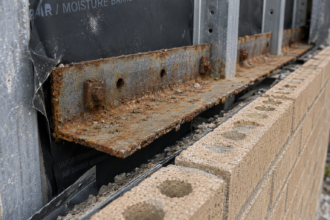




- Transition joints between dissimilar cladding systems fail because differential thermal and moisture movement is never calculated before sealant selection.
- Aluminum and terracotta can produce over 0.11 inches of differential movement across a 10-foot run, easily overwhelming an undersized joint.
- Sealant adhesion is substrate-specific and a primer optimized for aluminum can fail entirely on terracotta or fiber cement.
- Silicone, polyurethane and hybrid sealants each carry tradeoffs at mixed-material interfaces that require an explicit chemistry decision in the specification.
- Requiring a transition joint schedule as a named design deliverable is the single procedural fix that prevents this failure from repeating.
Why the Joint Between Two Cladding Systems Fails When Neither System Fails Alone
A forensic investigation on a five-year-old mixed-material commercial facade tells the story more efficiently than any design guide. Aluminum composite panels transition to fiber cement at the third-floor line.
Cohesive sealant failure runs along 80% of the transition joint length. Both cladding systems passed their individual water infiltration tests at substantial completion.
The joint was sized at 3/8 inch, specified with a standard silicone sealant and detailed identically to the field joints within each cladding zone. Nobody calculated differential movement at the interface.
Nobody owned that calculation.
That ownership gap is the root problem. Intra-system field joints are designed for known, uniform substrate movement within a single material type.
Inter-system transition joints, when they are designed at all, are sized by assumption, copied from adjacent field joint details or left to the contractor’s judgment in the field. No single specification section owns the transition joint.
Division 07 sealant specs reference movement capacity without calculating it. Division 08 and cladding sections stop at their own system boundaries.
ASTM C1193 Section 5.1 is explicit: joint movement capacity is a design input, not a post-selection check. The standard requires calculating anticipated movement before selecting sealant type or joint width.
That sequence gets inverted on most projects. The inversion is not accidental.
It reflects a procurement and coordination structure in which the sealant subcontractor is selected after the detail is drawn, the detail is drawn after the specification is written and the specification is written without a project-specific movement calculation to anchor it. Each step in that sequence inherits the error from the step before it.
The compounding effect makes transition joints uniquely dangerous. They accumulate movement differentials from two independent thermal mass systems simultaneously and forensic patterns consistently show that water intrusion at these locations is misattributed to flashing failure or substrate defects before sealant cohesive failure is identified as the primary mode.
That misattribution delays the correct repair, which means the wrong remediation gets installed and the same failure mechanism reactivates within two to three years. The investigation cost, the remediation cost and the repeat failure cost all trace back to the same uncalculated joint.
Calculating Differential Thermal Movement at Mixed-Material Interfaces: Where the Math Gets Ignored
The coefficient of thermal expansion values for common cladding materials are not secrets. Aluminum runs approximately 13 × 10⁻⁶/°F.
Fiber cement falls in the 4 to 5 × 10⁻⁶/°F range. Terracotta sits around 3.3 × 10⁻⁶/°F.
Stone ranges from 3 to 5 × 10⁻⁶/°F depending on type. GFRC lands near 5.5 × 10⁻⁶/°F.
These values are published in manufacturer data sheets and cross-referenced in AAMA 2410-15. They are not disputed. They are simply not used at transition joints with any regularity.
Work the math on a common scenario. A 10-foot panel run of aluminum transitioning to terracotta, with a 100°F service temperature range across IECC Climate Zone 5, produces a differential movement of approximately 0.115 inches.
That calculation: (13 × 10⁻⁶ minus 3.3 × 10⁻⁶) × 120 inches × 100°F = 0. 1164 inches.
A 3/8-inch joint specified with a Class 25 sealant per ASTM C920 has a total movement capacity of 0.1875 inches at ±25%. That sounds sufficient until you apply the safety factor AAMA 2410-15 recommends and add moisture-induced movement on the terracotta side.
Moisture-induced movement in fiber cement and terracotta adds a second, non-thermal movement vector that almost nobody includes in joint sizing at transitions. Fiber cement can exhibit hygroscopic movement in the range of 0.02 to 0.
04 inches per 10 feet across seasonal moisture cycling. That increment alone can consume the remaining capacity in an undersized joint.
Terracotta, depending on glaze coverage and installation exposure, can exhibit irreversible moisture expansion of 0.01 to 0. 03 inches per 10 feet in the first years after installation, a phenomenon sometimes called moisture expansion creep that is documented in the Brick Industry Association’s Technical Notes on Brick Construction and in manufacturer installation guides for architectural terracotta.
That expansion is permanent and additive to the thermal cycling range. A joint sized only for thermal differential on day one is already undersized before the first winter.
The standard joint sizing formula from AAMA 2410-15 is: joint width equals total movement divided by sealant movement capability, multiplied by a safety factor. The safety factor is routinely omitted at transitions.
When it is included, the required joint width frequently exceeds what the architectural detail accommodates aesthetically. That conflict gets resolved in favor of aesthetics.
The sealant fails. The pattern repeats across project types, climate zones and material combinations because the calculation is never made visible at the point in the design process when the aesthetic decision is being made.
If the architect sees a required joint width of 5/8 inch next to a field joint width of 3/8 inch on the same elevation, that is a conversation that happens during design. If nobody runs the number, the conversation never happens and the 3/8-inch joint gets installed everywhere.
Two Substrates, One Sealant, Zero Compatibility Testing: The Adhesion Assumption Problem
Sealant adhesion is substrate-specific. A silicone sealant with documented adhesion to anodized aluminum has no guaranteed adhesion to uncoated fiber cement, unsealed terracotta or cut stone edges without independent testing on the actual project substrate.
This is not a subtle point. ASTM C794 requires adhesion-in-peel testing on the actual project substrates, not on generic material categories.
Testing on “aluminum” does not cover anodized aluminum with a specific coating. Testing on “fiber cement” does not cover the factory-primed edge condition at a cut joint.
Primer selection at transition joints compounds the problem. A primer optimized for metallic substrates may be incompatible with the cementitious or ceramic substrate on the other side of the same joint.
Most sealant manufacturer technical data sheets address single-substrate primer recommendations. They rarely address simultaneous compatibility requirements across a dissimilar interface.
That gap pushes the decision to the field applicator, who resolves it by using whatever primer was specified for the dominant cladding system. On a project where aluminum composite panels represent 70% of the facade area and terracotta represents 30%, the applicator defaults to the aluminum primer system.
The terracotta side of every transition joint receives a primer that was never tested on that substrate. Adhesion failure on the ceramic side follows within two to four thermal cycles.
Surface energy differentials between metallic and cementitious substrates directly affect sealant wetting behavior and long-term adhesion durability. Aluminum presents a relatively high-energy surface that promotes sealant wetting.
Unsealed terracotta and fiber cement present variable, lower-energy surfaces that are also porous and moisture-active. The sealant behaves differently at each bite.
On the aluminum side, the sealant wets quickly and forms a consistent adhesion interface. On the terracotta side, the sealant may bridge surface porosity without fully wetting the substrate, creating a mechanically bonded rather than chemically bonded interface that performs adequately under static conditions and degrades under cyclic movement.
That degradation is not visible at substantial completion and does not appear in a standard water infiltration test. It shows up in year three or four as adhesion loss along the ceramic substrate face.
Field conditions introduce a third adhesion variable. Transition joints frequently land on substrate edges that are cut, ground or factory-finished differently than the field substrate face.
A fiber cement panel cut in the field presents a raw, unsealed edge with exposed aggregate and cement matrix. That cut edge absorbs primer and sealant differently than the factory-primed face.
ASTM C1521 provides the in-place verification protocol for confirming adhesion after installation. It is specified far less often than ASTM C794 and performed in the field even less often than it is specified.
Requiring ASTM C1521 pull testing at transition joints as a contract deliverable, with a minimum of one test location per 50 linear feet of transition joint, creates a verification record that either confirms the installation or identifies the adhesion problem before the facade is enclosed.
Silicone, Polyurethane or Hybrid: Why Sealant Chemistry Selection at Transition Joints Demands a Different Decision Tree
Silicone sealants offer superior UV and temperature resistance with high movement capability. Structural-grade silicones achieve Class 100/50 per ASTM C920, meaning they accommodate 100% extension and 50% compression relative to original joint width.
That performance envelope handles high-differential transition joints effectively on the movement side. The liabilities are real: silicone stains porous substrates, bonds poorly to cementitious materials without specific primers and is not paintable.
On a transition joint between aluminum panels and terracotta, silicone solves the movement problem while creating a staining and adhesion problem on the ceramic side. The staining liability is not cosmetic in the traditional sense.
Silicone oil migration into unglazed or partially glazed terracotta creates a permanent hydrophobic surface contamination that prevents future sealant adhesion if the joint requires remediation. The remediation cost on a stained terracotta transition joint is substantially higher than the original installation cost because the contaminated substrate must be mechanically prepared before any new sealant system will bond reliably.
Polyurethane sealants are paintable and often achieve better adhesion to cementitious substrates without primer in certain formulations. They typically fall into Class 25 or Class 35 per ASTM C920, which limits their movement capacity at high-differential joints.
UV degradation at exposed joints is a documented failure mode for polyurethanes and their temperature resistance ceiling is lower than silicone. At a south-facing transition joint in IECC Climate Zone 3, a polyurethane’s long-term durability is genuinely questionable.
Surface temperatures on dark-colored cladding in Climate Zone 3 can reach 160°F to 180°F on south and west exposures. Polyurethane sealants begin to soften and lose cohesive strength at sustained temperatures above 140°F in many standard formulations.
That softening allows the sealant to flow under gravity and compression loading, which changes the joint geometry and reduces effective movement capacity. The joint that was installed at the correct width and depth progressively loses its geometry over three to five years of thermal cycling at extreme surface temperatures.
Hybrid sealants based on silyl-terminated polyether or silyl-terminated polyurethane chemistry offer broader substrate compatibility and improved adhesion across dissimilar surfaces. The tradeoff is limited long-term field performance data at high-movement transition joints specifically.
The chemistry is sound; the 20-year track record at demanding interfaces is not yet established. Several manufacturers have introduced silyl-terminated polyether products with Class 50 movement ratings and documented adhesion to both metallic and cementitious substrates without substrate-specific priming.
Those products address the chemistry compromise problem directly. The specification writer who defaults to a standard two-part silicone because it is familiar is making a chemistry decision without evaluating whether that chemistry actually solves the adhesion problem on both sides of the joint.
The decision matrix trigger is this: when two substrates at a transition joint require chemically incompatible sealant types to achieve reliable adhesion on both sides, the joint forces a chemistry compromise. That compromise must be explicitly documented in the specification with the reasoning stated.
It cannot be resolved informally in the field by a subcontractor choosing between two tubes on a cart.
Joint Width, Depth and Backer Rod Placement: Why Transition Joint Geometry Cannot Be Copied from Field Joint Details
The 2:1 width-to-depth ratio for sealant joints is not a guideline. It is a functional requirement for achieving the hourglass deformation profile that allows sealant to accommodate movement without tearing at the adhesion interface.
Transition joints violate this ratio routinely when joint width is set by aesthetic alignment with adjacent field joints rather than by movement calculation. A joint sized at 3/8 inch for appearance, when the movement calculation requires 5/8 inch, will be installed at the wrong width regardless of what the specification says, because the installer is aligning to the adjacent field joint pattern.
The specification says 5/8 inch; the adjacent field joint is 3/8 inch; the installer splits the difference or matches the field joint. This is not installer negligence.
It is a predictable response to a detail that presents conflicting geometric information without explaining the reason for the discrepancy. When the drawing notes the required joint width and explicitly states that the transition joint width differs from adjacent field joints due to differential movement requirements, installers follow the note.
When the note is absent, they follow the pattern.
Three-sided adhesion is the most common geometric failure mode at transition joints. When the transition joint lands on a continuous substrate ledge, shelf angle or flashing return, the sealant bonds to the back surface as well as the two sides.
Three-sided adhesion prevents the sealant from deforming freely under movement and concentrates stress at one adhesion interface until it fails. Backer rod selection and placement directly prevents this condition.
Closed-cell backer rod sized at 25% larger than the joint width creates the bond-breaker surface that forces the correct two-sided adhesion geometry. Open-cell backer rod is inappropriate at transition joints between dissimilar cladding systems because it absorbs water and holds moisture against the substrate, which accelerates adhesion degradation on hygroscopic substrates like fiber cement and terracotta.
The specification must call out closed-cell backer rod explicitly. A generic backer rod reference allows the installer to substitute open-cell material, which is typically less expensive and more readily available.
The complication at transition joints is that the substrate geometry on each side of the interface is often different. One side may present a clean panel edge; the other may present a mortar joint face, a flashing leg or a sill condition with variable depth.
Installing backer rod consistently across that geometry requires coordination that field joint details do not address. A transition joint that runs from a clean aluminum panel edge on one side to a shelf angle flange on the other side presents two different depth conditions within the same joint run.
The backer rod diameter that produces the correct sealant depth at the panel edge may produce a three-sided adhesion condition at the shelf angle. That conflict must be resolved in the detail, with a section cut showing the backer rod position at each substrate condition.
This is a detailing problem that must be resolved at the drawing set level, not in the field.
The Specification Gap That Keeps This Failure Mode Alive
The technical solutions for transition joint failures are available. The calculation methods exist.
The test standards are published. The sealant chemistries are on the market.
The failure persists because the specification structure on most commercial projects does not require anyone to perform the transition joint analysis as a discrete design task.
Division 07 92 00 sealant specifications on standard CSI-format project manuals reference ASTM C920 Type S, Grade NS, Class 25 and move on. The movement capacity class is specified without a project-specific calculation confirming that Class 25 is sufficient at any particular joint location.
Transition joints between dissimilar cladding systems are not called out as a separate joint type requiring separate analysis. The envelope consultant’s scope, where one is engaged at all, typically ends at system-level performance verification rather than joint-by-joint movement accommodation review.
The ASTM C1193 guide specification, which is the most commonly referenced installation standard for sealant joints in commercial construction, includes a joint schedule format in its appendix that explicitly calls for listing joint location, substrate materials, movement calculation and sealant selection as linked entries. That appendix format is almost never reproduced in project specifications.
It exists in the standard; it does not appear in the project manual.
The gap between the standard’s intent and the project specification’s content is not a code enforcement problem. No building official reviews sealant joint schedules at permit.
No third-party inspector verifies that the specified sealant class matches a project-specific movement calculation. The quality control mechanism is entirely internal to the design team, which means it functions only when the design team has explicitly assigned responsibility for the calculation to a named party with a defined deliverable.
On most projects, that assignment does not exist. The sealant subcontractor submits a product data sheet showing ASTM C920 compliance, the submittal is reviewed for specification conformance rather than for movement adequacy and the joint gets installed without anyone having confirmed that the specified product can actually accommodate the movement at the specific transition location.
The practical correction is straightforward. Require a transition joint schedule as a project deliverable, formatted like a door schedule, listing each dissimilar material interface by location, the CTE values for both substrates, the calculated differential movement, the required joint width and the specified sealant class.
Make the calculation visible. When the required joint width conflicts with the architectural detail, that conflict surfaces during design rather than during a forensic investigation five years after substantial completion.
Attach the transition joint schedule to the Division 07 92 00 specification section as a required contractor submittal, with a note that the schedule must be reviewed and accepted by the envelope consultant before sealant installation begins at any transition location. That single procedural requirement creates the accountability structure that the standard specification format does not provide.
What the Next Project Requires Before the Drawings Are Issued
Every mixed-material facade with two or more cladding systems meeting within the same elevation or at a floor-line transition needs a transition joint movement analysis performed before the sealant specification is written. Not after.
Not as a submittal review comment. Before.
Pull the CTE values for both materials from published data. Establish the service temperature range for the project’s climate zone using IECC data.
Include moisture-induced movement for hygroscopic materials. Apply the AAMA 2410-15 safety factor.
If the resulting joint width conflicts with the architectural intent, that is a design decision that belongs to the architect and envelope consultant, made with full knowledge of the tradeoff. The alternative is leaving that decision to a sealant installer who is working from a field joint detail that was never designed for the interface in front of them.
Assign the transition joint analysis to a named party in the project’s design responsibility matrix. On projects with an envelope consultant, that assignment belongs to the envelope consultant with a defined deliverable date tied to the construction document phase.
On projects without an envelope consultant, the specification writer must own it, which means the specification writer must perform or commission the movement calculations before the sealant section is drafted. The sequence matters.
A sealant specification written before the movement calculations are complete is a specification written in the wrong order and the wrong order produces the wrong joint.
Require ASTM C794 adhesion testing on actual project substrate samples before the sealant product is confirmed. That testing takes two to three weeks and costs a fraction of a single day of facade remediation.
Require ASTM C1521 in-place verification at transition joints as a contract deliverable, with test locations identified on the drawing set rather than left to the contractor’s discretion. Document the primer selection for each substrate at each transition joint in the specification, not in a field memo after installation has started.
The transition joint is not a detail problem. It is a design problem that gets misclassified as a detail problem, which is precisely why it keeps failing.