- A 30mm granite panel value-engineered to 20mm loses 67% of its kerf bearing area while anchor hardware remains unchanged.
- Granite, limestone and marble fail differently at the kerf and each requires lot-specific ASTM C880 testing before fabrication begins.
- Thermal cycling creates cumulative microcracking at kerf corners that is invisible from the exterior until catastrophic panel failure occurs.
- IBC 2021 engineered design exemptions transfer liability to designers who often use non-conservative calculations for thin panel systems.
- A single specification sentence requiring facade engineer approval for any thickness reduction can prevent the most common kerf failure pathway.
Thin Stone Veneer: Kerf Depth and Anchor Risk
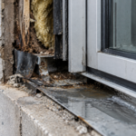
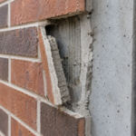
A granite panel on a nine-story commercial facade in the mid-Atlantic region spalled cleanly at the kerf slot during a January cold snap, dropping a 14-pound fragment onto a pedestrian canopy below. The post-incident investigation revealed the panel had been value-engineered from 30mm to 20mm thickness six months before fabrication.
The anchor bearing area at the kerf had been reduced by nearly one-third, yet the original anchor hardware and spacing remained unchanged. This single incident triggered a full facade audit, three insurance claims and a re-specification of 47 panels across two elevations.
How Kerf Anchor Systems Transfer Load: and Why Stone Thickness Is the Critical Variable
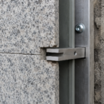
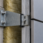
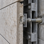
A kerf anchor system works by cutting a continuous or intermittent slot into the panel edge, then seating a metal clip or continuous extrusion into that slot to transfer loads back to the subframe. Simple in concept.
Unforgiving in execution when the stone cross-section shrinks.
Three distinct load paths converge at that slot simultaneously. Dead load bearing transfers the panel’s self-weight through gravity, bearing directly on the anchor clip seated in the kerf.
Out-of-plane wind pressure and suction pull and push the panel face, loading the kerf walls in bending. In-plane thermal racking imposes differential movement between panel and subframe, creating cyclic shear at the same narrow stone section.
No other point in the assembly concentrates this combination of stresses.
The geometry of a standard kerf slot runs 6 to 8mm wide and 15 to 20mm deep. On a 30mm panel, a 15mm kerf depth leaves a 15mm residual lip above and below the slot.
That lip is the sole structural element resisting anchor bearing stress. Reduce panel thickness to 20mm with the same kerf geometry and that lip shrinks to 5mm.
ASTM C1242, the standard guide for selection, design and installation of dimension stone attachment systems, addresses net section calculations at mechanical attachment points directly. The standard requires that designers evaluate the remaining stone area after kerf cutting against the combined applied stress.
Most value engineering exercises never revisit this calculation.
What makes this particularly consequential is that the residual lip is not a uniform structural element. Stone is anisotropic.
The rift plane orientation relative to the kerf cut determines whether the residual section is splitting parallel to a plane of weakness or across it. A 15mm lip cut perpendicular to the rift plane in a well-oriented granite behaves very differently from a 15mm lip cut parallel to a foliation plane in a marginal quarry lot.
Designers who treat the residual section as a homogeneous block of material with published average strength values are working with a non-conservative model. ASTM C1242 explicitly requires that the designer account for the anisotropic character of the stone when evaluating net section capacity, but this requirement is routinely treated as a formality rather than a calculation input.
The anchor clip geometry compounds the problem. Most standard kerf clips are designed with a nominal 2mm clearance between the clip bearing face and the kerf slot wall.
That clearance exists to accommodate thermal movement and installation tolerance. When bearing stress is applied, the clip contacts the slot wall over a contact length that is a fraction of the kerf depth.
Stress concentration at the contact point, not average bearing stress across the full lip area, governs failure initiation. A 5mm residual lip with a concentrated contact stress at its inner corner is not five-thirds as strong as a 3mm lip.
The stress concentration factor at a re-entrant corner in a brittle material makes the relationship nonlinear and consistently more dangerous than simplified bearing area calculations suggest.
When Panel Thickness Gets Cut: How Value Engineering Erodes the Kerf Safety Margin
The trajectory is predictable and I have seen it repeat on projects across every building type. The original specification calls for 30mm panels.
The GC flags stone as a line item for savings. The architect, under schedule pressure, accepts a reduction to 25mm.
A second round of value engineering pushes the spec to 20mm or 19mm minimum, which is often the thinnest the fabricator will quote without a custom setup charge.
At no point in this process does anyone recalculate anchor geometry. The anchor hardware was selected in design development, locked into the subcontractor’s bid package and treated as fixed.
The subcontractor has no contractual obligation to flag the incompatibility. The fabricator cuts the kerf to the depth shown on the approved shop drawings, regardless of how much residual section remains.
The math is straightforward. A 30mm panel with a 15mm-deep kerf retains 15mm of bearing lip.
A 20mm panel with the same kerf retains 5mm. That is a 67% reduction in bearing area carrying an identical anchor load.
The Indiana Limestone Institute Dimension Stone Design Manual publishes minimum recommended panel thickness tables relative to anchor type and panel area. The MIA+BSI Dimension Stone Design Manual VIII provides thickness-to-anchor ratio guidance that makes this relationship explicit.
Both references sit unused on most project bookshelves while the value engineering session proceeds.
The specification gap is structural, not procedural. Anchor hardware and panel thickness are treated as independent variables on most projects.
They are not. Every change to panel thickness must trigger a re-evaluation of kerf geometry, anchor spacing and bearing stress at the net section.
This is not a best practice recommendation. It is a structural necessity.
What the value engineering log never captures is the downstream cost of the decision. The $18,000 saved on material thickness gets recorded as a project win.
The anchor re-evaluation that should follow costs perhaps $4,000 in engineering time and might require a $12,000 anchor hardware change. Neither cost appears on the value engineering log because neither was requested.
The facade engineer of record is typically not in the room when the thickness reduction is accepted. By the time the shop drawing review cycle begins, the thickness is already locked into the fabricator’s cutting program and the anchor hardware is already on order.
Reversing the decision at that stage costs more than the original savings, so the incompatible combination gets built.
The shop drawing review process offers one more intervention point that is consistently underused. When a facade contractor submits kerf anchor shop drawings, the submittal package should include a net section calculation for the revised panel thickness.
Most submittal review checklists do not require this calculation. The reviewer checks anchor type, clip material, fastener size and subframe connection.
The residual stone section at the kerf goes unchecked because it was not on the original design drawing and the reviewer has no basis to flag its absence. Closing this gap requires the specification to explicitly require a net section calculation as part of the anchor system submittal, not as a separate engineering deliverable that arrives months later.
Stone Is Not Homogeneous: How Granite, Limestone and Marble Fail Differently at the Kerf
Specifying “stone veneer panels” without material-specific testing is an immediate red flag. Granite, limestone and marble behave differently under load and they fail differently at the kerf.
Granite carries a modulus of rupture typically in the 14 to 20 MPa range. Limestone runs 7 to 14 MPa.
Marble ranges 10 to 18 MPa with significant variability by source quarry. These are not interchangeable values and the lower end of each range represents real quarry lots that reach real job sites.
Marble presents a specific failure mode that compounds kerf risk. Thermal cycling causes irreversible bowing, commonly called dish warping or hysteretic deformation.
As the panel bows, the contact geometry between anchor clip and kerf wall shifts away from the design assumption. Bearing stress concentrates at kerf corners rather than distributing across the full contact length.
Corner stress concentrations initiate fracture in a material that has already been weakened by thermal fatigue.
Limestone’s failure mechanism is different. Moisture infiltration at the kerf slot, which is essentially an open channel in the panel edge, allows freeze-thaw cycling to progressively degrade the residual lip through microcracking.
The damage accumulates below the surface before any visible spalling appears at the panel face. By the time you can see the problem, the section is already compromised.
ASTM C880 governs flexural strength testing of dimension stone. The standard is clear that testing must be conducted on samples oriented to match the direction of stress at the kerf, perpendicular to the rift plane where applicable.
Testing on generic published values or on samples cut in the wrong orientation produces non-conservative results. Lot-to-lot variation in limestone and marble can exceed 30%.
Test the actual quarry lot.
The practical implication of lot-to-lot variation is that a project specification citing published flexural strength values from a trade association manual may be referencing data collected from a different quarry face, a different extraction depth or a different decade of production. Quarry geology is not static.
A limestone source that consistently produced material at 12 MPa modulus of rupture ten years ago may be producing material at 9 MPa today as the extraction front moves into a different stratigraphic layer. The only way to know what is arriving at the fabrication shop is to test it.
Require the fabricator to submit ASTM C880 test results from the actual lot before the kerf cutting program begins. If the test results fall below the design assumption, the anchor spacing and kerf geometry need to be recalculated before a single panel is cut.
Granite presents its own variability problem that is less commonly discussed. The published modulus of rupture range for granite is wide and the lower end of that range is associated with specific mineralogical compositions, particularly high feldspar content and coarse grain structures.
A visually attractive granite with large feldspar crystals and a pronounced grain pattern may test at the low end of the published range. The aesthetic that drove the material selection may be inversely correlated with the structural performance at the kerf.
Facade consultants who review stone submittals for color and veining without requiring lot-specific ASTM C880 data are approving a structural assumption they have not verified.
Thermal Cycling as a Progressive Failure Driver at the Kerf Anchor Interface
Thermal movement at a stone panel is not a one-time event. It is a cyclic load applied hundreds of times over the service life of the assembly and the kerf interface absorbs every cycle.
A 1,500mm granite panel spanning between anchors with a 60-degree Celsius seasonal delta-T generates approximately 1.1mm of differential movement. The kerf anchor must accommodate this movement without bearing against the slot walls.
When anchor clearance within the slot is insufficient, each thermal cycle imposes a small bearing load on the stone at the slot walls. The damage mechanism is ratcheting: microcracking initiates at kerf corners and propagates inward toward the panel face with each successive cycle.
No single cycle causes failure. The assembly fails after the cumulative damage exceeds the residual section’s capacity.
Specifiers who reduce panel thickness without increasing anchor slot clearance or reducing anchor spacing create a system where thermal movement consumes the entire tolerance budget. There is no margin remaining for wind load or construction tolerance.
The system is operating at its limit from day one.
The inspection challenge makes this worse. Thermally-induced kerf cracking is invisible from the exterior face.
Close-range inspection from a swing stage will not detect it. Infrared thermography during a meaningful temperature differential can identify delaminated sections, but only after the damage has progressed far enough to create a detectable air gap.
AAMA 501.5 provides the test method for thermal cycling of exterior walls at the system level. ASHRAE 90.1-2022 climate zone data establishes design delta-T values by project location.
Both should inform anchor clearance design at the kerf before the shop drawings are issued.
The delta-T calculation deserves more attention than it typically receives in the specification phase. ASHRAE climate zone data provides seasonal temperature ranges, but the relevant thermal load at the panel surface is not the ambient air temperature range.
It is the surface temperature range, which includes solar gain on dark or polished stone surfaces. A dark absolute black granite panel on a south-facing elevation in Climate Zone 4 can reach surface temperatures of 70 to 80 degrees Celsius on a clear summer day while the ambient air temperature is 35 degrees Celsius.
The same panel surface in January may reach minus 15 degrees Celsius during a radiative cooling event on a clear night. The effective delta-T driving thermal movement is not the 50-degree seasonal ambient range.
It is closer to 90 degrees and the differential movement calculation changes accordingly. A 1,500mm panel with a 90-degree Celsius effective delta-T generates approximately 1.6mm of movement, nearly 50% more than the calculation based on ambient temperature range alone.
Anchor slot clearance designed for the ambient range has no margin for the actual surface temperature range. This is a systematic non-conservatism that appears repeatedly in facade engineering calculations and is rarely caught during submittal review.
The cumulative nature of the damage also means that the failure risk profile of a kerf-anchored stone facade is not constant over time. A system that performs adequately in the first five years may be approaching its capacity limit by year fifteen as microcracking accumulates.
Facade maintenance programs that rely on visual inspection from grade or periodic swing stage surveys are not detecting this progressive degradation. The panel looks intact until the residual section fails in a single event, typically during a wind or thermal loading episode that would have been well within the design envelope of an undamaged panel.
Code Minimums, Standard Gaps and the Specification Decisions That Fall Between Them
IBC 2021 Section 1404.10 addresses anchored stone veneer and references minimum thickness requirements, but the code language establishes a floor, not a design target. The code permits 2-inch (51mm) minimum thickness for exterior anchored stone veneer in most applications, with exceptions for thin veneer adhered systems.
Kerf-anchored panel systems operating at 20mm are well below the code’s anchored veneer provisions, which means they are being justified under an engineered design exemption that places full responsibility on the designer of record.
That exemption requires a complete structural analysis of the attachment system. In practice, it often receives a cursory review by a facade consultant who was not involved in the value engineering session that drove the thickness reduction.
ASTM C1242 provides the most detailed guidance available for engineered attachment design, but it is a guide standard, not a mandatory requirement. Its net section calculation methodology is best practice.
It becomes mandatory only when the project specification invokes it by reference. Most specifications do not.
The MIA+BSI Dimension Stone Design Manual VIII and the ILI Dimension Stone Design Manual both provide prescriptive thickness-to-anchor guidance that is more conservative than what value engineering typically produces. Neither document has code authority.
Both represent the industry’s collective knowledge about where panels actually fail.
The gap between code minimum and field-proven best practice is where most kerf failures originate. Closing that gap requires the specifier to invoke ASTM C1242 explicitly, require lot-specific ASTM C880 testing and mandate that any panel thickness change after design development triggers a documented re-evaluation of anchor geometry and net section bearing stress.
The engineered design exemption pathway under IBC 1404.10 deserves specific attention because it is increasingly the default justification for thin panel systems and the quality of the engineering behind that exemption varies enormously. The exemption requires that the attachment system be designed by a registered design professional and that the design account for all applicable loads.
It does not specify the methodology, the safety factors or the testing basis. A facade engineer who designs a 20mm kerf-anchored system using published average flexural strength values, ambient temperature delta-T and simplified bearing area calculations is technically complying with the exemption while producing a non-conservative design.
The building official reviewing the permit application has no practical basis to evaluate the adequacy of the methodology. The exemption functions as a transfer of liability rather than a guarantee of safety.
Specifiers can close this gap without waiting for code revision. A specification section that invokes ASTM C1242 by name, requires net section calculations to be submitted with the anchor system shop drawings, mandates lot-specific ASTM C880 testing oriented perpendicular to the rift plane and requires the facade engineer of record to review and approve any panel thickness change after design development creates a contractual framework that the code does not provide.
These requirements add cost. They add approximately 2 to 4 weeks to the submittal review cycle and require the facade engineer to remain engaged through the fabrication phase rather than completing their work at the permit stage.
That cost is a fraction of the cost of a single post-installation audit triggered by a panel failure.
What Facade Audits Actually Find: Field Conditions vs. Design Assumptions
Post-installation facade audits on kerf-anchored stone systems consistently reveal the same deviations. Anchor clips installed with insufficient clearance to the kerf slot walls.
Kerf depths cut to the drawing dimension on panels whose actual thickness has drifted toward the minimum tolerance. Shim packs installed to correct subframe plumb errors that consume the thermal movement clearance designed into the anchor.
These are not random errors. They are predictable consequences of a system where tolerances stack in one direction.
Stone panel thickness carries a fabrication tolerance, typically plus or minus 1.5mm. The subframe carries an installation tolerance.
The anchor clip carries a positional tolerance. When all three tolerances stack unfavorably on a panel already specified at minimum thickness, the residual bearing section at the kerf can be 30 to 40 percent below the design assumption before the first wind load is applied.
Close-range inspection during installation is the only reliable intervention point. Requiring the facade contractor to document kerf depth and anchor clearance on a percentage of panels during installation, before the next course is set, catches these deviations while correction is still practical.
After the facade is complete, your options are a full audit from swing stage access or acceptance of unknown risk.
Audit findings from completed facades add another layer of concern that installation-phase inspection cannot address. Panels that passed installation inspection with acceptable kerf clearances may show measurable clearance reduction after two or three thermal cycles if the subframe connection detail did not provide adequate slip capacity.
Anchor clips that were correctly positioned at installation can migrate within the kerf slot if the clip-to-subframe connection allows rotation under repeated wind loading. These are not fabrication or installation errors.
They are design details that perform differently in service than they perform in the shop drawing review.
The documentation gap compounds the problem. Most facade contractors do not maintain panel-by-panel installation records that would allow an auditor to correlate a specific panel’s field condition with its fabrication records.
When an audit identifies a panel with a 4mm residual lip and a kerf depth that matches the drawing dimension, the auditor cannot determine whether the panel was fabricated at the minimum thickness tolerance or whether the kerf was cut deeper than specified. Both scenarios produce the same field measurement.
Resolving the ambiguity requires either core sampling, which damages the panel or acceptance of the worst-case assumption. Specifying panel-by-panel fabrication records, including measured thickness at the kerf location and measured kerf depth, as a required submittal before panels ship from the fabrication shop gives the auditor the data needed to make that determination without destructive investigation.
Sounding surveys, where an inspector taps the panel face with a hammer or electronic sounding device to detect hollow areas, remain a standard audit tool but carry significant limitations on kerf-anchored systems. A delaminated section behind the panel face produces a detectable change in acoustic response.
A fractured kerf lip that is still in contact with the anchor clip does not. The panel sounds solid.
The anchor is carrying load on a section that has lost most of its tensile capacity. The only reliable detection method for this condition is close-range visual inspection of the kerf slot from above or below the panel edge, which requires either removal of the panel above or access from a position that allows direct sight into the slot.
Neither is practical on a completed facade without significant access cost.
The Specification Fix: What Needs to Change Before the Next Value Engineering Session
The next time a stone panel thickness reduction appears on a value engineering log, treat it as a structural change order, not a material substitution. Require the facade engineer of record to reissue the anchor geometry calculations with the revised thickness before the change is accepted.
Invoke ASTM C1242 by name in the specification and require that net section calculations be resubmitted for any panel thickness revision after design development. Specify ASTM C880 testing on the actual quarry lot, oriented perpendicular to the rift plane, with results submitted before fabrication begins.
Set a hard floor. For kerf-anchored panels in IECC Climate Zones 4 through 7, where freeze-thaw cycling at the kerf is a real degradation mechanism, 30mm should be the minimum thickness for granite and marble.
Limestone warrants 38mm minimum given its lower modulus of rupture and moisture susceptibility. These numbers are not arbitrary; they reflect the residual section geometry needed to maintain adequate bearing area with standard kerf depths while preserving clearance for thermal movement.
The fragment that fell on that pedestrian canopy in January weighed 14 pounds and dropped nine stories. The value engineering session that made it possible saved approximately $18,000 on material costs.
The audit, the claims and the re-specification cost orders of magnitude more. Specify the thickness the anchor system actually requires.
The specification language itself needs to be written so that the thickness floor is not a recommendation that can be overridden by a value engineering log entry. A specification section that states “panel thickness shall not be reduced below the minimums established in this section without written approval from the facade engineer of record, accompanied by revised net section calculations demonstrating compliance with ASTM C1242” creates a contractual gate that a value engineering log entry cannot pass through without triggering the engineering review.
This is not a complicated specification requirement. It is a single sentence that closes the most common failure pathway in kerf-anchored stone facade design.
The anchor spacing requirement needs the same treatment. Anchor spacing is typically specified as a maximum dimension and fabricators and installers routinely treat that maximum as the standard.
A specification that requires anchor spacing to be recalculated as a function of panel thickness, panel area, design wind pressure and the net section capacity of the kerf at the specified thickness produces a spacing requirement that is tied to the actual structural condition of the assembly rather than a generic maximum that was appropriate for a thicker panel. This calculation is not complex.
It is the calculation that should have been done during design development and repeated every time a thickness change was accepted. Making it a specification requirement rather than a design assumption ensures it gets done.
Finally, require a pre-installation conference that includes the facade engineer of record, the facade contractor and the stone fabricator’s technical representative. The agenda should cover kerf geometry verification, anchor clearance requirements, tolerance stacking analysis and the documentation requirements for panel-by-panel fabrication records.
Most pre-installation conferences for stone facade systems cover sequencing, protection and warranty. They do not cover the structural interface between the panel and the anchor.
That conversation needs to happen before the first panel is set, not after the first panel falls.