- PVDF coatings perform as advertised on intact panel faces but fail predictably at field-cut edges, drilled fasteners and open joints.
- Warranty documents from every major PVDF supplier explicitly exclude field modifications, a fact specifiers must address before writing the specification.
- Southern and high-altitude climates accelerate failure timelines that standard AAMA 2605 accelerated weathering tests were never designed to predict.
- Concealed fastener systems, factory edge treatment and supplemental cyclic corrosion testing per ASTM G85 Annex A5 shift the risk profile meaningfully.
- Shop drawing review is the last point at which field-cut edge footage and fastener counts can drive a required design change before installation begins.
PVDF Coatings on Metal Panels: Where the System Fails
A facade consultant called to investigate premature coating failure on a 2008-vintage aluminum composite panel rainscreen in Phoenix discovers that chalking, delamination and corrosion undercutting are concentrated not across the panel face where PVDF performs as advertised, but in a repeating grid pattern that maps precisely to every field-cut edge, every drilled fastener hole and every panel joint where installers scribed the material to fit. The warranty is still active.
The coating is not.
What PVDF Coatings Actually Promise: and What the Warranty Excludes
Polyvinylidene fluoride finishes, marketed under the 70% PVDF threshold that qualifies for Kynar 500 or Hylar 5000 branding, represent the highest tier of organic coating performance available for architectural aluminum. The chemistry matters: fluorine-carbon bonds in PVDF are among the most stable in polymer science, which is why these coatings resist UV degradation, chalking and color shift over decades of service.
Lower-grade fluoropolymer blends marketed with similar language but below the 70% resin threshold do not perform comparably and specifiers who accept “fluoropolymer finish” language in submittals without confirming resin content are accepting a material substitution. The distinction is not academic.
A 50% PVDF blend may pass a cursory visual review and carry similar marketing language while delivering meaningfully shorter service life under high-UV exposure. Requiring the manufacturer’s certified test report confirming resin percentage by weight, not just brand name citation, is the minimum verification step that closes that gap.
Factory coil-coating or spray-applied finishing achieves what field application cannot: continuous dry film thickness in the 0.8 to 1. 2 mil range per AAMA 2605-23, controlled cure temperatures that drive adhesion and substrate pretreatment through chromate or non-chromate conversion coating that creates the chemical bond between aluminum and finish system.
Coil-coating lines operate at cure temperatures between 400 and 500 degrees Fahrenheit, producing a cross-linked film that no field-applied product can replicate at ambient temperature. The conversion coating step, typically a chromate or zirconium-based treatment per ASTM D1730 Type B or C, creates the reactive interface that anchors the primer to the aluminum oxide layer.
Remove that interface through field cutting or drilling and the entire adhesion mechanism is severed at the breach point.
AAMA 2605-23 governs high-performance organic coatings on aluminum and sets the bar for warranty compliance. Section 7 warranty provisions and Section 5 application requirements share a common assumption: the coating was applied under factory conditions.
Field cuts, field drilling, field touch-up paint and any post-fabrication modification to the coated surface are excluded from warranty coverage in every manufacturer document I have reviewed. That exclusion is not buried.
It appears in the first or second page of every warranty document from every major PVDF coating supplier. Specifiers who miss it are not reading the documents.
More specifically, they are not reading the documents before writing the specification, which is the only point at which the exclusion can be addressed through design and detailing requirements rather than post-failure dispute correspondence.
The Three Failure Zones Every Specifier Should Map Before Approving Shop Drawings
Field modification of PVDF-coated panels creates three distinct failure zones. Each one operates through a different mechanism.
All three are preventable at the specification and shop drawing review stage if specifiers know what to require.
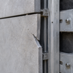
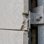
Cut edges are the most common and most damaging. Field sawing or shearing removes the coating entirely and exposes raw aluminum or steel substrate.
Touch-up coatings applied in the field cannot replicate factory pretreatment per ASTM D1730 and independent testing consistently shows field touch-up adhesion values running 30 to 50 percent below factory benchmarks. The substrate sits exposed at the cut face, protected only by whatever touch-up product the installer applied with a brush in ambient conditions.
In a rainscreen assembly with open joints, that edge faces continuous UV and moisture cycling with no backup protection. The geometry compounds the problem: a field-cut edge on a 4-millimeter aluminum composite panel exposes the core material, typically a polyethylene or fire-rated mineral core, in addition to the aluminum skin.
That core is hygroscopic in standard PE formulations and provides no corrosion resistance once the aluminum skin is breached. Forensic cross-sections from failed installations routinely show core delamination extending 10 to 20 millimeters back from the cut face, driven by moisture absorption that the face coating never had to manage because the face coating was never the problem.
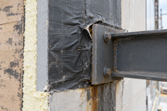
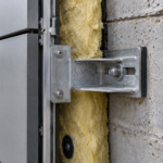
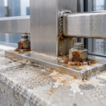
Fastener penetrations create a second failure mode that operates electrochemically. Drilling through a coated aluminum panel for exposed or semi-concealed fastener systems breaches the film at the penetration perimeter.
When a stainless steel fastener passes through an aluminum panel, galvanic potential between the two metals accelerates anodic dissolution of the aluminum at the breach. The galvanic series places stainless steel and aluminum approximately 0.25 to 0.
50 volts apart in seawater electrolyte, a potential difference sufficient to drive measurable corrosion current when moisture bridges the contact zone. ASTM B117 salt-spray data shows corrosion undercutting initiating at fastener penetrations within 500 to 1,000 hours of accelerated exposure.
That translates to observable field failure well within a 10-year warranty period in aggressive climates. Specifiers working in IECC Climate Zone 1 coastal environments should treat every field-drilled fastener penetration as a corrosion initiation site and detail accordingly, either by eliminating the penetration through concealed attachment or by specifying isolation washers and sealant collars at every penetration point.
Panel joints and reveals complete the failure map. Sealant-free open-joint rainscreen configurations expose cut panel edges continuously to UV, moisture and thermal cycling.
Joint geometry that allows water to pond or wick against those edges creates sustained wet contact that PVDF face coatings are not formulated to resist from the substrate side. The coating was designed to protect the face.
The edge is unprotected by design. Open-joint rainscreen assemblies are architecturally desirable and thermally rational, but they require that every exposed edge be treated as a primary weathering surface, not a secondary detail.
When the joint design places a cut panel edge in a horizontal or near-horizontal orientation, capillary action pulls water into the joint gap and holds it against the edge face through surface tension. That mechanism operates independently of rainfall intensity and continues during dew cycles and condensation events that no drainage-based detail can address.
Before approving any metal panel shop drawing package, specifiers should require panel layout drawings that quantify total linear footage of field-cut edges and total fastener count. Those two numbers tell you the actual risk profile of the installation.
How Southern and High-Altitude Climates Accelerate the Timeline
Geography compresses the failure timeline in ways that manufacturer warranty language does not acknowledge. Phoenix and Denver receive approximately 25 to 30 percent higher annual UV dose than mid-Atlantic baseline sites, based on NREL National Solar Radiation Database irradiance data and ASTM G173 reference spectra.
Miami adds high relative humidity and salt-laden marine air as compounding stressors on top of a UV load comparable to Phoenix. These are not marginal differences.
They represent meaningfully accelerated degradation rates for any coating system operating at a breach point. The NREL data for Phoenix shows annual global horizontal irradiance values averaging approximately 5.7 kilowatt-hours per square meter per day, compared to approximately 4.
5 for Baltimore and 4.7 for Atlanta. That difference accumulates over a 20-year service life into a total UV dose differential that no accelerated weathering test protocol currently accounts for when evaluating breach-point performance.
UV degradation of PVDF at cut edges and penetrations proceeds differently than degradation of intact film surfaces. The failure initiation point is the coating-to-substrate interface, not the coating surface.
Once moisture infiltrates a breach, it travels laterally between the coating and the conversion coating layer and chalking and delamination radiate outward from that point. The intact PVDF face coating may look acceptable for years while the substrate beneath is actively corroding from the edge inward.
This subsurface progression is why visual inspection at five to seven years post-installation frequently misses active failure. The coating surface retains gloss and color while the adhesion bond is failing across a widening front.
By the time blistering and delamination become visible, the affected zone extends well beyond what surface observation suggested and remediation scope expands accordingly.
Thermal cycling amplitude amplifies the mechanical stress at every breach point. Phoenix diurnal temperature swings of 30 to 40 degrees Fahrenheit drive differential expansion between aluminum substrate, which carries a coefficient of thermal expansion of approximately 13 times 10 to the negative sixth power per degree Fahrenheit and the coating film above it.
That differential fatigues the adhesion bond at pre-existing breach points with every thermal cycle across a service life measured in thousands of cycles. A panel installation in Phoenix accumulates roughly 7,000 to 8,000 significant thermal cycles over a 20-year service life, assuming one major swing per day.
Each cycle applies a peel stress at the breach perimeter. The cumulative effect is progressive delamination that accelerates as the delaminated zone grows, because a larger unbonded area transfers more stress to the remaining bonded perimeter with each subsequent cycle.
Forensic investigations at 15 to 20-year-old installations across Sun Belt markets are documenting failure patterns that AAMA 2605 accelerated weathering tests did not predict. The reason is straightforward: those tests used intact specimens.
Why Accelerated Weathering Tests Don’t Simulate the Field
AAMA 2605-23 qualification testing uses flat, unmodified coated panels. No cuts, no holes, no joints.
The protocol validates coating chemistry and factory application quality, which is exactly what it is designed to do. This is not a flaw in the standard.
It is an intentional scope limitation. The problem is that specifiers routinely read AAMA 2605 test compliance as whole-system durability assurance, which it is not and was never intended to be.
The standard’s own scope language restricts its applicability to the coating system as factory-applied. A coating that passes every AAMA 2605-23 requirement on an intact specimen can fail at field-modified locations within five years of installation without any contradiction between the test result and the field outcome.
Both data points are accurate. They are measuring different things.
Florida Exposure testing, conducted at 45 degrees south-facing in South Florida per ASTM D7869 or legacy ASTM G7, shares the same limitation. Ten-year Florida Exposure data cited in manufacturer literature documents intact specimen performance.
It tells you nothing about edge or penetration performance because the test specimens have no edges or penetrations that were created post-coating. The South Florida exposure site at Homestead, operated by multiple testing organizations, produces some of the most aggressive natural weathering data available for organic coatings and PVDF systems consistently perform well there on intact panels.
That performance record is real and defensible. It simply does not extend to the field-modified conditions that define most actual installations.
Cyclic corrosion testing per ASTM G85 Annex A5, the prohesion cycling protocol, is more predictive of edge and penetration failure than ASTM B117 salt spray alone because it combines wet and dry cycling phases that better simulate field exposure at breach points. The prohesion cycle alternates between a dilute salt-acid fog phase and a dry-off phase, producing a more realistic simulation of the wetting and drying cycles that drive undercutting corrosion at coating breaches.
AAMA 2605-23 does not require it. Specifiers can request it as a supplemental qualification requirement in the project specification and for projects in IECC Climate Zones 1 and 2 or high-altitude Zone 5 sites with aggressive UV, they should.
The test can be specified on scribed specimens, where a controlled cut through the coating to bare substrate is made before exposure, to generate data directly relevant to field-cut edge performance. That specimen geometry is not required by any current standard but is technically straightforward to specify and produces directly actionable data.
The gap in the current standard is specific: no AAMA or ASTM requirement mandates coating qualification testing on specimens that simulate field-modified conditions. Until that gap closes, the specification-to-field performance disconnect will continue generating forensic claims on installations that passed every required test.
What the Specification Can Actually Control
The warranty exclusion for field modification is not going away. Panel systems require field cutting.
Fasteners go through panels. The question is not how to eliminate field modification but how to specify systems that manage it with something better than brush-applied touch-up.
Several approaches shift the risk profile meaningfully. First, specifying concealed fastener systems with factory-punched or factory-routed attachment points eliminates field drilling of the coated face entirely.
The attachment geometry is engineered at the factory, the coating is applied over the finished panel and the fastener never penetrates the coated surface. This approach requires coordination between the panel fabricator and the structural attachment system and it costs more.
The premium for factory-punched concealed clip attachment over field-drilled exposed fastener systems typically runs 8 to 15 percent of panel system cost depending on panel size, layout complexity and clip spacing requirements. The tradeoff is real and worth naming explicitly in the specification narrative so that value-engineering conversations during design development are informed rather than reactive.
A specifier who can document that the cost premium buys elimination of 2,000 field-drilled penetrations has a defensible position when the owner’s cost consultant pushes back.
Second, requiring factory edge treatment on all panel perimeters, including edge seal coating or factory-applied edge cap extrusions, addresses the cut-edge exposure problem at the source. Some panel systems offer this as a standard detail.
Others require it as a specified option. Factory edge seal coatings, applied as a liquid sealant or as a co-extruded cap over the panel edge before shipment, provide a continuous barrier that brush-applied field touch-up cannot replicate in adhesion quality or film continuity.
Specifiers who do not ask for it will not get it and the submittal review stage is too late to introduce it if the fabricator has already cut and staged the panels.
Third, specifying minimum sealant joint width at panel-to-panel interfaces in open-joint rainscreen assemblies, combined with geometric controls on joint depth-to-width ratios, limits the sustained wet contact that drives edge corrosion. A minimum 3-to-1 depth-to-width ratio at horizontal joints, combined with a minimum 3/4-inch joint width, maintains drainage geometry that prevents capillary bridging across the joint gap.
This is a detailing requirement, not a coating requirement and it belongs in the section covering the rainscreen assembly, not the coating specification alone. Placing it only in the coating section creates a coordination gap where the installer follows the attachment detail without reference to the joint geometry requirement.
Reading the Shop Drawing Package as a Failure Map
Shop drawing review for metal panel systems is where specification intent either survives or collapses. Most shop drawing packages show panel layout, attachment details and joint profiles.
Few show the information that actually predicts coating durability: total field-cut edge footage, field drilling locations and touch-up product call-outs. The standard shop drawing submission format, as defined by most panel fabricators’ standard of care, is not organized around coating durability risk.
It is organized around fabrication and installation sequence. Those two organizational frameworks produce very different documents and the specifier who reviews a shop drawing package only for dimensional accuracy and attachment spacing is not reviewing it for the information that determines long-term coating performance.
Require it. The panel layout drawing should quantify every linear foot of field-cut edge and identify which edges receive factory edge treatment versus field touch-up.
That distinction should appear as a drawing note keyed to a legend, not as a general specification reference that the installer interprets in the field. The attachment detail should confirm whether fasteners penetrate the coated face or engage a concealed clip system.
Where exposed fasteners are unavoidable, the detail should show the isolation washer specification, the sealant collar geometry and the touch-up product application sequence. The submittal package should include the field touch-up product technical data sheet and that TDS should be evaluated against the factory coating system for compatibility and adhesion performance.
A touch-up product from a different manufacturer than the factory coating system introduces an unknown compatibility variable that no amount of field application care can resolve if the chemistry is incompatible.
When those documents reveal that a 10,000-square-foot panel installation includes 4,000 linear feet of field-cut edges treated with brush-applied touch-up and 2,000 field-drilled fastener penetrations, the specifier has a documented basis for requiring a different approach before the panels go up. That conversation, conducted at the shop drawing review stage with submittals in hand and installation not yet begun, is a specification enforcement action with full contractual backing.
After installation, that use is gone. The warranty exclusion applies and the forensic consultant gets a call in year twelve.
The Claim That’s Coming and How to Get Ahead of It
The first generation of PVDF-coated metal panel rainscreen installations from the mid-1990s through the mid-2000s is aging into the forensic investigation window. Fifteen to twenty years of service in Phoenix, Miami, Denver and similar markets is producing coating failure patterns that warranty administrators are actively disputing on the grounds of field modification exclusions.
Those disputes are legally defensible for the manufacturers. They are professionally damaging for the specifiers and installers who did not document the gap between what the coating promises and what the field installation delivers.
The documentation gap is the actual exposure. A specifier who identified the field-cut edge risk in the project specification, required factory edge treatment and documented the shop drawing review that confirmed compliance has a defensible professional record.
A specifier whose project file contains only the standard AAMA 2605 compliance submittal and a stamp on the shop drawings does not.
The path forward is not to specify a different coating chemistry. PVDF at 70% resin content, factory-applied per AAMA 2605-23, remains the best available option for long-term color and chalk resistance on architectural aluminum.
The path forward is to specify the assembly around the coating’s known limitations: factory edge treatment, concealed fastener attachment, supplemental cyclic corrosion testing per ASTM G85 Annex A5 for high-UV projects and shop drawing review protocols that treat every field-cut edge as a potential warranty exclusion waiting to happen. For projects in Climate Zones 1 and 2 or at high-altitude sites above 5,000 feet where UV dose exceeds AAMA 2605 test assumptions, adding a pre-construction mockup requirement that includes scribed and drilled specimens subjected to 2,000 hours of ASTM G85 Annex A5 exposure gives the project team actual performance data on the specific coating system and substrate combination before panels are fabricated at scale.
That data costs money and takes time. So does a forensic investigation and a warranty dispute that the manufacturer wins on a technicality that was visible in the warranty document before the first panel was ordered.
The coating will perform where it is intact. Your job is to specify a system that keeps it intact.