CMU Backup Walls and Fluid-Applied Air Barriers: Why the Substrate Is Always the Story
A 14-story mixed-use tower in the mid-Atlantic region completes its blower door test at substantial completion and fails IECC 2021 whole-building air leakage requirements by a factor of nearly three. The specification was approved.
The manufacturer’s rep signed off on the mock-up. The air barrier installer had a current ABAA certification.
The forensic investigation traces every major leak path back to the same root cause: fluid-applied membrane applied over unprepared, highly porous split-face CMU with flush-cut mortar joints and no primer. The dispute that follows involves four parties, two insurance carriers and a six-figure remediation budget.
Nobody wins.
That scenario is not hypothetical. I have investigated three projects in the past five years that match it closely enough to be uncomfortable.
Why CMU Backup Walls Are the Air Barrier’s Most Demanding Substrate
CMU is not a monolithic surface. It is a composite of block face, mortar joint and the interface between them, each with different porosity and absorption rates that change with mix design, age and exposure.
Fluid-applied membranes are formulated to perform over relatively uniform substrates such as poured concrete or gypsum sheathing, where surface texture is predictable and absorption is consistent across the plane. CMU introduces variable absorption that disrupts uniform film thickness and cure from the first pass and that variability is not random.
It follows the geometry of the block coursing, which means failures cluster at mortar joints and block face transitions in patterns that are entirely predictable once you understand the substrate.
The structural role of a CMU backup wall compounds this. Whether load-bearing or non-load-bearing, the backup wall carries movement joints, anchor tie penetrations and coursing irregularities that all become air leakage pathways if the membrane does not bridge them continuously.
The air barrier plane in a CMU backup wall assembly typically sits on the exterior face of the CMU, fully exposed to substrate variability before the cavity and cladding are even installed. That exposure position means the membrane must perform across every surface condition the masonry contractor created, with no secondary line of defense if the membrane fails at a joint or penetration.
This is distinct from a CMU cavity wall assembly where the block itself may serve as part of the air control layer. In a backup wall configuration, the fluid-applied membrane carries the full air control burden.
ASTM E2178 establishes a tested air permeance threshold of 0.02 L/(s·m²) at 75 Pa for qualifying air barrier materials. That number is achievable in a laboratory specimen over a prepared, uniform substrate.
Over unprepared split-face CMU in field conditions, achieving even half that performance requires preparation steps that most specifications do not require and most schedules do not budget for. The gap between laboratory-tested material performance and field-achieved assembly performance is widest on CMU backup walls and that gap is almost entirely a substrate preparation problem.
The Three CMU Surface Variables That Control Air Barrier Performance
Block finish type is the first variable and the most consequential. Smooth-face CMU presents a predictable surface with manageable porosity.
Split-face CMU is a different problem category entirely. The fractured aggregate surface creates peaks, valleys and voids that can exceed a quarter inch in depth across a single block face.
A single fluid-applied coat at 20 to 30 mils wet film thickness does not bridge those voids. It spans them and what spans without substrate contact is a membrane with no adhesion and no resistance to pressure differential.
Ground-face CMU reduces surface relief but introduces fine aggregate dust that acts as a bond breaker if not removed before membrane application. The grinding process that produces the smooth finish also generates a layer of fine particles that settles into the surface texture and prevents the membrane from bonding to the underlying aggregate.
That dust layer is invisible to a visual inspection and requires mechanical brushing or low-pressure washing before membrane application can begin.
Mortar joint profile is the second variable. Tooled concave joints create a predictable, slightly recessed transition that a fluid-applied membrane can track continuously.
Flush-cut joints leave mortar smear across the block face, ledges at the joint-to-block interface and occasional voids where mortar pulled away during tooling. Raked joints are worse: they create a recessed shadow line that the membrane must bridge across open air.
Both flush-cut and raked profiles produce bridging failures and pinhole leaks under the membrane that are invisible during application and only reveal themselves under pressure testing. On one project I investigated, infrared thermography during a pressurized blower door test revealed a grid pattern of thermal anomalies that mapped exactly to the raked joint coursing across three full stories of CMU backup wall.
The membrane had spanned every joint without bonding to the mortar surface and the resulting air leakage was distributed uniformly enough that no single location would have been identified by visual inspection alone.
Surface porosity is the third variable. ASTM C90 Table 2 sets maximum water absorption limits for loadbearing CMU at 13 to 18 lbs per cubic foot depending on unit weight classification.
High-absorption units pull solvent or water from the membrane before it can cure uniformly, creating weak bond zones that look fine on the surface and fail under the first significant pressure event. The failure mode is not delamination in the traditional sense.
The membrane cures in place but with insufficient bond strength to resist the peel forces generated by positive or negative pressure differential across the wall assembly. Block units from different production runs on the same project can have measurably different absorption rates, which means primer application rates that were calibrated for one delivery may be insufficient for another.
The compounding problem is this: split-face block with flush-cut joints and no primer is the worst-case combination. It appears routinely in commercial construction because it is the default unless the specification explicitly prohibits it.
Most specifications do not.
Where the Specification Fails Before Anyone Picks Up a Trowel
The specification failure is structural, not accidental. Division 04 and Division 07 are written in isolation on most commercial projects and the substrate preparation requirements that make air barrier performance possible fall into the gap between them.
Division 07 requires the fluid-applied membrane to achieve ASTM E2178 air permeance at or below 0.02 L/(s·m²). That performance requirement is correct.
What Division 04 does not specify is the mortar joint profile, the block finish type or the surface preparation requirements that make that performance achievable over the actual substrate. The masonry contractor builds what the masonry specification requires.
The air barrier installer applies the membrane over what exists. Nobody owns the gap.
This division of responsibility is so standard in commercial construction that most project teams do not recognize it as a gap at all. It reads as normal scope separation until the blower door test fails and the forensic investigation begins tracing the failure back to decisions made in the masonry specification months before the air barrier installer mobilized.
IECC 2021 Section C402.5.1.2 requires a continuous air barrier for commercial buildings and sets a whole-building air leakage threshold of 0. 40 cfm/ft² at 0.3 in.
w. g.
ASHRAE 90.1-2019 Section 5. 4.
3. 1.
1 establishes air barrier material and assembly performance requirements that align with that threshold. Both documents require continuity across the assembly.
Neither tells you what mortar joint profile is required to achieve it. The codes set the performance target and leave the means entirely to the project team.
That is appropriate as a regulatory framework, but it places the burden of substrate coordination squarely on the specifier and most specifiers are not reading Division 04 and Division 07 together with air barrier continuity as the organizing principle.
Mock-up requirements make this worse when they are written without substrate variability. Mock-ups built with smooth-face CMU and tooled concave joints confirm membrane performance over a substrate that may not exist on the building.
When the actual construction uses split-face block, the mock-up approval means nothing. The specifier approved a performance that was never tested against the actual condition.
A properly written mock-up requirement identifies the specific block finish type, the mortar joint profile and the primer application rate as required mock-up variables and it requires the mock-up to be built with the same materials and workmanship standards that will govern the actual construction. ASTM E2357 assembly-level air leakage testing of the mock-up panel, rather than relying solely on ASTM E2178 material test data, would catch substrate-related failures before they are replicated across the full building envelope.
Who owns the substrate preparation language? In my experience, nobody does until there is a claim.
That needs to change at the project outset, not at substantial completion.
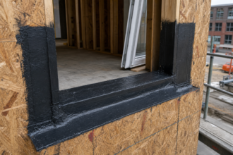
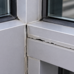
The Transition Details That Fail Most Often and the Mechanics Behind Each Failure
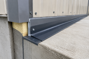
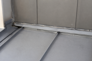
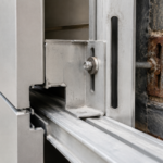
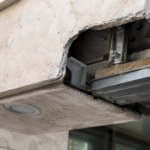
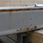
Floor-line transitions are the highest-frequency failure location on CMU backup wall assemblies. Where the fluid-applied membrane must bridge from the CMU face across a shelf angle or spandrel beam, three problems converge at the same point: differential movement between the masonry and the structure, a substrate change from CMU to steel or concrete and a membrane termination that must remain airtight under decades of thermal cycling.
Bridging membrane over a metal edge without backer rod and compatible sealant detailing at the termination is a primary failure point. The membrane edge lifts under positive pressure because it has no mechanical engagement with the substrate and no flexibility reserve at the transition.
The correct detail requires a termination bar mechanically fastened to the CMU at the upper edge of the membrane, a compatible sealant at the termination bar to prevent edge lifting and a transition membrane or flashing that bridges from the CMU face to the shelf angle with enough material reserve to accommodate the differential movement that will occur between the masonry and the structural frame over the service life of the building. Projects that skip the termination bar because it adds a line item to the air barrier installer’s scope are trading a small cost avoidance for a failure that is nearly impossible to remediate from the exterior after cladding is installed.
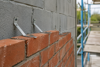
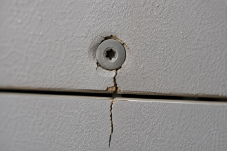
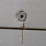
Penetration transitions fail for a different reason. Anchor tie holes, conduit sleeves and structural embed plates interrupt the CMU surface and create point-source air leakage.
Fluid-applied membranes applied over these penetrations without pre-treatment bridge the void but do not fill it. Thermal cycling cracks the bridged membrane at the penetration perimeter within the first heating season.
The correct sequence is hydraulic cement fill or compatible sealant to eliminate the void, followed by mesh reinforcement set in the first membrane coat, followed by the full membrane application. That sequence adds time and material cost.
It is frequently skipped. On a mid-rise office building I reviewed in the Southeast, anchor tie holes at 16 inches on center vertically and 24 inches on center horizontally across a full CMU backup wall elevation produced measurable point-source leakage at nearly every location.
The membrane had been applied in a single pass over the untreated holes and the bridged membrane had cracked at the hole perimeter within the first winter. The total open area was small at each individual penetration, but the aggregate leakage across the full elevation was sufficient to account for a significant portion of the building’s total air leakage failure.
Head-of-wall transitions are left to field judgment more often than any other detail in my experience. Without a defined termination bar, a compatible sealant and a compression seal at the underside of the structure above, the membrane edge lifts under positive pressure and the air control layer is broken at the top of every story.
ASTM E2357 tests air leakage at the assembly level and captures this failure mode where ASTM E2178 material testing cannot. Projects that test membrane material only and skip assembly-level verification are approving a component while leaving the assembly unvalidated.
The head-of-wall condition is particularly difficult to remediate after the fact because access requires removal of ceiling systems or interior finishes at every floor level and the remediation cost scales directly with the number of stories in the building.
Inside and outside corners concentrate stress in the membrane under thermal and structural movement. Most fluid-applied membrane manufacturers require mesh reinforcement at corners as a condition of warranty.
ABAA QA Program installation requirements specify reinforcement at penetrations and terminations as a minimum standard. Both requirements are routinely skipped in the field because they are not explicitly called out in the project specification and the installer has no contractual obligation to exceed what the spec requires.
The result is a warranty that is technically void at every corner on the building, a condition that neither the owner nor the design team typically discovers until a failure occurs and the manufacturer’s representative reviews the installation records.
The mechanical reality at corners is simple: the membrane wants to bridge the geometry change in a straight line, which means it lifts off the substrate at the inside radius of an inside corner and stretches at the outside radius of an outside corner. Without mesh reinforcement embedded in the wet membrane, both conditions produce cracks under the first significant pressure differential.
Primer Selection and the Absorption Rate Problem
Primer is not optional on high-absorption CMU. It is the mechanism that controls absorption rate and gives the fluid-applied membrane a consistent substrate to bond to.
The decision to prime or not prime should be driven by a field absorption test, not by schedule pressure or cost optimization. Primer adds a line item to the air barrier scope that is easy to cut during value engineering because its absence is not visible in the finished installation.
The consequences of that cut are deferred to the blower door test or, on projects without mandatory testing, to the first winter of occupancy when infiltration complaints begin.
A simple test: apply a few drops of water to the CMU face and observe absorption time. If the water absorbs in under 30 seconds, the block will pull moisture from the fluid-applied membrane faster than the membrane can cure uniformly.
That is a primer condition without exception. If the block absorbs water in 60 to 90 seconds, primer is still best practice.
If the surface rejects water at five minutes, the concern shifts from absorption to bond strength over a potentially contaminated or carbonated surface. Carbonation of the CMU surface, which occurs naturally as the block cures and reacts with atmospheric carbon dioxide, can reduce surface alkalinity enough to affect adhesion of certain membrane chemistries.
Membrane manufacturers should be consulted directly when block age exceeds 12 months or when the surface has been exposed to extended weathering before membrane application.
Primer selection must be confirmed compatible with the specific fluid-applied membrane system. Silane or siloxane penetrating sealers applied by a masonry contractor as a water repellent treatment will prevent membrane adhesion entirely.
This cross-trade contamination happens on projects where the masonry contractor applies a water repellent to protect the CMU during construction and nobody coordinates with the air barrier installer before membrane application begins. The water repellent is applied in good faith to prevent efflorescence and staining during the construction period.
The air barrier installer arrives weeks later, applies the membrane over what appears to be a clean CMU surface and produces an installation that has essentially no bond to the substrate. The failure is not detectable by visual inspection and may not appear in pull-off adhesion testing if the test locations happen to avoid the treated areas.
Specification language in Division 04 should explicitly prohibit water repellent treatment on CMU surfaces designated to receive fluid-applied air barrier membranes and that prohibition needs to be coordinated with the Division 07 submittals before either trade mobilizes.
What a Compliant Substrate Preparation Sequence Actually Looks Like
The preparation sequence for fluid-applied air barrier over CMU backup walls is not complicated. It is simply not specified often enough to be executed consistently.
The steps involved are well-established in manufacturer technical data sheets and ABAA installation guidance, but those documents are referenced rather than reproduced in most project specifications, which means the installer is expected to self-direct a preparation sequence that the contract documents never explicitly required.
Start with block finish and joint profile requirements written into Division 04: smooth-face or ground-face CMU where the air barrier plane falls on the exterior face, tooled concave mortar joints as a minimum requirement. If split-face is architecturally required on an interior wythe that carries the air barrier, the specification must acknowledge the additional preparation steps that follow.
Acknowledging the condition in the specification is not enough on its own. The specification must assign responsibility for the additional preparation work, define the acceptable preparation methods and establish a verification step before membrane application begins.
Without those three elements, the acknowledgment is decorative.
Pre-treat all penetrations, tie holes and embed plates with hydraulic cement or compatible sealant before membrane application. Apply primer at the rate and coverage the membrane manufacturer requires for the specific absorption class of the CMU.
The primer application rate for high-absorption block is typically higher than the rate for standard block and that difference should be reflected in the project specification rather than left to the installer’s judgment in the field. Apply the first membrane coat and embed mesh reinforcement at all inside corners, outside corners and penetration perimeters while the coat is still wet.
The mesh must be fully embedded with no dry edges, which requires the installer to work in manageable sections rather than applying membrane across a large area and returning to embed mesh after the coat has begun to skin over. Apply the full membrane system to the manufacturer’s minimum dry film thickness, which is commonly 20 to 40 mils depending on the product and verify film thickness with a wet film gauge during application rather than relying on coverage rate calculations alone.
Coverage rate calculations assume uniform absorption and uniform surface texture. Neither condition exists on CMU backup walls and wet film gauge readings are the only reliable verification method in field conditions.
That sequence is not extraordinary. It is the baseline for achieving the performance the code requires.
The Forward Obligation
The projects that will fail their blower door tests next year are under construction right now and the specifications driving those failures were written without this coordination. The fix is not a new product category or a more expensive membrane.
It is Division 04 language that controls the substrate and Division 07 language that requires preparation steps matched to the actual block finish and joint profile specified.