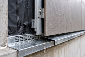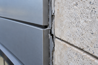


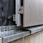
- Split-face CMU surface relief exceeding three-quarters of an inch makes continuous sealant adhesion physically impossible on standard mortar joints.
- ASTM C1193 and TMS 602-22 both assume planar substrates and provide no guidance for fractured masonry face profiles.
- Water infiltrates through capillary pathways behind the sealant bead and freeze-thaw cycling accelerates face shell spalling in a compounding loop.
- Forensic diagnosis requires pull testing per ASTM C1521 and quantified surface relief measurements to distinguish substrate failure from material failure.
- Specifications must add surface profile tolerances and mock-up adhesion testing requirements to break the cycle of repeat repair failures.
Split-Face CMU Facades: Why Sealant Repairs Keep Failing
A forensic investigation on a 2003-vintage split-face CMU community college building reveals the third consecutive sealant repair campaign has failed within 18 months. Not because of poor workmanship.
Because the substrate geometry made durable adhesion physically impossible from the first application. The irregular fractured face shell surface, with relief variations exceeding ¾ inch across a single unit width, left sealant bridging voids rather than bonding to a continuous substrate.
This scenario is repeating across hundreds of aging institutional buildings in northern climate zones and the industry has yet to produce a specification framework that addresses it directly.
Why Split-Face CMU Became the Dominant Institutional Facade Material: and Why That Now Matters
Split-face CMU peaked in institutional and light commercial construction from roughly 1985 through 2008. Low first cost, perceived durability and aesthetic versatility drove adoption across school districts, community colleges, municipal facilities and mid-rise commercial buildings throughout IECC Climate Zones 4 through 7. The result is an enormous building stock now 15 to 40 years old, placing these assemblies squarely in the first and second major envelope rehabilitation cycles.
The timing compounds the problem. Original sealant joints installed at construction, typically polyurethane or silicone with rated service lives of 20 to 25 years, are reaching end of life simultaneously with freeze-thaw deterioration of face shells.
Owners who deferred maintenance through the 2008 recession and subsequent budget cycles are now confronting simultaneous failures across every joint type on the facade. A school district managing 12 buildings constructed between 1992 and 2004 faces the realistic prospect of needing envelope rehabilitation on every structure within the same five-year capital planning window, with budgets that were sized for sequential rather than concurrent intervention.
ASTM C90, the governing standard for loadbearing concrete masonry unit manufacture, addresses compressive strength, absorption limits and dimensional tolerances. It contains no provisions for sealant joint geometry or surface profile tolerances at fractured faces.
That omission has allowed the problem to propagate invisibly through decades of construction without triggering a specification response. Manufacturers met the standard.
Contractors installed to the drawings. Specifiers referenced the correct ASTM designations.
The assembly still failed and no single party in the project delivery chain held a document that identified the incompatibility before water got in.
Insurance carriers are taking notice. Compounding claims from deferred maintenance intersecting with material fatigue are driving litigation cycles that building envelope consultants are increasingly being retained to untangle.
The forensic record in these cases consistently shows the same gap: a specification that addressed material properties without addressing substrate geometry compatibility.
The Surface Geometry Problem: What Makes Split-Face CMU Fundamentally Different from Smooth Masonry
The manufacturing process is the root cause. Hydraulic splitting of CMU produces fractured aggregate faces with peak-to-valley relief typically ranging from ¼ inch to over ¾ inch, depending on aggregate size and mix design.
No two units are identical. The fracture plane follows aggregate boundaries, creating a surface that is simultaneously concave, convex and undercut across a single unit face.
This is not a quality control failure. It is the intended product.
The visual character that made split-face CMU commercially attractive, that rough-hewn texture suggesting quarried stone, is produced by exactly the same mechanism that makes durable sealant adhesion geometrically improbable.
ASTM C1193, the Guide for Use of Joint Sealants, establishes substrate condition requirements in Section 5.3 and joint width-to-depth ratios in Section 7. 2.
Both sections assume a planar or near-planar substrate at the joint face. Split-face units violate this assumption at the unit-to-mortar interface and neither section provides exception language or modified procedures for irregular masonry substrates.
The standard was not written for this application. The industry applied it anyway.
No addendum, no errata and no companion guide document has addressed the gap in the decades since split-face CMU became a dominant facade material.
The consequences are predictable. A nominal ⅜-inch mortar joint becomes effectively variable in exposed width when measured against the fractured face plane.
Consistent backer rod placement is geometrically impossible; the rod seats against aggregate protrusions and bridges across recesses, leaving unsupported sealant spanning voids rather than bearing against a continuous substrate. Achieving the 1:2 depth-to-width ratio specified in C1193 Section 7.2 requires measuring from a reference plane that does not exist on a split-face unit.
In practice, installers measure from the nearest aggregate protrusion, which produces correct depth at that point and wildly incorrect depth everywhere the surface recedes behind it.
Tooling mechanics fail for the same reason. Standard concave or V-tooling requires continuous contact pressure across the joint face to consolidate mortar and create a dense, weather-resistant surface.
Fractured surface relief breaks contact at aggregate protrusions, leaving untooled voids scattered across the joint face. These voids are the primary initiation points for every failure mode that follows.
A skilled mason tooling a smooth CMU joint produces a consistent, dense surface. That same mason tooling an identical joint at a split-face unit produces a result that looks acceptable from three feet away and is functionally discontinuous at the bond line.
How Water Finds Its Way In: The Failure Pathway Anatomy
The primary entry points are not through the sealant field. They are at the sealant-to-CMU bond line, where adhesion is discontinuous because surface relief voids prevent contact between sealant and substrate across significant portions of the joint face.
Sealant that appears intact from the exterior is bonded only at aggregate contact points, with unbonded spans bridging the recesses between them. A probe test at the sealant perimeter on a joint that passed visual inspection will frequently reveal void depths of ¼ inch or more extending behind the sealant bead across 30 to 50 percent of the joint length.
The sealant looks fine. It is not doing anything.
Capillary wicking does the rest. Water trapped in the void space between sealant and fractured face migrates laterally and inward along the mortar joint plane, bypassing the sealant entirely.
The mortar joint, even when properly tooled at accessible surfaces, provides a continuous capillary pathway behind the sealant bead. The sealant becomes irrelevant as a water control layer once this pathway is established.
This is why interior water staining patterns on split-face CMU buildings frequently appear at locations well removed from the visible exterior joint and why owners and contractors spend years chasing leaks that cannot be correlated to any obvious exterior defect.
Freeze-thaw amplification accelerates the deterioration sequence. Water retained in face shell voids and sealant-substrate interface voids undergoes approximately 9% volumetric expansion at phase change, progressively fracturing the bond line and spalling face shells.
ASTM C666 freeze-thaw cycling data is relevant here, with one significant limitation: C666 evaluates freeze-thaw resistance on intact concrete specimens, not on fractured split-face profiles. Field performance in sealant void conditions, where water is trapped against the fractured surface and cannot drain, is not captured by standard testing.
The standard is not wrong. It is simply answering a different question than the one the field is asking.
A split-face unit that passes C666 testing as a manufactured product can still accumulate water in sealant interface voids and experience accelerated face shell spalling under field conditions that the test protocol never replicates.
The compounding deterioration sequence follows a consistent pattern: initial micro-void leads to water infiltration, which drives freeze-thaw spalling, which enlarges the void, which accelerates sealant debonding, which allows bulk water intrusion. Each repair campaign that ignores substrate geometry resets the clock without breaking the cycle.
The community college building referenced in the opening of this article had three repair campaigns documented in the project record. Each one specified polyurethane sealant, each one referenced C1193 and each one failed at the sealant-to-CMU bond line within 18 months.
The substrate was never modified. The specification never required it.
What Standard Masonry Specifications Get Wrong: The Gap in TMS 402 and Project Specifications
TMS 402-22 and its companion TMS 602-22 address structural performance and mortar joint workmanship in detail. Article 3.3 of TMS 602-22 specifies tooling requirements that apply uniformly regardless of unit face texture.
There is no provision specific to sealant joint preparation, surface profile accommodation or mock-up testing at textured CMU faces. The standard treats a split-face unit and a smooth-face unit as equivalent substrates for joint finishing purposes.
They are not. The tooling requirement in Article 3.3 was developed for smooth and ground-face masonry applications where continuous tool contact is achievable.
Applying it to split-face units without modification produces compliant documentation and non-compliant field results simultaneously.
The Division 04 and Division 07 coordination gap compounds the problem. MasterFormat Section 04 20 00 (Unit Masonry) and Section 07 92 00 (Joint Sealants) are typically written by different specifiers, reviewed independently and coordinated, if at all, only at the submittal stage.
Neither section owns the problem of substrate geometry incompatibility. The masonry spec references ASTM C270 for mortar and ASTM C90 for units but does not require surface profile measurement, mock-up adhesion testing or modified joint preparation procedures for split-face applications.
The sealant spec references C1193 and lists approved products but assumes a substrate that meets C1193 Section 5.3 requirements. The gap between those two sections is where water enters the building.
Project architects reviewing submittals at the construction stage are not positioned to catch this problem. The masonry submittal shows compliant units.
The sealant submittal shows a listed product with appropriate elongation and adhesion properties. Nothing in either submittal document triggers a review of whether the two systems are compatible at the substrate level.
The incompatibility is a design and specification problem, not a submittal problem and it cannot be caught at the submittal stage because it was never documented as a requirement.
The forensic implication is direct. Absence of specification language means contractors performing repairs have no contractual basis for requiring substrate modification.
Owners have no benchmark against which to evaluate repair quality. When the third repair campaign fails, no one in the project record ever documented that the substrate was unsuitable for the specified repair approach.
The specification gap becomes a liability gap. Consultants retained for forensic investigation on these buildings consistently find the same documentation pattern: correct product selections, correct installation references and a complete absence of any substrate compatibility evaluation specific to split-face geometry.
This is a solvable problem at the specification level. It requires someone to own it.
Forensic Investigation Protocol: How to Diagnose Sealant Failure Mode on Split-Face CMU
Diagnosing failure mode correctly determines whether a repair strategy has any chance of succeeding. Start with a systematic visual and tactile survey that maps sealant condition by failure type across the entire facade.
Adhesive failure at the CMU face, cohesive failure through the sealant body and adhesive failure at the mortar joint face are distinct failure modes with distinct causes and they require different responses. A facade survey that records only “sealant failure” without distinguishing failure mode provides no actionable information.
The repair specification that follows from an undifferentiated survey will be wrong for a significant portion of the facade regardless of what it specifies.
Adhesive failure at the CMU face is the signature failure mode for split-face geometry problems. Pull testing per ASTM C1521 at representative locations documents bond strength and failure plane.
Failures occurring at less than 40 psi consistently at the sealant-to-CMU interface, with the failure plane showing discontinuous contact patterns matching aggregate relief, confirm that substrate geometry is the primary variable. Failures occurring cohesively through the sealant body indicate material selection or installation deficiency rather than substrate incompatibility.
Distinguishing between these two failure modes in the field requires pull testing at a statistically meaningful sample, not visual observation alone. A minimum of five pull tests per facade elevation, distributed across different exposure orientations and unit types, provides a defensible dataset.
Fewer than that produces conclusions that opposing experts will challenge successfully.
Probe testing with a thin stainless wire at the sealant perimeter reveals void extent behind the sealant bead. Infrared thermography during appropriate delta-T conditions maps moisture distribution in the assembly and identifies face shell saturation zones that correlate with sealant discontinuities.
A minimum 10-degree Fahrenheit delta-T between interior and exterior is generally required to produce thermal contrast sufficient for reliable interpretation on masonry assemblies. Borescope inspection at select removed sealant sections documents the void geometry directly and provides photographic evidence of the sealant-to-substrate contact pattern that no other diagnostic method can replicate.
Document surface relief with a depth gauge or feeler gauge at minimum ten units per facade elevation. Record peak-to-valley measurements and calculate the percentage of joint face area where relief exceeds the sealant thickness.
This quantifies the geometric incompatibility rather than leaving it as a qualitative observation, which matters when you are writing a report that will be read by attorneys. A finding that states “surface relief was observed to be irregular” is an opinion.
A finding that states “peak-to-valley relief measured between 0.31 and 0. 74 inches across 47 units surveyed, with relief exceeding sealant thickness at 68% of measured locations” is a documented condition.
The distinction determines whether the report survives expert challenge.
Repair Strategy Options: What Actually Works and What Does Not
Sealant-over-sealant repairs fail on split-face CMU. This is not an opinion.
It is the documented outcome of every repeat repair campaign on geometrically incompatible substrates. The new sealant inherits the void geometry of the original installation and adds a second bond line failure point.
Do not specify it. Owners who push back on this conclusion because sealant-over-sealant is cheaper need to understand that the cost comparison is between a lower-cost repair that will fail in 18 months and a higher-cost repair that has a reasonable chance of lasting 15 years.
The lifecycle cost arithmetic is not close.
Complete sealant removal followed by substrate profiling is the minimum intervention that has a chance of producing durable results. Grinding aggregate protrusions to reduce peak-to-valley relief to under ¼ inch across the joint face width creates a substrate that approaches C1193 Section 5.3 compatibility.
This is labor-intensive, produces significant dust requiring containment and worker protection per OSHA silica exposure standards under 29 CFR 1926.1153 and alters the facade appearance at treated joints. Owners resist it.
The alternative is a fourth repair campaign. Specifiers who present this tradeoff clearly, with documented failure history and lifecycle cost projections, find that owners accept substrate profiling at a higher rate than those who simply specify it without explanation.
The specification narrative matters.
Elastomeric coating systems applied over the full CMU face, rather than sealant in discrete joints, transfer the water control function from a joint sealant to a surface membrane. This approach sidesteps the geometry problem entirely by making the joint face irrelevant to water penetration resistance.
Products in this category include high-build elastomeric masonry coatings meeting ASTM D6083 performance requirements, applied at film builds sufficient to bridge the joint and span surface relief without tearing under thermal movement. The tradeoffs are real: coating systems require periodic reapplication on cycles of 10 to 15 years depending on exposure, alter facade appearance significantly and can trap moisture in the assembly if applied over saturated substrates.
Moisture content verification per ASTM D4263 before coating application is not optional. Applying an elastomeric coating over a saturated split-face CMU assembly accelerates the freeze-thaw deterioration it was intended to prevent by sealing water into the face shell rather than allowing it to drain.
For assemblies with significant face shell spalling, the repair sequence must address structural integrity before addressing water control. Spalled face shells that have lost section cannot be patched to restore freeze-thaw resistance; replacement units or full-depth repair mortars meeting ASTM C270 Type S requirements are the appropriate response.
Color-matching replacement units on 20-year-old split-face CMU is genuinely difficult. Aggregate sources change, pigment formulations shift and weathering produces color variation that new units cannot replicate.
Owners need to understand this before the repair contract is executed, not after the replacement units arrive on site and the color match is visibly wrong from 50 feet.
Writing Specifications That Actually Address the Problem
The specification gap is fixable and fixing it is the most durable intervention available to building envelope consultants working on these buildings. The fix requires three things: a surface profile requirement, a mock-up adhesion testing protocol and explicit division of responsibility between the masonry and sealant sections.
Add a surface profile provision to Section 04 20 00 that requires peak-to-valley relief measurement at split-face joints before sealant installation and establishes a maximum relief tolerance of ¼ inch as a condition of sealant substrate acceptance. Reference ASTM C1193 Section 5.3 explicitly and note that split-face CMU does not meet that section’s substrate condition requirements without surface preparation.
This gives the contractor a specification basis for requiring grinding and gives the owner a benchmark for acceptance. Without this language, the contractor has no contractual standing to stop work and request direction when the substrate is incompatible.
The work proceeds, the sealant fails and the contractor is blamed for a condition the specification created.
Add a mock-up requirement to Section 07 92 00 that requires field adhesion testing per ASTM C1521 on a minimum 10-linear-foot mock-up before proceeding with production sealant installation. Establish a minimum pull-off strength of 50 psi with failure in the sealant body rather than at the bond line as the acceptance criterion.
If the mock-up fails, the specification has identified the problem before it propagates across the entire facade rather than after. The cost of a failed mock-up test is the cost of the test.
The cost of a failed production installation is the cost of the entire repair campaign plus the consequential damage from continued water infiltration during the period between installation and failure discovery.
Add a coordination note to both sections that explicitly identifies split-face CMU substrate geometry as a condition requiring joint review between the masonry contractor and the sealant installer before installation begins. This does not require a new specification section.
It requires two sentences in each existing section that point to the other. The absence of those sentences is what allows each contractor to complete their scope of work in full compliance with their individual specification section while the assembly fails at the interface between them.
The buildings that will fail next are already built. The specification language that prevents the generation after that from repeating this cycle needs to be written now and it needs to be written by the consultants who have seen what happens when it is missing.