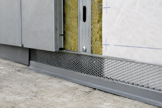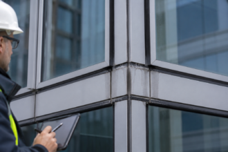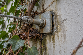
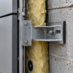
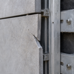
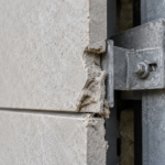
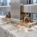
- A forensic investigation of a 2013 mid-rise found corroded fasteners and delaminated board consistent across three elevations and two separate framing crews, pointing to the substrate, not workmanship, as the cause.
- Failed boards tested at 8 to 15 percent chloride content by mass. Post-failure industry guidance caps safe chloride content at 0.5 percent.
- The ICC-ES evaluation reports specifiers relied on (issued under AC219) never tested for chloride content at all. Code compliance and long-term durability were never the same claim.
- Internal manufacturer records show chloride concerns were flagged as early as 2012, while sales teams kept quoting active evaluation reports without disclosing it, now a central issue in ongoing litigation.
- Boards above 2 percent chloride should be treated as presumptively failed. The board itself acts as a permanent chloride reservoir, so sheathing-only repairs without addressing it are a postponement, not a fix.
MgO Sheathing Failures: What the Chemistry Told Us
A forensic investigation team opens a rainscreen cavity on a 2013-vintage mid-rise in the Pacific Northwest and finds orange-stained framing, corroded screw shanks reduced to half their original diameter and MgO board faces that have delaminated into a chalky paste. The damage pattern is consistent across three elevations and two framing contractors.
That last detail matters. When the failure signature ignores installation crew boundaries, the substrate is the common variable.
The project is in active litigation. The owner’s expert has subpoenaed the original product data sheets and the manufacturer’s response has been to question installation workmanship.
That defense will not survive the fastener corrosion data.
What MgO Board Was Supposed to Solve
Between 2008 and 2014, magnesium oxide board entered the North American market with a straightforward value proposition: fire resistance comparable to Type X gypsum, dimensional stability superior to OSB and glass-mat gypsum and moisture resistance that theoretically made it suitable for rainscreen and EIFS substrates without the face-paper vulnerability of standard sheathing products.
Manufacturers positioned MgO board as a code-compliant substitute under IBC Section 2510.6, which governs substrate requirements for EIFS assemblies and supported that positioning with ICC-ES evaluation reports issued under AC219, the Acceptance Criteria for Cementitious Wood Fiber Sheathing Panels. The problem was that AC219 did not establish chloride content thresholds as an evaluation parameter.
The acceptance criteria addressed structural performance, dimensional stability and fire resistance. Chloride ion concentration, the single most consequential variable in long-term durability, was simply not part of the evaluation framework.
Adoption accelerated during the lumber price volatility of the early 2010s. Mid-rise Type III and Type V construction projects needed a cost-competitive sheathing option and MgO board filled that gap.
No unified ASTM product standard existed at the time of adoption. Specifiers relied on ICC-ES evaluation reports as their due diligence.
That reliance was reasonable given the information available. It was also catastrophically wrong.
The value proposition carried real weight in specific project types. High-rise residential and mixed-use buildings in Climate Zones 4 through 6 were the primary adoption targets, where continuous insulation requirements under ASHRAE 90.1-2010 pushed designers toward thinner, higher-performing sheathing assemblies.
MgO board’s density and dimensional stability made it attractive for EIFS assemblies where the substrate needed to carry both the adhesive-applied insulation board and the finish coat without telegraphing deflection. Structural engineers appreciated the published shear values.
Envelope consultants appreciated the published water absorption data. Nobody was testing chloride content because the evaluation framework did not require it and the failure mode had not yet appeared in the field record.
The marketing materials from this period are now exhibit documents in multiple lawsuits. They consistently cited the ICC-ES evaluation reports as evidence of code compliance and third-party validation.
That framing was technically accurate and practically misleading in equal measure. An ICC-ES evaluation report confirms that a product meets the specific criteria in a specific acceptance criteria document.
It does not confirm that the product is free of failure mechanisms that the acceptance criteria did not test for. That distinction, obvious in retrospect, was not obvious to the specifiers who treated the ESR as a complete product endorsement.
The Chloride Problem: Chemistry Behind the Failures
The failure mechanism is not complicated once you understand the manufacturing context. MgO board produced during this period, predominantly in Chinese facilities supplying North American projects, used magnesium chloride (MgCl2) as a binder component.
Excess MgCl2 was a cost-reduction practice. The boards passed short-term performance evaluations because chloride-induced corrosion is a time-dependent process that does not manifest quickly in controlled laboratory conditions.
MgCl2 is hygroscopic. It absorbs ambient moisture from the surrounding environment and, once in solution, releases chloride ions that migrate through the board matrix toward any metallic surface in contact with the panel.
Steel fasteners and light-gauge cold-formed steel framing are the primary targets. The corrosion mechanism involves both galvanic action, where dissimilar electrochemical potentials drive ion transfer and crevice corrosion concentrated at fastener penetrations where moisture accumulates and oxygen is depleted.
Rainscreen assemblies accelerate the damage. The open cavity creates vapor drive and wetting cycles that repeatedly wet and partially dry the board face, concentrating chloride migration at fastener locations with each cycle.
The assembly geometry that was supposed to protect the sheathing from bulk water intrusion actually intensified the electrochemical environment at every screw penetration.
Forensic testing of failed boards from Pacific Northwest projects documented chloride content ranging from 8% to 15% by mass in some samples. The industry guidance that emerged after the failures became undeniable recommended a threshold of no more than 0.5% chloride by mass.
For context, ASTM C1177, the standard specification for glass-mat gypsum substrate, does not permit the use of chloride-bearing binders at anything approaching these concentrations. The boards that failed were not marginal.
They were orders of magnitude outside any defensible threshold.
WTA Guideline 6-2, which addresses moisture-related damage mechanisms in wall assemblies, provides the theoretical framework for understanding how chloride concentration gradients develop under cyclic wetting conditions. The field data confirmed what the chemistry predicted.
The electrochemical sequence deserves closer attention because it explains why the damage pattern is so consistent across projects with different installation teams and different cladding systems. When MgCl2 dissolves in the moisture film that forms on the board surface under normal service conditions, the resulting solution has a chloride ion concentration high enough to break down the passive oxide layer that protects carbon steel fasteners.
Once that passive layer is compromised, active corrosion proceeds at a rate governed by the availability of moisture and oxygen rather than by any property of the fastener coating. Standard zinc-plated screws, which were the specified fastener in most of these assemblies, offered no meaningful resistance once the passive layer failed.
Hot-dipped galvanized fasteners performed better but not indefinitely. Projects where stainless steel fasteners were used for other reasons showed dramatically reduced fastener corrosion, which is itself a powerful forensic indicator: when the damage pattern correlates with fastener material rather than wall orientation, the corrosion source is the substrate, not the weather exposure.
The concentration gradient effect is equally important for understanding why the damage appears worse at fastener penetrations than at the board face. Chloride ions in solution migrate toward lower concentration zones.
The fastener shank creates a capillary pathway and a crevice geometry that concentrates both moisture and chloride ions. Oxygen depletion in the crevice shifts the local electrochemistry toward conditions that favor pitting corrosion, which is more destructive per unit area than uniform surface corrosion.
A screw shank reduced to half its original diameter by pitting has lost far more than half its load-carrying capacity because the remaining cross-section is irregular and stress concentrations at the pit margins accelerate fatigue failure under cyclic wind loading.
When the Field Reports Started Coming In
The earliest documented field complaints in North America appeared around 2011 and 2012, concentrated on Pacific Coast projects where marine exposure and high annual rainfall created the wetting cycles that accelerated chloride migration. By 2014, BC Housing’s Research Centre had published technical bulletins flagging MgO sheathing as a category of concern and the British Columbia Building Code technical community was actively discussing the issue.
The industry response was fragmented and, in some cases, deliberately quiet. Some manufacturers issued revised installation instructions emphasizing sealant at fastener heads and limiting exposure duration before cladding installation.
Others withdrew products without public announcement. No coordinated recall or advisory came from a single authoritative body.
The absence of a governing ASTM product standard meant there was no standards organization positioned to issue a formal product alert.
Specifiers continued using MgO board through 2017 and 2018 in some markets because ICC-ES evaluation reports for specific product lines remained active. ESR-2061, one of the more widely cited evaluation reports, was eventually withdrawn and that withdrawal date now functions as a documented marker in litigation: what did the manufacturer know before that date and what did they communicate to the design community?
The answer, in most cases, is that the manufacturer knew considerably more than they disclosed.
The gap between field evidence and specification practice is the central liability issue. Architects who specified MgO board in 2015 or 2016 based on an active ESR had a reasonable argument for reliance on the evaluation report.
That argument weakens significantly for projects specified after 2016, when the BC Housing reports were publicly available and the pattern of ESR withdrawals was visible to anyone paying attention.
The 2014 BC Housing bulletin was not an obscure document. It was distributed through provincial building official networks and referenced in continuing education materials offered through the Architectural Institute of British Columbia.
Design professionals practicing in Washington, Oregon and California who maintained active relationships with Canadian counterparts had access to the information. The question that expert witnesses in these cases must answer is not whether the information existed but whether a reasonably diligent design professional in that market and time period would have encountered it.
Courts have generally found that the answer shifts from “no” to “yes” somewhere between 2015 and 2017 depending on the jurisdiction and the specific project type.
The manufacturer communication record from this period is particularly damaging in litigation. Internal technical memoranda produced through discovery in several cases show that quality control personnel identified elevated chloride content in production batches as early as 2012. The response in most cases was to tighten incoming raw material specifications on paper without implementing the testing protocols necessary to verify compliance.
Sales teams continued quoting active ICC-ES evaluation reports without disclosing the internal quality concerns. That sequence, documented in email chains and meeting minutes, is the factual foundation for punitive damage claims in the cases that have proceeded to trial.
The field complaints themselves followed a predictable geographic pattern that tracked rainfall intensity and marine exposure rather than installation practice. Projects within two miles of saltwater showed accelerated damage timelines, but the underlying failure mechanism was identical to inland projects.
The marine environment added ambient chloride loading on top of the board-sourced chloride, compressing the timeline from first installation to visible failure from roughly four to six years down to two to three years in the most exposed locations. That geographic gradient is now a standard element of the forensic analysis: damage timeline relative to coastal proximity provides an independent check on the chloride source attribution.
Forensic Investigation Protocol: How to Confirm MgO-Related Damage
Visual indicators are consistent enough across projects that an experienced investigator can form a preliminary hypothesis before any testing begins. Orange or brown staining at fastener locations is the signature finding.
Efflorescence on the board face indicates chloride migration. Surface delamination producing a chalky or paste-like texture confirms binder breakdown.
Framing discoloration visible through the cavity, ranging from rust-orange to black depending on the steel alloy and exposure duration, indicates that corrosion has progressed beyond the fastener shanks to the framing members themselves.
Sampling protocol requires extracting board cores for chloride ion content testing adapted from ASTM C1152, the standard method for acid-soluble chloride content in concrete. The adaptation for MgO forensics is straightforward and well-established in current practice.
Swab testing of framing surfaces for chloride surface concentration provides a complementary data point that helps establish the migration pathway from board to substrate.
Fastener pull-out testing per ASTM E1190 is mandatory for any assembly where structural capacity is in question. Compare measured values against the code-required design values under AISI S240-15, the North American Standard for Cold-Formed Steel Framing.
Section B1 of that standard establishes the design basis for framing member capacity; when pull-out values fall below the design threshold, the assembly has lost structural integrity that cannot be recovered through surface treatment.
Documentation for litigation support requires strict chain of custody for all physical samples, a photographic protocol that correlates damage severity to wall orientation and compass exposure and a written log that maps damage patterns to the original installation timeline. Damage that is more severe on west and south elevations, where solar-driven vapor and wetting cycles are most intense, provides powerful evidence that the failure mechanism is moisture-driven rather than installation-error-driven.
The sampling grid matters as much as the sampling method. A minimum of three board cores per elevation, extracted at locations that include both fastener-adjacent and field zones, gives the laboratory enough data to characterize the chloride distribution across the panel rather than just at the most visually damaged points.
Manufacturers defending against chloride claims will argue that the investigator cherry-picked the worst samples. A systematic grid with documented sampling locations and GPS coordinates eliminates that argument.
Photograph each core location before extraction, during extraction and after the core is bagged and labeled. The chain of custody documentation begins at the wall, not at the laboratory receiving desk.
Framing section loss measurement requires removing fasteners and using digital calipers to measure the remaining shank diameter at the point of maximum corrosion, which is typically at the board face plane where the crevice geometry concentrates attack. Record both the measured diameter and the nominal specified diameter from the original construction documents.
Calculate section loss as a percentage and document it in a table that correlates fastener location to wall elevation, height above grade and proximity to penetrations or transitions. That table becomes a primary exhibit in the structural engineer’s assessment of remediation scope.
Infrared thermography during a heating cycle can identify moisture-laden zones in the assembly that are not yet visible through the cladding. This is particularly useful on projects where the cladding is still in place and selective opening is necessary to control investigation cost.
Areas showing anomalous thermal signatures should be prioritized for physical investigation. Confirm thermographic findings with a calibrated moisture meter reading taken through a small probe hole before committing to a full opening.
The combination of thermographic mapping and targeted physical investigation gives the forensic team a defensible basis for extrapolating damage extent across unopened wall areas, which is essential for developing a remediation cost estimate that will survive scrutiny in mediation.
Remediation Scope Decisions: Partial Repair vs. Full Replacement
The decision framework for remediation scope hinges on two measurements: fastener pull-out test results relative to AISI S240-15 design values and framing section loss as a percentage of design thickness. Boards showing chloride content above 2% by mass should be treated as presumptively failed regardless of visual condition.
The chemistry is too far advanced to trust surface appearance.
When framing section loss exceeds 15% of design thickness, the structural engineer of record must be involved before any remediation plan is finalized. AISI S100-16 Section A2 establishes the design basis for cold-formed steel members; section loss at that threshold affects load path integrity in ways that a sheathing replacement alone cannot address.
This is not a judgment call for the envelope consultant to make unilaterally.
Sheathing-only replacement is defensible when fastener pull-out values remain within 20% of design minimums and framing section loss is below 10%. Localized repair, meaning selective fastener replacement and board patching, is rarely appropriate on projects with the damage pattern described here.
The chloride contamination is assembly-wide, not localized.
On occupied mid-rise projects, phased remediation sequencing must maintain continuous weather protection. Temporary cladding or heavy-duty housewrap detailing at the perimeter of open sections is not optional.
Statutes of repose for construction defect claims vary significantly by jurisdiction, with periods ranging from six to ten years in most western states and provinces. Filing deadlines for manufacturer warranty claims are typically shorter.
The forensic report is the legal instrument that preserves both remedies and it needs to be completed before either clock expires.
The 2% chloride threshold for presumptive failure is not arbitrary. At that concentration, the chloride ion supply in the board matrix is sufficient to sustain active corrosion on carbon steel indefinitely, even if the assembly is dried out and the cladding is replaced without addressing the substrate.
Investigators who have opened assemblies five years after a sheathing-only repair on high-chloride boards have found that the new fasteners into the old framing are already showing pitting corrosion. The board is the chloride reservoir and it does not deplete on a human-relevant timescale.
Any remediation plan that leaves high-chloride board in place is not a repair; it is a postponement.
The framing replacement decision involves a cost calculation that the structural engineer and the owner need to make together with full information. Replacing corroded cold-formed steel studs in an occupied mid-rise is expensive and disruptive.
The temptation is to document the section loss, note that it is below the 15% threshold and move on. That approach is defensible when the section loss measurement is accurate and the remaining framing capacity has been verified against the actual design loads, including wind uplift on the cladding attachment system.
It is not defensible when the section loss measurement was taken at a single point on each stud rather than along the full height or when the measurement protocol did not account for pitting geometry. Pitting corrosion produces localized section loss that can be two to three times the average section loss measured by caliper.
A stud that measures 8% average section loss may have a pit that represents 20% local section loss at the critical buckling location. The structural engineer needs to know the measurement methodology, not just the numbers.
Replacement Substrate Selection: What the Specification Must Get Right
Approved replacement substrates for rainscreen and EIFS assemblies fall into three categories, each with specific performance characteristics and compatibility requirements that the specification must address explicitly.
Glass-mat gypsum sheathing meeting ASTM C1177 is the most straightforward replacement in terms of code compliance and EIFS system compatibility. The glass mat facing eliminates the face-paper moisture vulnerability of standard gypsum sheathing and the product carries a long track record with fluid-applied air and water barrier membranes.
Verify compatibility with the specific fluid-applied WRB product being specified; some silyl-terminated polyether membranes require a primed surface on glass-mat gypsum to achieve adequate adhesion and the required bond strength for ASTM E2357 compliance.
Fiber-cement sheathing is appropriate for rainscreen assemblies where the air control layer will be a mechanically attached sheet membrane rather than a fluid-applied product. Fastener corrosion resistance must be specified explicitly; the replacement assembly should use hot-dipped galvanized or stainless steel fasteners regardless of what the original installation used.
Exterior-grade gypsum fiber panels are gaining traction as a replacement substrate in markets where fire resistance ratings drive the specification. These products carry no chloride-bearing binder components and are evaluated under ASTM C1278. The water control layer detail at panel joints requires more attention than glass-mat gypsum because the panel edges are less tolerant of sustained moisture exposure.
Whatever substrate you select, the replacement specification must address four control layer continuity explicitly: water, air, vapor and thermal. The remediation is an opportunity to correct deficiencies in the original assembly that may have contributed to the wetting cycles that accelerated the MgO failure.
If the original air barrier detailing was deficient, fix it in the replacement scope. The cost of doing it right once is always less than the cost of the next investigation.
The projects still being litigated today share one common specification failure: the replacement substrate was selected for cost and availability without a written compatibility analysis for the fluid-applied membrane, the panel attachment system and the fastener type. Do not repeat that error.
The chemistry that destroyed the original assembly will find any weakness you leave in the replacement.
The compatibility analysis for glass-mat gypsum and fluid-applied membranes deserves specific attention because it is the step most frequently skipped under schedule pressure. ASTM E2357, the standard test method for determining the air leakage resistance of air barrier assemblies, requires that the membrane achieve a bond strength to the substrate that survives the cyclic pressure differentials in the test protocol.
Published bond strength data from membrane manufacturers is typically generated on a specific glass-mat gypsum product from a specific manufacturer using a specific primer. Substituting a different glass-mat gypsum product, even one that also meets ASTM C1177, can produce meaningfully different bond strength results if the surface texture, porosity or coating chemistry differs.
Request the membrane manufacturer’s written confirmation of compatibility with the specific substrate product and thickness being specified. Get it in writing before the submittal phase, not after the membrane is already on the wall.
Fiber-cement sheathing introduces a different set of compatibility considerations. The panel weight is substantially higher than glass-mat gypsum, which affects the design of the cladding attachment system and the spacing requirements for temporary support during installation.
The higher density also means that fastener withdrawal values are governed by the framing member capacity rather than the panel capacity in most configurations, which is an advantage when the framing has been verified as structurally adequate. The surface of fiber-cement sheathing is alkaline and some fluid-applied membranes show reduced long-term adhesion on high-pH substrates.
If the replacement design calls for a fluid-applied membrane over fiber-cement, the same compatibility verification process applies. The panel manufacturer and the membrane manufacturer both need to confirm the assembly in writing and the confirmation needs to reference the specific products, primer requirements and application conditions that will govern the actual installation.