Terracotta Rainscreen Panels in North American Commercial Facades: Attachment System Selection, Thermal Movement Tolerances and Where the Specification Gaps Create Long-Term Risk
A terracotta panel on a completed civic library project in the Upper Midwest begins rocking visibly in its clip during a post-occupancy inspection. Not cracked.
Not fallen. Just no longer restrained.
The installer had used the proprietary aluminum rail system specified by the panel manufacturer, but the project specification contained no requirement for thermal movement tolerance verification and the substituted clip profile had a tighter engagement depth than the original submittal. The failure mode was entirely predictable.
The specification gap that allowed it was not unusual at all.
Why Terracotta Is Back and Why the Attachment Question Is Now Urgent
Terracotta has re-entered serious institutional specification conversations for three converging reasons: lifecycle cost arguments that favor inert ceramic over coated metals, embodied carbon narratives that position kiln-fired clay favorably against aluminum composite systems and the aesthetic continuity terracotta provides on campuses and civic buildings with existing masonry context. Major manufacturers have reported expanded project pipelines in civic, higher education and transit sectors since approximately 2018 and the pattern is visible across the project types showing up in Division 04 and Division 07 submittals.
The material itself is well understood. Terracotta’s durability under freeze-thaw cycling, UV exposure and acid rain is documented across a century of building performance data.
That is not where the risk lives.
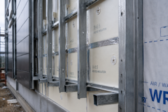
The risk lives at the interface between the panel and the substructure. The proprietary clip-and-rail attachment hardware ecosystem that supports modern terracotta rainscreen installation has outpaced specification practice significantly.
North America has no unified standard equivalent to the European ETAG 034 guideline for external wall cladding kits and neither NCMA guidance nor existing cladding industry literature fills that gap adequately. Specifiers are writing Division 07 sections around systems they cannot evaluate against a common performance baseline.
That regulatory vacuum has practical consequences that show up in submittals. When a specifier cannot point to a governing standard that defines minimum engagement depth, maximum rail span for a given climate zone or required cyclic load test protocol, the manufacturer’s installation guide becomes the de facto performance standard by default.
Installation guides are written to cover a broad range of project conditions, not to optimize for the specific thermal, wind and seismic demands of a particular project location. A guide written to cover projects from Miami to Minneapolis will not be conservative enough for Minneapolis and will not flag the corner zone loading conditions that a Chicago high-rise facade actually faces.
Specifiers who recognize this gap sometimes attempt to fill it by importing language from ASTM C1242 or from curtain wall specifications written under AAMA 501 protocols, but those adaptations require engineering judgment that the specification section itself rarely documents. The result is a Division 07 section that looks complete on its face and leaves the actual performance determination to the manufacturer’s submittal, which is written to demonstrate compliance with the specification as written rather than to address conditions the specification failed to anticipate.
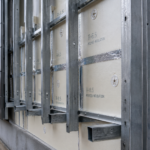
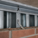
How Proprietary Clip-and-Rail Systems Actually Work and Where They Differ
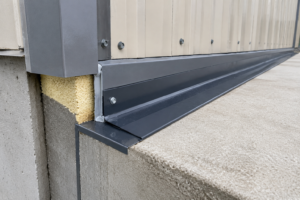
Three dominant attachment geometries cover the majority of terracotta rainscreen installations in North America. The first is an open-joint horizontal rail system using top-and-bottom kerf clips, where the terracotta panel is captured in a routed slot at its top and bottom edges and the clip engages a horizontal aluminum extrusion anchored back to the structural substrate.
The second is a concealed vertical rail system with side-slot engagement, where the panel integrates a slot along its vertical edge and engages a continuous or segmented vertical rail. The third is a hybrid approach using panel-integrated aluminum extrusions that are factory-bonded or mechanically attached to the terracotta and then clip directly to a subframe.
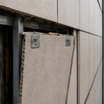
Panel engagement depth, the actual dimension of terracotta material captured within the clip profile, varies by manufacturer from as little as 8mm to over 20mm. This is a critical variable.
It rarely appears in project specifications. An 8mm engagement depth under a high-suction corner zone load is a fundamentally different structural condition than a 20mm engagement depth and the difference does not show up in a simple load table comparison.
Fixed-point versus floating-point attachment strategy matters equally. A fixed clip locks the panel against movement in all directions; a floating clip allows controlled slip in one axis.
The ratio of fixed to floating clips per panel governs how thermal and wind loads distribute through the assembly. Aluminum rail systems carry a thermal expansion coefficient of approximately 23 µm/m per degree Celsius.
Terracotta runs 5 to 7 µm/m per degree Celsius. That differential exists at every single clip interface in the assembly and it accumulates across every rail span.
ASTM C1242, the standard guide for dimension stone attachment systems, provides the closest applicable analogy for evaluating these interfaces, but it does not directly govern terracotta. Specifiers applying it by analogy are working without a direct regulatory basis.
The kerf geometry in top-and-bottom clip systems introduces a failure variable that does not appear in any standard load table. Terracotta kerfs are routed or extruded during manufacturing and the dimensional tolerance on kerf width and depth varies by manufacturer and by production run.
A clip designed for a 6mm kerf width will behave differently when installed in a panel with a 5.5mm kerf produced at the tight end of the manufacturing tolerance band. The clip engagement becomes stiffer, thermal slip is partially restricted and the stress concentration at the kerf root increases.
None of this is visible during installation and none of it is captured by a static load test conducted on a panel produced to nominal dimensions. Specifiers who require kerf dimensional tolerances to be reported on material certifications and who tie clip selection to the actual kerf dimensions rather than the nominal design dimension, are addressing a real variable.
That requirement appears in almost no project specifications currently in circulation.
The hybrid panel-integrated extrusion approach introduces a different set of variables. The bond or mechanical connection between the aluminum extrusion and the terracotta panel body becomes a load path element and the long-term performance of that connection under cyclic thermal loading is a function of the adhesive system used, the surface preparation of the terracotta and the coefficient of thermal expansion mismatch between aluminum and ceramic at the bond line.
Manufacturer test data for these systems typically covers initial bond strength under static load. Data on bond line fatigue after ten years of thermal cycling in a Zone 5 or Zone 6 climate is not routinely published and is not routinely requested in specifications.
Thermal Movement Tolerances Across North American Climate Zones
The numbers here are not abstract. An aluminum rail spanning 3.6 meters between fixed points in a Chicago installation, using ASHRAE 169-2020 Climate Zone 5A design temperatures and accounting for dark terracotta surface temperatures that can reach 30 to 40 degrees Celsius above ambient air temperature in full solar exposure, will expand and contract approximately 6.
6mm over a full annual cycle. Several common proprietary clip profiles publish slip tolerances below that value.
The rail moves more than the clip allows. Something has to give and what gives is clip engagement.
The distinction between air temperature delta and surface temperature delta is one that specifications almost never address. A specification that pulls design temperatures from ASHRAE 169-2020 Table 1 and applies them directly to rail movement calculations is already underestimating the thermal load on a south or west facade in a high solar gain climate.
Dark terracotta on a west-facing facade in Phoenix, ASHRAE Climate Zone 2B, reaches surface temperatures that compress the effective movement budget to a point where standard installation guide span recommendations become unsafe without adjustment.
Three climate zone pairings carry the highest risk in North American terracotta applications. Zone 6 and Zone 7 installations face severe cold combined with high annual delta-T values that drive maximum rail movement.
Zone 2B installations face extreme solar gain that pushes surface temperatures well beyond air temperature design assumptions. Coastal Zone 4C installations face a less obvious risk: moderate temperature cycling combined with persistent high humidity accelerates oxidation at aluminum clip contact surfaces, gradually increasing friction and interfering with the floating-point slip that the system depends on to relieve thermal stress.
Most proprietary installation guides specify maximum unsupported rail spans between fixed clip points, with published values typically ranging from 600mm to 1,200mm. Those figures are calculated against a moderate climate baseline.
They are not adjusted for project-specific climate zone conditions in the vast majority of project specifications.
The surface temperature premium calculation is not complicated, but it requires the specifier or facade engineer to make an explicit decision about facade orientation and terracotta color before the specification is issued. ASHRAE 169-2020 provides the extreme design temperatures.
The surface temperature premium for a dark-colored cladding panel in full solar exposure is well-documented in building science literature, with values commonly cited between 25 and 45 degrees Celsius above ambient depending on solar absorptance and wind speed at the facade surface. Applying a 35-degree Celsius surface temperature premium to the ASHRAE 169-2020 extreme high temperature for Phoenix, which runs approximately 43 degrees Celsius for Climate Zone 2B, produces a design surface temperature of roughly 78 degrees Celsius.
Running that value against the aluminum rail expansion coefficient over a 3.6-meter span produces a movement demand that exceeds the published slip tolerance of several widely specified clip profiles. The calculation takes less than ten minutes.
It is not being done on most projects.
The installation temperature assumption compounds the problem further. Rail movement calculations require a baseline installation temperature and most manufacturer guides assume an installation temperature near the midpoint of the expected service temperature range.
Field installation of terracotta panels in North American commercial construction does not reliably occur at the temperature the manufacturer assumed. A rail system installed in late fall in a Zone 6 climate at 5 degrees Celsius and then subjected to a summer surface temperature of 65 degrees Celsius experiences the full expansion range in one direction from the installation baseline, with no contraction reserve.
Clip profiles that were marginal at the midpoint assumption become inadequate under that scenario. Specifications that require the contractor to document installation temperature and verify that clip slip tolerances are adequate relative to the actual installation temperature baseline are addressing a real field condition.
That requirement is rare.
Wind Load Transfer and the Clip-to-Rail Interface Under Cyclic Loading
Terracotta panels in rainscreen assemblies must transfer both positive and negative wind pressure through the clip-to-rail interface. ASCE 7-22 Section 30.3 governs components and cladding wind pressures and the corner zone multipliers it requires produce unit pressures that are substantially higher than field zone values.
Corner and parapet zones are consistently where clip failures concentrate in post-failure investigations. This is not a coincidence; it is a direct consequence of specifying attachment systems against field zone loads and then installing them in corner zones without adjustment.
The fatigue mechanism is worth understanding precisely. Cyclic wind loading at clip contact points creates fretting wear on aluminum clip surfaces over time.
Each pressure cycle causes micro-slip at the contact interface. That micro-slip removes material.
Engagement depth decreases incrementally. The panel begins to rattle under moderate wind events before it becomes a life-safety hazard, which is actually useful as a warning sign if anyone is paying attention during post-occupancy maintenance.
Most proprietary system test reports are conducted under static or quasi-static load protocols per ASTM E330. ASTM E330 is a structural performance test for uniform static air pressure difference; it tells you the load at which a system fails under a single application. It tells you almost nothing about how the clip-to-rail interface degrades under ten thousand load cycles at 60 percent of that failure load.
Very few manufacturers publish cyclic fatigue data for clip interfaces. Specifications almost never require it.
The substitution risk compounds this problem directly. A substituted clip with equivalent static load ratings but different engagement geometry, reduced contact area or softer alloy hardness will perform differently under cyclic fatigue conditions.
None of those variables appear in a standard load table and “approved equal” language in a specification does not capture them.
The ASCE 7-22 corner zone pressure multipliers are not a minor adjustment. For a mid-rise building in Exposure Category C, the ratio of corner zone design pressure to field zone design pressure for components and cladding commonly runs between 1.5 and 2.
0 depending on building height and geometry. A clip-and-rail system specified against a field zone design pressure of 1.2 kPa may face a corner zone design pressure of 2.
0 kPa or higher at the same building. If the specification does not explicitly require that corner and parapet zone clip spacing be reduced or that a higher-capacity clip profile be used in those zones, the installation crew will apply the standard field zone layout throughout.
The installation guide does not distinguish between zones unless the specification requires that it does. Post-failure investigations on terracotta projects in coastal and high-wind exposure locations repeatedly find that corner zone panels were installed with field zone clip spacing.
The specification permitted it because the specification did not address it.
The alloy specification for aluminum clips is a variable that receives almost no attention in project specifications and carries meaningful consequences for both fatigue performance and galvanic compatibility. Aluminum clips are commonly produced in 6063-T5 or 6061-T6 alloy and the difference in hardness and fatigue resistance between those two alloys is significant.
A 6063-T5 clip and a 6061-T6 clip can carry identical static load ratings while exhibiting substantially different fretting wear rates under cyclic loading. When a substituted clip meets the load table requirement but is produced in a softer alloy, the fatigue degradation timeline compresses.
The panel that would have begun rattling after fifteen years of wind cycling begins rattling after eight. Specifying minimum alloy designation for aluminum clip components is a one-line addition to a Division 07 section.
It is absent from nearly every terracotta specification currently in practice.
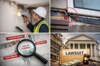
What Current Specifications Typically Get Wrong
Four specification gaps appear consistently in terracotta rainscreen projects that reach failure investigation. First, specifiers define panel material, finish and color without establishing attachment system performance criteria.
The Division 07 section references the manufacturer’s installation guide and stops there, which means the performance standard for the attachment system is whatever the manufacturer chose to publish, not what the project conditions require.
Second, “approved equal” substitution language on proprietary clips defines equivalency entirely through load ratings. Engagement depth, contact geometry and alloy specification are not listed as equivalency parameters because the original specification never defined them.
A procurement substitution that meets the load table passes the equivalency test and changes the actual performance of the assembly.
Third, climate-zone-adjusted rail span limits are absent from nearly every Division 07 terracotta section. The specification incorporates the manufacturer’s standard installation guide by reference and that guide’s span table was calculated for a climate baseline that may not match the project location.
A project in Minneapolis and a project in Atlanta may carry identical specification language while facing thermal movement conditions that differ by a factor of two.
Fourth, specifications rarely require third-party testing verification for the specific clip-and-rail combination being installed. Manufacturer test reports cover the system as originally designed and tested.
They do not cover substituted components, field-modified clip profiles or engagement depths reduced by installation tolerance accumulation. Requiring independent verification of the as-built attachment condition is not standard practice.
It should be.
A fifth gap appears less frequently in failure investigations but carries significant long-term risk: the absence of any maintenance inspection protocol tied to the warranty period. Terracotta panel warranties commonly run 10 to 25 years on the ceramic material.
Attachment system warranties from the same manufacturers typically run 5 to 10 years and contain exclusions for installation errors, substituted components and conditions outside the climate baseline assumed in the installation guide. The gap between the panel warranty term and the attachment system warranty term is not explained to building owners during the specification process and post-occupancy maintenance programs rarely include clip engagement depth verification at any inspection interval.
The rocking panel on the library project described at the opening of this article was discovered during a post-occupancy inspection that was conducted for unrelated reasons. No scheduled inspection would have caught it under the maintenance program the owner had in place.
Writing a minimum inspection protocol into the closeout documentation, with specific reference to clip engagement depth verification at corner and parapet zones, costs nothing at the specification stage and provides the early warning mechanism that the fatigue degradation process actually generates if someone is looking for it.
The Seismic Overlay That Most Facade Engineers Underweight
Seismic Design Category assignments under ASCE 7-22 create an additional performance requirement that terracotta attachment specifications frequently handle inadequately. In SDC C through F, nonstructural components including cladding assemblies require seismic design per ASCE 7-22 Chapter 13. The component importance factor and the applicable Rp and ap values for exterior nonstructural wall elements generate horizontal design forces that must be transferred through the same clip-to-rail interface that is already managing thermal movement and wind load.
The interaction between seismic drift accommodation and thermal movement accommodation is where specifications most commonly fail to establish clear performance requirements. A fixed-point clip that provides adequate seismic restraint may not allow the thermal slip that the rail span requires.
A floating-point clip that accommodates thermal movement may not provide adequate seismic restraint under Chapter 13 force levels. Resolving that conflict requires explicit engineering of the fixed-to-floating clip ratio for the specific climate zone and seismic design category combination.
It is not resolved by referencing the manufacturer’s standard installation guide, which is written for a generic condition.
The ASCE 7-22 Chapter 13 seismic force calculation for exterior cladding uses an ap value of 1.0 and an Rp value of 2.5 for typical exterior nonstructural wall panels, producing a horizontal design force that scales directly with the component weight and the spectral acceleration at the building site. For a terracotta panel assembly on a building in SDC D, which covers a substantial portion of the western United States and portions of the central and eastern seismic zones, the calculated horizontal force