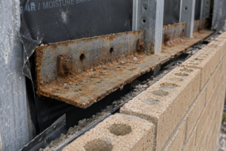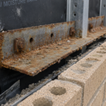


- Over 30% of veneer tie anchors pulled free in a post-earthquake inspection of a building that had passed all required code reviews.
- Prescriptive TMS 402-22 tie spacing was never calibrated for seismic out-of-plane demands in SDC C and above.
- ASCE 7-22 introduced a revised Fp equation that can increase calculated seismic demand on upper-floor veneer ties by 30% or more.
- Rebar reinforcement in the veneer wythe does not substitute for adequate tie anchorage and requires independent seismic calculation.
- Specifiers who document explicit Fp reconciliation per ASCE 7-22 Section 13.5.3 protect both the building and their professional liability.
Masonry Veneer Seismic Ties: Where Compliance Fails
A 2019 post-earthquake inspection of a four-story commercial building in the Puget Sound region revealed that over 30% of the masonry veneer tie anchors had pulled free from their CMU backup wall embedments. The ties themselves did not fracture.
The specified tie spacing had been calculated against gravity and wind loads only, with seismic out-of-plane demands treated as an afterthought. The building held a valid certificate of occupancy and had passed all required inspections.
Nobody had flagged the discrepancy between prescriptive compliance and actual seismic demand. That gap between “code compliant” and “seismically adequate” is where facade failures live and it is more common than the profession acknowledges.
Why Moderate Seismic Zones Are the Blind Spot in Veneer Tie Design
Seismic Design Category C gets treated as a near-miss by specifiers who cut their teeth on SDC A and B projects. The prescriptive tie schedules in TMS 402-22 feel familiar, the details look like what they have always drawn and nobody pushes back during plan review.
That false confidence is the problem.
The jump in out-of-plane seismic demand between SDC B and SDC C is not linear. The component force Fp scales with both the spectral acceleration Sds and the height ratio z/h, meaning a veneer panel at the third or fourth floor of a building in SDC C with Sds = 0.50g sees demands that dwarf what the prescriptive spacing was ever calibrated to resist.
The nonlinearity catches specifiers off guard every time.
Prescriptive compliance under TMS 402-22 Section 6.2 does not automatically satisfy ASCE 7-22 Section 13. 5.
3 component-level seismic demands for anchored veneers. These are separate obligations that must be reconciled, not alternatives.
Many facade consultants inherit tie layouts from structural engineers whose scope stopped at the backup wall and never extended to envelope performance criteria. That coordination gap is a systemic failure, not an individual one.
The problem concentrates in markets where SDC C is the ceiling rather than the floor. Specifiers working in coastal Pacific Northwest jurisdictions, the Intermountain West and parts of the central United States encounter SDC C as their routine condition.
They are not seismic specialists. They have not spent careers working through the implications of ASCE 7 Chapter 13 for nonstructural components.
They apply the prescriptive masonry standard because it is what the specification template contains and the plan reviewer confirms the masonry standard is satisfied without checking whether the component-level seismic demand calculation was ever performed. That review gap is structural.
It exists because the two obligations live in different code documents and the jurisdictional review process rarely connects them explicitly. Until that connection becomes a standard plan review checkpoint, the same failure mode will repeat.
How ASCE 7-22 Changed the Seismic Demand Calculation for Anchored Masonry Veneer
ASCE 7-22 Chapter 13 introduced meaningful changes to the nonstructural component force equation that specifiers working from ASCE 7-16 habits need to internalize. The revised Fp equation in Section 13.3-1 replaced the older linear interpolation method with a formulation that more accurately captures amplification at mid- and upper-story elevations.
The practical result is higher calculated demands on veneer ties at exactly the locations where facade failures tend to concentrate.
Consider a representative SDC C building: Sds = 0.50g, five stories, masonry veneer at the fourth floor where z/h = 0. 80. Under ASCE 7-16, the Fp calculation at that elevation produced a force on the order of 0.
40Wp. The revised ASCE 7-22 equation, applying the same Sds and z/h values with ap = 1.0 and Rpo = 1.
5 from Table 13.5-1, yields a demand closer to 0. 53Wp at that floor level.
That 30% increase in calculated demand is not trivial when you are already running a tie system that was barely adequate under the previous standard.
The selection of Rpo for masonry veneer tie systems matters enormously. Table 13.5-1 assigns values based on ductility and deformability of the connection system.
A stiff, non-ductile corrugated wire tie carries a lower Rpo than a ductile adjustable tie with positive attachment, which directly increases the calculated Fp demand. Specifiers who default to Rpo = 2.5 without confirming the tie system’s ductility classification are underestimating demand.
The ASCE 7-22 equation also introduces a floor amplification factor that was not present in the same form under the 2016 edition. That factor accounts for the dynamic amplification of acceleration through the building’s structural system and it produces meaningfully higher demands at upper floors than the older linear z/h interpolation did.
For a five-story building with a relatively stiff lateral system, the floor amplification factor at the fourth level can push the effective Fp well above what the linear method would have predicted, even holding Sds constant. Specifiers who have not worked through a side-by-side comparison of the two editions on an actual project tend to underestimate how significant that difference is in practice.
Jurisdictional adoption complicates this further. California’s CBC 2022 references ASCE 7-16, not ASCE 7-22. Washington State’s 2021 Building Code also references ASCE 7-16 with amendments.
The transition gap is real: designers working across state lines may be applying different editions of the underlying seismic standard to nearly identical buildings. Know which edition your jurisdiction has adopted before you finalize your tie spacing calculations.
The Mechanics of Out-of-Plane Tie Failure: What the Load Path Actually Looks Like
The seismic out-of-plane load path through an anchored masonry veneer assembly is straightforward to describe and surprisingly easy to disrupt. Seismic ground motion generates inertial forces in the veneer wythe proportional to its mass and the local floor acceleration.
Those forces must transfer through the tie into the CMU backup wall and then into the floor diaphragm. Every element in that chain has to perform.
Three distinct failure modes appear in post-event investigations. Tie wire fracture at the corrugated anchor bend occurs when the wire cross-section is undersized or the bend geometry creates a stress concentration under cyclic loading.
Anchor pullout from the CMU face shell is the most common failure mode in moderate seismic events, particularly where ties were embedded into mortar joints at the face shell without adequate depth. Veneer unit cracking at the tie bearing point occurs when the tie is too stiff to accommodate differential movement between the veneer and backup, concentrating demand at the masonry unit itself.
Tie stiffness and ductility govern how demand redistributes across the field of ties during a seismic event. A stiff, non-ductile tie transfers its full demand immediately with no capacity for redistribution.
When that tie fails, the adjacent ties pick up additional load in a progressive sequence that can cascade across a panel. A compliant tie system may allow displacement that exceeds acceptable limits before load transfer occurs.
Neither extreme is acceptable. The design target is a tie with controlled stiffness and documented ductility.
CMU face-shell thickness and mortar joint quality are as consequential as tie capacity. TMS 402-22 Section 6.2.2.3 establishes minimum embedment requirements, but embedment into a partially grouted CMU face shell with variable mortar consolidation does not reliably achieve the pullout resistance assumed in the design calculation.
ASTM A1008/A1008M governs the cold-formed steel wire material, but material compliance alone does not guarantee field performance when the substrate is inconsistent.
The cyclic loading character of seismic demand adds a failure mechanism that static wind load design does not capture. A tie that performs adequately under a single peak load event may degrade progressively under the repeated tension-compression reversals that characterize earthquake ground motion.
Corrugated wire ties are particularly susceptible to this degradation because the corrugation geometry that provides mechanical interlock under monotonic loading can act as a fatigue initiation site under cyclic loading. Adjustable two-piece ties with positive mechanical connection between the anchor section and the tie wire perform more predictably under cyclic demand, which is one reason TMS 402-22 and ASCE 7-22 together push toward positive-attachment systems in higher seismic categories.
Specifiers who treat the tie selection as a commodity decision rather than a performance decision are accepting risk they have not quantified.
Where Prescriptive Tie Spacing Goes Wrong: A Code Compliance vs. Performance Gap Analysis
TMS 402-22 Section 6.2.2.1 prescribes one tie per 2. 67 square feet of veneer area, with a maximum vertical spacing of 18 inches and maximum horizontal spacing of 36 inches.
This rule has appeared in masonry veneer specifications for decades. It was calibrated primarily for wind pressure and gravity support, not for seismic out-of-plane demands in SDC C and above.
It has persisted without seismic recalibration in most standard specifications because nobody has formally challenged it at the code level.
Run the numbers on a representative panel. Assume Sds = 0.55g, SDC C, z/h = 0.
80, ap = 1.0, Rp = 1. 5.
Applying ASCE 7-22 Equation 13.3-1 yields an Fp of approximately 0. 55Wp.
For a standard brick veneer with a unit weight of 40 psf, that produces an out-of-plane seismic demand of 22 psf on the veneer panel. At the prescriptive spacing of one tie per 2.67 square feet, each tie must carry 22 psf multiplied by 2.
67 square feet, which equals approximately 59 pounds per tie. That sounds manageable until you account for the pullout capacity of a corrugated wire tie embedded in a standard mortar joint, which NCMA TEK 12-4B documents at 100 pounds or less under ideal conditions.
The safety margin is thin. It disappears entirely when construction tolerances enter the picture.
Field deviation compounds the problem directly. Ties installed at maximum allowable spacing plus a reasonable field tolerance of 10 to 15% produce effective tributary areas 20 to 30% larger than specified.
That single compounding factor can push the demand-to-capacity ratio past 1.0 on a panel that looked adequate on paper. The 2.67 square foot rule originated when seismic demands were either not calculated explicitly for veneer components or were assumed to be enveloped by wind pressure in most of the country.
That assumption fails in SDC C.
The specification-to-field gap is where this failure mode lives. The engineer calculates at prescriptive spacing, the specification repeats the prescriptive rule, the installer works to the maximum allowable dimension and the inspector confirms the ties are present.
Nobody checks whether the actual tributary area per tie, after field placement, still satisfies the seismic demand calculation. That verification step is absent from standard inspection protocols on most commercial projects.
What makes this gap particularly difficult to close is that it does not produce visible evidence of a problem during construction. A tie installed at 20 inches on center rather than 18 inches looks correct to a casual inspection.
The mortar joint embedment looks adequate from the scaffold. The corrugated wire is the specified product.
Every individual element passes a visual check and the cumulative effect of minor deviations across an entire facade elevation is invisible until a seismic event loads the system. At that point the failure is attributed to the earthquake rather than to the specification and inspection protocol that allowed the demand-to-capacity ratio to exceed 1.0 before the ground moved.
Rebar Reinforcement in the Veneer: What It Does and Does Not Solve
Rebar-reinforced masonry veneer introduces a layer of complexity that does not automatically resolve the tie spacing problem. Vertical reinforcement in the veneer wythe increases the veneer’s in-plane capacity and its resistance to cracking under combined gravity and seismic loading.
It does not increase tie pullout capacity from the backup wall. These are independent variables and conflating them produces unconservative designs.
Where veneer reinforcement is specified, the tie spacing question becomes more detailed. The reinforced veneer panel behaves more like a structural element and less like a collection of individual units, which changes how out-of-plane inertial forces distribute to the tie field.
A reinforced veneer with adequate vertical steel may span between ties more effectively, potentially allowing wider spacing while maintaining equivalent performance. That argument requires explicit calculation, not assumption.
The practical problem is that most specifications carrying rebar-reinforced veneer details were written by structural engineers focused on the reinforcement design and by envelope consultants focused on the water control layer. The tie spacing was often inherited from the unreinforced veneer standard without recalculation.
Reinforcement does not compensate for inadequate anchorage. The tie system must be designed independently for the seismic demand at the applicable z/h, regardless of what the veneer reinforcement schedule looks like.
The grout consolidation question intersects directly with reinforced veneer performance. Vertical reinforcement in a veneer wythe requires grouted cells and grout consolidation in a 3.5-inch nominal veneer wythe is difficult to verify and difficult to achieve consistently.
Poorly consolidated grout reduces the effective composite action between the reinforcement and the masonry units, which undermines the spanning assumption that justified the wider tie spacing in the first place. A design that assumes the reinforced veneer will span vertically between ties at 24 inches on center is only as good as the grout consolidation that makes that spanning behavior possible.
Specifying reinforced veneer without a corresponding special inspection protocol for grout consolidation creates a paper performance that may not exist in the field. The tie spacing calculation and the reinforcement design need to be developed together, with explicit documentation of the assumptions each makes about the other and with inspection requirements that verify those assumptions are satisfied during construction.
Field Verification Protocols That Actually Catch Tie Failures Before They Happen
Special inspection requirements for masonry veneer tie installation are frequently underspecified relative to the risk. IBC 2021 Table 1705.4 identifies masonry as a category requiring special inspection, but the scope of that inspection on veneer tie embedment depth and spacing verification is often left to the inspector’s discretion.
Discretion is not a quality control protocol.
Effective verification requires three things. First, pre-installation review of the tie layout against the seismic demand calculation, not just the prescriptive spacing table.
This means someone with calculation authority reviews the shop drawing or installation plan and confirms the tributary area per tie satisfies ASCE 7-22 Section 13.5.3 demands at each floor level. Second, periodic special inspection during installation that specifically documents tie embedment depth into the CMU face shell and mortar joint quality at each tie location.
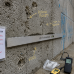
Embedment into a dry-packed or poorly consolidated joint produces pullout resistance far below the design assumption. Third, post-installation verification at a statistically meaningful sample size, not a cursory walk-through.
The ICC-ES AC38 pullout test methodology provides a field-applicable protocol for verifying anchor capacity in the installed condition. Specifying a minimum number of field pullout tests per floor level, with acceptance criteria tied to the calculated demand plus an appropriate factor, converts a paper specification into a performance verification.
This is not standard practice. It should be.
The Statement of Special Inspections required under IBC 2021 Section 1705.4 is the document where this specificity belongs. A statement that reads “periodic inspection of masonry veneer tie installation” satisfies the code requirement and communicates almost nothing about what the inspector is actually expected to verify.
A statement that identifies the required embedment depth by tie type, the maximum allowable spacing at each floor level derived from the seismic demand calculation, the mortar joint conditions that constitute a rejection criterion and the number of field pullout tests required per 500 square feet of veneer area gives the inspector an actionable standard. Writing that level of specificity into the Statement of Special Inspections requires the engineer of record to have completed the seismic demand calculation before the document is issued, which is exactly the discipline the current process lacks.
The inspection protocol and the design calculation are not separate activities. They are the same activity expressed at different project phases and treating them as independent is where the verification gap opens.
The Litigation Exposure Is Already Materializing
Post-earthquake facade investigations in the western United States over the past decade have produced a consistent finding: veneer tie failures in moderate seismic events occur on buildings that passed all required inspections and carried valid occupancy certificates. The Puget Sound case described at the outset is not an outlier.
It is a pattern.
The legal exposure for facade consultants and structural engineers who specified prescriptive tie spacing without reconciling it against ASCE 7-22 Section 13.5.3 demands is real and growing. “We followed TMS 402” is not a complete defense when ASCE 7-22 imposes a separate, more demanding requirement that the specification did not address.
Prescriptive compliance and seismic adequacy are not the same thing. The profession has known this for years and has been slow to act on it.
Expert witnesses in facade failure litigation have consistently drawn the distinction between satisfying the prescriptive masonry standard and satisfying the component-level seismic demand requirement. That distinction is now well established in the technical record, which means a defendant who relied solely on TMS 402 compliance faces a documented gap between what was done and what the standard of care required.
The argument that plan review approval constitutes validation of the seismic demand calculation has not held up in post-event investigations, because plan reviewers are not routinely checking whether ASCE 7 Chapter 13 demands were explicitly reconciled against the tie capacity at the proposed spacing. Approval confirms the submittal was received and reviewed against a checklist.
It does not confirm the seismic demand calculation was performed correctly or at all.
The practical recommendation is this: on every anchored masonry veneer project in SDC C or above, run the explicit Fp calculation per ASCE 7-22 Equation 13.3-1 at each floor level, compare the resulting demand to the capacity of the specified tie at the proposed spacing and document that reconciliation in the project record. If the prescriptive spacing satisfies the demand, you now have the calculation to prove it.
If it does not, you have caught the failure before it happens rather than after.