
- Monolithic concrete pours achieve structural continuity but do not eliminate the need for engineered sealant joints at movement locations.
- Re-entrant corners, section thickness transitions and penetration perimeters are predictable crack initiation points governed by concrete mechanics.
- Thermal expansion and drying shrinkage in a 30-foot bay can generate over 0.40 inches of total movement that undersized joints cannot accommodate.
- Sealant failures trace to mismatched ASTM C920 class ratings, missing backer rods and untested substrate carbonation rather than product quality alone.
- Effective remediation requires a movement analysis and joint pattern redesign first, not a product substitution that leaves the underlying demand unchanged.
Sealant Joints in CIP Concrete Facades: Where They Fail
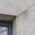
A forensic investigation of a 1990s-era civic library in the upper Midwest produced a finding that should be familiar to anyone who has spent time on concrete remediation projects: recurring diagonal cracks at re-entrant corners of monolithic cast-in-place spandrel panels, routed and sealed twice in the building’s lifetime, failing within three to five years each cycle. The structural engineer of record had specified no control joints in those bays.
The original construction documents contained no sealant joint design documentation. None.
The envelope consultant brought in for the third remediation cycle was not being asked to fix a failed sealant. She was being asked to fix a failed assumption.
That assumption is the subject of this article.
The Monolithic Myth: “No Joints” Is Not a Design Decision
Structural continuity and watertight continuity are separate performance criteria. A monolithic cast-in-place pour achieves the first.
It does not guarantee the second. This distinction is absent from most project documentation on concrete-heavy institutional work and the gap between structural logic and envelope logic is where water intrusion claims originate.
The common project team assumption runs like this: if there are no form breaks, there are no joints to detail. This conflates formwork planning with envelope engineering.
The absence of a sealant joint specification is itself a design decision and it has predictable consequences. Crack formation in CIP concrete is not random.
It follows thermal, shrinkage and restraint gradients that are calculable before the first truck arrives on site.
ACI 224R-01, Section 3.5, establishes a recommended crack width limit of 0. 010 inches for weather-exposed exterior surfaces.
That limit exists because the committee understood that cracking would occur. The question is whether the design controls where and how wide or whether the concrete decides on its own.
On the library project described above, the concrete decided. It chose re-entrant corners, thin-to-thick section transitions and window frame anchorage points.
It chose correctly, because those are the locations where mechanics dictates stress will concentrate.
The distinction between structural cracks (load-induced) and envelope cracks (movement-induced) rarely appears in project documentation. It should be a standard entry in the facade basis of design.
On institutional projects with CIP concrete facades, the basis of design document should explicitly address the expected crack width at each identified stress concentration point, the control joint spacing rationale and the sealant joint layout derived from movement calculations rather than aesthetic preference. When that documentation does not exist, the envelope consultant inherits a building that has already made its own detailing decisions.
Those decisions are recorded in the crack map, not the drawing set. Producing a crack map during condition assessment and reconciling it against the structural drawing set is the fastest way to confirm whether the original design team understood the movement demand or ignored it.
On the library project, the crack map matched the stress concentration predictions exactly. That correlation is not coincidence.
It is mechanics.
How Concrete Moves: Thermal and Shrinkage Mechanics at Facade Scale
Concrete moves more than most project teams account for during the envelope detailing phase. The coefficient of thermal expansion for normal-weight concrete runs approximately 5.5 x 10⁻⁶ per degree Fahrenheit.
Apply a 100-degree Fahrenheit seasonal temperature delta across a 30-foot bay and you get roughly 0.20 inches of reversible thermal movement. That is enough to open and close an uncontrolled crack repeatedly across a Chicago or Minneapolis service life.
Each cycle works the crack edges, degrades any sealant applied without a backer rod and proper joint geometry and pumps water into the assembly.
Drying shrinkage adds a non-reversible component that thermal calculations alone will not capture. ACI 209R-92 documents typical free shrinkage strains of 400 to 800 microstrain for normal-weight concrete, with the majority occurring in the first 90 days after placement.
A 30-foot bay undergoing 600 microstrain of free shrinkage would shorten by approximately 0.22 inches if fully unrestrained. It is never fully unrestrained.
Restraint from slab edges, embedded steel, return walls and window frame anchorage concentrates that stress at predictable locations rather than distributing it uniformly across the panel face.
ACI 209.2R-08 provides the framework for modeling long-term shrinkage and creep in hardened concrete and it should be referenced explicitly in the facade basis of design for any CIP assembly with bay dimensions exceeding 20 feet. Creep effects in tall or heavily loaded facades compound long-term movement beyond what elastic calculations predict.
Envelope detailing phases routinely ignore creep. That is a mistake on any building taller than four stories.
Cross-referencing joint sizing logic against AAMA 2400-02 thermal movement methodology is good practice even on all-concrete facades, because it forces the design team to document calculated movement before selecting sealant products. The calculation sequence matters: establish the temperature range from local climate data, apply the thermal expansion coefficient to the bay dimension, add the residual shrinkage potential based on concrete age and mix design, then sum those values to arrive at the total movement demand the joint must accommodate.
That number drives joint width selection, sealant class selection and control joint spacing. Skipping the calculation and defaulting to a standard joint width is how a specification produces a joint that is geometrically incapable of performing its function before the building reaches its fifth year of service.
On facades in climate zones with temperature swings exceeding 120 degrees Fahrenheit between seasonal extremes, which includes most of the upper Midwest and mountain West, the calculated movement values will frequently exceed the capacity of standard joint configurations. Document that finding during design development, not during the first remediation investigation.
Predictable Failure Locations: Where Cracks and Joint Failures Concentrate
Re-entrant corners fail first. The stress concentration at interior corners is well-documented in concrete mechanics literature and without a control joint or a specific reinforcement detail designed to redistribute that stress, cracking initiates there.
This is not a hypothesis. It is what the library building demonstrated twice before anyone looked at the original structural drawings and noticed the absence of corner reinforcement beyond the minimum code requirement.
A diagonal crack running at approximately 45 degrees from a re-entrant corner is the signature failure mode and it appears on CIP concrete facades across building types and climate zones with enough consistency that its absence on a condition assessment report should prompt a question about whether the inspector looked at the right locations.
Changes in section thickness create the second most common failure location. Spandrel panel to column cover transitions, reveal edges meeting flat panel faces and corbel junctions all produce differential shrinkage rates.
The thinner section loses moisture faster, shrinks faster and pulls against the thicker section. The interface cracks.
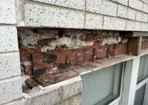
If a sealant joint does not exist at that interface by design, the crack becomes the joint and it performs accordingly. On a civic building investigated in the mid-Atlantic region, a 2-inch reveal running the full height of a CIP column cover produced a continuous crack at the reveal base within 18 months of substantial completion.
The structural drawings showed no joint at that location. The reveal was a formwork feature, not an envelope detail.
The distinction cost the owner a full-height sealant remediation on eight column bays before the building was three years old.
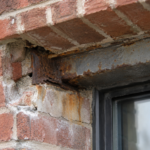
Penetration perimeters deserve more attention than they receive. Window and curtainwall anchorage points, pipe sleeves and embedded conduit interrupt the concrete matrix and create preferential crack paths.
Sealant at these locations is frequently specified as a caulk bead rather than an engineered joint. There is a meaningful difference.
An engineered joint has a calculated width, a specified depth-to-width ratio per ASTM C1193 Section 5, a backer rod and a sealant selected for the movement demand at that location. A caulk bead is a gap filled with whatever the glazing sub had on the truck.
The field result of that specification gap is a 3/16-inch bead of sealant bonded to three sides of an irregular opening, with no backer rod, no primer and no relationship to the calculated movement at that anchorage point. It fails in the first heating season.
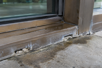
The water intrusion path it opens runs directly into the window frame anchorage pocket, where it accelerates corrosion of the embedded hardware and produces the secondary failure mode of spalling at the anchorage zone.
Horizontal-to-vertical transitions at floor lines drive cyclical movement that construction joint sealants must accommodate. The differential thermal mass between a slab edge and an exposed wall face means these two elements are rarely at the same temperature simultaneously.
The sealant at that construction joint cycles in tension and compression continuously. NIBS and ORNL survey data indicate that water intrusion at concrete facade penetrations and construction joints accounts for a disproportionate share of building envelope warranty claims on institutional projects built before 2000. The geometry of failure is consistent.
The documentation of that geometry in original construction sets is not.
Sealant Selection Failures: Modulus, Adhesion and Movement Capacity Mismatches
High-modulus sealants applied to CIP concrete joints transfer stress back into the substrate rather than accommodating movement. Two-part epoxies and certain polyurethane formulations fall into this category.
The result is cohesive failure within the sealant body or adhesive failure at the concrete interface, both of which produce water intrusion paths that look identical from the interior and require different remediation approaches. Distinguishing between the two failure modes in the field requires probing the joint during dry conditions and examining whether the sealant body has torn through its cross-section or whether the sealant has debonded cleanly from the concrete face.
Cohesive failure indicates the movement demand exceeded the sealant’s elongation capacity. Adhesive failure indicates a surface preparation or primer selection problem.
Both diagnoses point to correctable specification decisions, but they point to different corrections. Treating adhesive failure with a higher-movement-class sealant without addressing surface preparation produces the same adhesive failure on a slightly longer timeline.
Concrete surface alkalinity and carbonation state directly affect primer selection and long-term adhesion. Field-applied sealants on aged concrete without surface preparation testing are a documented failure mode.
The carbonation front on a 1990s-era facade may extend several millimeters into the surface, altering the pH environment that the primer must bond to. Skipping the surface preparation protocol because the concrete “looks clean” is how the second remediation cycle on the library building failed.
The carbonation depth on that facade measured between 4 and 7 millimeters at core sample locations, which placed the bonding surface in a pH range that the originally specified primer was not formulated to address. A phenolphthalein indicator test on freshly exposed concrete surfaces costs almost nothing and takes 10 minutes.
It was not performed on either of the first two remediation cycles. It was performed on the third.
The primer specification changed as a result and the adhesion pull-off tests that followed showed bond strengths consistent with long-term performance.
ASTM C920 classification is the specification tool for sealant movement capacity, not a marketing label. The Type, Grade, Class and Use designations define what the product can do under test conditions.
Class designations of plus or minus 12.5 percent, plus or minus 25 percent, plus or minus 35 percent and plus or minus 50 percent must be matched against the calculated joint movement, not selected by product familiarity or unit cost. Specifying a Class 25 sealant in a joint that will see 35 percent movement is a failure mode written into the specification before the building opens.
ASTM C719 testing for adhesion and cohesion of sealants under cyclic movement should be referenced alongside C920 in any remediation specification. The combination tells you both what the product is rated for and how it performs under the actual cycling conditions the facade imposes.
A product that passes C920 Class 35 testing may still show cohesive failure under the specific substrate and temperature cycling conditions of a given project if the C719 protocol is not used to verify performance under project-representative conditions. Requiring the sealant manufacturer to provide C719 test data for the specified substrate type and temperature range is a reasonable specification requirement that most manufacturers can satisfy from existing test records.
Silicone versus polyurethane selection on concrete facades involves tradeoffs worth naming directly. Silicone accommodates higher movement, resists UV degradation and maintains flexibility at low temperatures.
Polyurethane accepts paint and shows less dirt pickup on textured concrete surfaces. Neither category performs adequately without proper joint geometry and substrate preparation.
On exposed architectural concrete where surface appearance is a design requirement, the dirt pickup behavior of silicone sealants at joint edges is a legitimate concern that has driven specifiers toward polyurethane products in locations where the movement demand is within polyurethane’s rated capacity. Where movement demands exceed that capacity, the appearance tradeoff must be accepted or the joint pattern must be redesigned to reduce movement at individual joint locations.
Joint Geometry: The Specification Gap Between Design and Field
ASTM C1193 Section 5 establishes width-to-depth ratio requirements for sealant joints and those requirements exist because sealant mechanics depend on geometry, not just product selection. A joint that is too deep relative to its width fails in tension at lower movement than the product rating suggests, because the sealant cannot develop the hourglass deformation profile that distributes strain across the full cross-section.
The standard calls for a width-to-depth ratio of 2:1 for joints up to 1/2 inch wide, with a minimum depth of 1/4 inch. These are not conservative guidelines.
They are the geometric conditions under which the product ratings were established. Deviating from them in the field invalidates the performance assumptions built into the specification.
The field condition on most CIP concrete facades is a routed crack or a saw-cut joint with no backer rod installed. The sealant bonds to three sides.
Three-sided adhesion prevents the joint from functioning as designed and produces failure at movement levels well below the product’s rated capacity. This is not a controversial finding.
It is the first thing covered in any sealant manufacturer’s technical documentation and the last thing verified during field quality control. On a remediation project for a 1980s-era university science building, field observation during sealant installation found that the waterproofing subcontractor had omitted backer rod installation on approximately 60 percent of the routed joints in the first two days of work.
The joints had been routed to a depth of 3/4 inch and a width of 3/8 inch. Without backer rod, the sealant was being applied at full joint depth, producing a depth-to-width ratio of 2:1 in the wrong direction.
The quality control protocol required a depth gauge check at every joint before sealant application. That protocol had not been communicated to the field crew.
Catching that condition on day two rather than at the end of the project required a resident observer who understood joint geometry requirements, not just sealant product handling.
Minimum joint width for CIP concrete facades should be calculated, not assumed. A 3/8-inch joint is a common default.
On a 30-foot bay with the thermal and shrinkage movement values discussed above, that joint needs to accommodate up to 0.40 inches of total movement across its service life. At plus or minus 25 percent movement capacity, a 3/8-inch joint handles plus or minus 0.094 inches.
The math does not work. The joint needs to be wider, the sealant needs a higher movement class rating or the bay needs a control joint that reduces the movement demand at each individual joint location.
Those are the three options. Picking none of them is how buildings end up in their third remediation cycle.
Documenting the calculation in the specification section, not just in the basis of design, gives the field team and the quality control observer a reference point for verifying that the installed joint dimensions match the design intent. A specification that states “minimum 3/8-inch joint width” without showing the calculation that produced that dimension gives the contractor no basis for questioning a narrower condition encountered in the field.
The calculation belongs in the specification.
Remediation Logic: Fixing the System, Not the Symptom
Routing and sealing an active crack in CIP concrete without addressing the movement demand that created it produces a predictable result. The sealant fails.
The timeline varies between two and seven years depending on climate zone, joint geometry and product selection, but the outcome does not vary. This is the lesson the library building taught twice before the third consultant changed the approach.
Effective remediation of CIP concrete facades begins with a movement analysis, not a product selection. Calculate the thermal movement for the bay dimensions and the local temperature range.
Add the remaining shrinkage potential for the concrete age. Identify the restraint conditions that concentrate stress at specific locations.
Then design a joint pattern that distributes that movement across a sufficient number of joints to keep individual joint movement within the capacity of an achievable sealant specification. On the library building, the third remediation cycle added saw-cut control joints at the midpoint of each spandrel bay, reducing the effective bay dimension from 28 feet to 14 feet and cutting the thermal movement demand at each joint location by approximately half.
That single change brought the movement demand within the capacity of a standard Class 35 silicone sealant in a properly sized joint. The two previous remediation cycles had specified Class 25 polyurethane in a 3/8-inch routed crack with no backer rod.
The movement demand had not changed between cycles. Only the product changed and the product was never the problem.
On existing facades where cutting new control joints is structurally constrained, the remediation strategy shifts toward higher-movement-capacity sealants in properly prepared joints with correct geometry. That means removing all existing sealant, evaluating the substrate for delamination and carbonation, applying the specified primer system and installing a backer rod before any sealant touches the joint.
It also means specifying ASTM C920 Class 50 material in joints where movement demands exceed what lower-rated products can handle and documenting that decision in the project record. Substrate evaluation should include delamination sounding across the full joint length, not just at visible spall locations, because delaminated concrete behind an intact surface will not provide adequate bond for any sealant system regardless of product selection or primer application.
Identifying delamination before sealant installation avoids the scenario where a newly applied sealant system pulls the substrate face off the wall during the first thermal cycle, which is a failure mode that generates significant owner frustration and legitimate questions about the quality of the condition assessment that preceded the remediation.
What the Next Generation of CIP Facades Gets Wrong
New institutional and civic construction is returning to exposed cast-in-place concrete as an aesthetic and structural choice. The detailing assumptions from the 1970s and 1990s are returning with it.
Envelope consultants brought in during design development on these projects consistently find the same condition: a structural drawing set with no sealant joint layout, a specification section referencing ASTM C920 without Type, Grade, Class or Use designations and a project team that treats the concrete facade as a structural system that happens to face the weather.
The water control layer in a CIP concrete assembly is not the concrete itself. Concrete is permeable.
The water control layer is the combination of properly designed and installed sealant joints at all movement locations, correctly detailed penetration seals and a surface treatment strategy that accounts for the concrete’s long-term permeability. All four control layers require explicit design attention on CIP facades.
The thermal layer requires continuous insulation detailing that does not compromise the water control layer. The air control layer requires that every penetration through the concrete be treated as an air leakage path until sealed and tested.
On a recently completed civic center project reviewed during design development, the envelope consultant found that the mechanical engineer had located 14 pipe sleeve penetrations through the CIP facade in locations where the structural engineer had placed primary reinforcing at 6-inch spacing. The sleeve diameters required cutting reinforcing to install.
The resulting concrete section at each penetration was significantly weakened and the stress concentration around each sleeve created a high-probability crack initiation point that no one had identified because the structural and envelope drawing sets had not been coordinated. Catching that condition during design development cost two coordination meetings.
Catching it after construction would have cost a penetration-by-penetration remediation across all 14 locations.
The envelope consultant who waits until the third remediation cycle to ask for the original sealant joint documentation is asking the right question five years too late. Ask it during design development.
If the answer is that no such documentation exists, write it yourself or make it a condition of your engagement. The concrete will move.
The only question is whether the joints were designed to accommodate that movement or whether the cracks were.