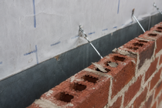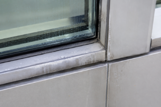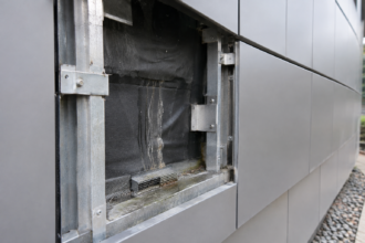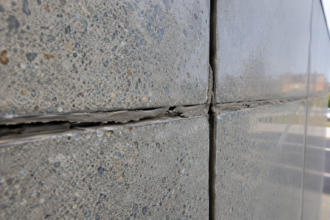
- Polycarbonate expands 6 to 8 times faster than glass, making standard glazing edge clearances catastrophically insufficient for commercial panel installations.
- UV cap layer thickness must be specified in microns because generic UV-stabilized language accepts panels with service lives under seven years.
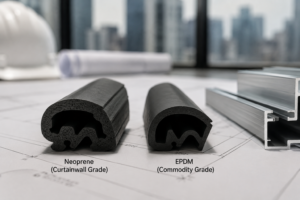
- Neoprene gaskets designed for glass cannot handle differential movement at aluminum framing interfaces and EPDM is the minimum standard for polycarbonate.
- Multiwall panel cells are open at the ends and require specific top and bottom closure treatments that sealed glass specifications never address.
- Projects specified between 2010 and 2018 are now revealing whether material-specific details were used or glass sections were simply adapted.
Multiwall Polycarbonate Panels: Where Facade Specs Fail
A curtainwall contractor on a mid-rise institutional project in the upper Midwest discovered, during a routine 7-year inspection, that the neoprene gaskets at every aluminum framing interface along the south-facing clerestory had compressed beyond recovery. The polycarbonate panels were racking laterally under wind load.
Several cells showed internal condensation from moisture infiltration through the failed seals. The specification had been adapted directly from the project’s vision glass section with no modification for polycarbonate movement rates.
Nobody flagged the discrepancy during design review. That failure was entirely predictable and entirely preventable.
Why Polycarbonate Is Appearing in Commercial Facade Specifications
Three converging pressures are pushing multiwall polycarbonate into mid-rise commercial and institutional work: daylighting performance targets that don’t require vision-quality transparency, cost pressure relative to structural glass assemblies and weight reduction requirements in retrofit and addition projects where existing structure limits dead load.
Common applications include clerestories, spandrel zones, canopy soffits and translucent wall panels. In each of these applications, specifiers are frequently borrowing from the project’s vision glass section and making minimal adjustments.
That shortcut fails because polycarbonate is not a glass substitute. It is a thermoplastic with fundamentally different movement, degradation and attachment behavior.
Multiwall configurations dominate commercial work because of their thermal performance. Panels are available in thicknesses from 10mm to 40mm with effective R-values ranging from approximately R-1.5 to R-3.
5 depending on cell configuration. That performance range drives substitution decisions.
It is rarely paired, in the same specification section, with the corresponding movement data and attachment requirements the material actually demands. Single-skin and twin-wall configurations appear in signage and agricultural applications; for commercial facade work, triple-wall and five-wall panels are the standard choice.
The weight differential is a legitimate structural argument that often initiates the substitution. Multiwall polycarbonate panels in the 25mm to 40mm range typically weigh 3 to 5 kg/m², compared to 25 to 30 kg/m² for an insulating glass unit of equivalent thermal performance.
On an addition project where the existing concrete frame is already at or near its calculated dead load capacity, that difference can determine whether the addition is feasible without structural reinforcement. The problem is that the weight argument gets made during schematic design, the material gets locked in and the specification writer who eventually produces the facade section may have no direct knowledge of why polycarbonate was selected or what the manufacturer’s installation requirements actually are.
The substitution rationale and the technical requirements travel separately through the project delivery process and they frequently never meet.
IBC Section 2606 governs light-transmitting plastic panels in commercial construction and imposes area and height limitations based on occupancy and fire separation distance that do not apply to glass. A specification that copies the glass section without addressing IBC 2606 compliance has not just missed a technical requirement; it has missed a code requirement that can trigger plan review rejection or, worse, a post-occupancy correction notice.
Thermal Expansion Rates: The Number Specifiers Are Not Using
Polycarbonate has a coefficient of linear thermal expansion (CLTE) of approximately 0.065 to 0. 068 mm/mm/°C per ASTM E831 and ISO 11359. That is roughly 7 to 8 times the CLTE of aluminum and approximately 6 times that of glass.
This single number is the root cause of most polycarbonate facade failures and it is absent from the majority of adapted specifications I review.
Run the practical calculation. A 4-meter panel in a dark-framed south-facing application in IECC Climate Zone 5 or 6 will experience a service temperature delta of 70°C or more.
The resulting thermal movement is approximately 18 to 19mm across the panel length. Most aluminum glazing systems are detailed for 3 to 4mm total edge clearance, which is appropriate for glass.
It is catastrophically insufficient for polycarbonate. Manufacturer guidelines for multiwall polycarbonate consistently require 3 to 5mm of clearance per meter of panel length.
On a 4-meter panel, that means 12 to 20mm of designed clearance at the panel edges. No glass spec provides that.
The consequences of under-designed expansion joints are not subtle. Panel buckling is visible.
Gasket extrusion is visible. Frame distortion, if it progresses far enough, compromises the water control layer at every affected joint in the assembly.
Color selection compounds the movement problem in ways that specifications almost never address. Dark-colored or bronze-tinted panels absorb significantly more solar radiation than clear or opal panels, driving surface temperatures well above ambient air temperature.
A clear panel on a south-facing facade in Climate Zone 5 might reach 60°C on a peak summer day. The same facade with a dark bronze tint can reach 80°C or higher under the same conditions.
That 20°C difference translates directly into additional thermal movement that the framing system must accommodate. Specifiers who select panel color for aesthetic reasons without recalculating the movement envelope for that color’s solar absorptance are designing in a failure mode before the first panel is installed.
Manufacturer technical data sheets publish solar absorptance values by color; those values belong in the movement calculation, not just the energy model.
One additional point that specifiers frequently miss: ASTM E1300, the standard load resistance calculation method for glass, does not apply to polycarbonate. Specifiers defaulting to E1300 for structural adequacy are using an inapplicable reference.
Polycarbonate panel structural performance must be evaluated against manufacturer load tables and, where project conditions require independent verification, ASTM D638 tensile property data. These are not interchangeable documents.
In high-wind-exposure categories, ASCE 7-22 Component and Cladding pressure calculations should be run against manufacturer-published deflection limits for the specific panel thickness and span, not against glass deflection criteria. The allowable deflection limits for polycarbonate under lateral load are different from glass and the failure mode is different.
Glass fractures. Polycarbonate deflects and, if the framing system cannot accommodate that deflection, transfers load into the gasket and seal system in ways that accelerate the compression set failures described in the next section.
UV Degradation Timelines and the Co-Extrusion Protection Layer
Unprotected polycarbonate yellows and becomes brittle within 2 to 5 years of exterior exposure. Co-extruded UV-stabilized cap layers are the industry-standard mitigation and they work.
The problem is that cap layer thickness varies widely and specifications rarely define a minimum.
Commercial-grade panels carry 50 to 175 microns of UV-stabilized co-extrusion on the weather-exposed face. Panels at the lower end of that range, which includes a significant portion of lower-cost import product, reach end of optical performance within 5 to 7 years.
A specifier who writes “UV-stabilized polycarbonate” without defining cap layer thickness has written a specification that accepts panels with a service life shorter than the building’s first major maintenance cycle.
Degradation is not uniform across orientations. South and west exposures in ASHRAE Climate Zones 2 and 3 show measurably accelerated yellowing compared to north-facing applications.
A blanket 10-year warranty on a panel installed on a south-facing clerestory in Phoenix is not the same protection as the same warranty on a north-facing soffit in Minneapolis. Specify exposure-specific warranty language.
If a manufacturer won’t provide it, that tells you something about their confidence in the product’s performance on your specific facade.
What degradation looks like in service: new multiwall panels typically transmit 82 to 88% of visible light. A degraded panel may drop to 60 to 65% transmission, which undermines the daylighting performance that justified the material selection in the first place.
Surface crazing accompanies the transmission loss and increases impact failure risk.
The applicable weathering test standards are ASTM G154 (UV fluorescent lamp exposure) and ASTM G155 (xenon arc exposure). Require minimum 4,000-hour test results with no more than 5 delta-E color shift and less than 10% light transmission loss as a baseline submittal requirement.
Make that a hard requirement in the submittal schedule, not a post-award request.
One field observation worth adding to any pre-specification conversation with a manufacturer: ask specifically whether the UV cap layer is applied to one face or both. Some multiwall panels are manufactured with UV protection only on the designated weather-exposed face.
If the panel is installed with the protected face oriented incorrectly, which happens when installation instructions are not translated into explicit shop drawing requirements, the unprotected face receives full UV exposure and the degradation timeline collapses to the 2 to 5 year range for unprotected material. That is not a hypothetical.
It is a documented installation error on projects where the specification said “UV-stabilized” but did not define which face carries the cap layer or require that the protected face be permanently marked before delivery. Require factory-applied directional marking on every panel as a submittal and delivery requirement.
That single line in the specification eliminates an entire category of installation error.
Gasket and Seal Compression Failures at Aluminum Framing Interfaces
The differential movement problem at framing interfaces is where the thermal expansion numbers become a field failure. Aluminum expands at approximately 0.023 mm/mm/°C.
Polycarbonate expands at 0.065 to 0. 068 mm/mm/°C.
On a 3-meter panel over a 70°C service temperature delta, the differential movement at a typical framing interface can exceed 10mm. Standard neoprene glazing gaskets, which are specified for glass assemblies, have a compression recovery range that does not accommodate that magnitude of differential movement.
EPDM outperforms neoprene for long-term compression set resistance in polycarbonate applications. Silicone gaskets offer superior UV and temperature resistance but require compatibility verification with polycarbonate surface chemistry.
Some silicone formulations cause stress crazing at the panel edge, which initiates cracking that propagates inward under subsequent thermal cycling. That is not a theoretical risk; it is a documented failure mode.
The failure sequence is predictable: initial gasket compression under installation torque, thermal cycling fatigue over the first two to three heating seasons, compression set, gap formation at the framing interface, water infiltration, internal cell condensation and finally structural degradation of the panel-to-frame connection. By the time condensation is visible inside the cells, the water control layer has already failed at multiple points in the assembly.
The design mitigation is floating-point or sliding-clip attachment systems that allow panel movement independent of gasket compression. These systems are standard in manufacturer-engineered polycarbonate framing.
They are absent from adapted glass specifications because glass doesn’t need them. Per ASTM C864, which covers dense elastomeric compression seals, specify minimum compression set resistance of 25% or less after 22 hours at 70°C per ASTM D395 Method B as a gasket qualification requirement at polycarbonate framing interfaces.
That single submittal requirement will eliminate most of the problematic gasket products before they reach the job site.
Installation torque is a related variable that specifications almost never address for polycarbonate applications. Glazing contractors installing polycarbonate into aluminum framing systems are accustomed to glass, which does not deflect under fastener torque.
Polycarbonate does. Over-torqued fasteners at fixed-point attachments create stress concentrations at the fastener hole that become crack initiation sites under thermal cycling.
Manufacturer installation guidelines specify maximum torque values for each fastener type and panel thickness, typically in the range of 2 to 4 N·m for self-tapping screws into 25mm panels. Those values belong in the specification’s execution section, not just in the manufacturer’s literature that the installer may or may not read.
Including fastener torque requirements in the specification and making them a quality control inspection item during installation, directly reduces the incidence of fastener-initiated cracking that presents as unexplained panel fracture two to four years after installation.
Condensation Control and Thermal Bridging in Multiwall Cell Systems
Multiwall polycarbonate panels are not hermetically sealed like insulating glass units. The internal cells are open at the panel ends and must be actively managed.
This distinction matters enormously for the vapor control layer in the assembly.
The standard practice is to seal the bottom edge of each panel with a solid aluminum tape or purpose-made end closure and leave the top edge open with a breathable tape that allows moisture vapor to escape while blocking liquid water and insects. Reverse that configuration and you trap condensation inside the cells permanently.
I have opened panels from failed assemblies where the interior cells were packed with biological growth because the installer used solid tape at both ends, following standard glass glazing practice and sealed in whatever moisture was present at installation.
Thermal bridging at the aluminum framing members is a separate issue that specifications frequently treat inadequately. The aluminum extrusions that support polycarbonate panels in curtainwall configurations are continuous thermal bridges through the thermal control layer.
In IECC Climate Zones 5 through 7, unbroken aluminum framing can reduce the effective R-value of a nominal R-3.5 multiwall panel assembly to R-1. 5 or lower at framing lines.
Continuous insulation at the framing perimeter or thermally broken framing extrusions, is not optional in these climate zones if the assembly is expected to meet ASHRAE 90.1-2022 envelope performance requirements for opaque and semi-transparent assemblies.
The end closure material selection also affects long-term cell performance in ways that the specification should address explicitly. Aluminum tape closures are dimensionally stable and provide a positive moisture barrier, but they do not accommodate the panel’s thermal movement at the end condition.
Over multiple heating and cooling cycles, a rigidly adhered aluminum tape closure can delaminate at the panel edge as the polycarbonate moves relative to the tape’s adhesive bond. Purpose-made end closure profiles in flexible PVC or EPDM, which are available from panel manufacturers and sized to specific panel thicknesses, maintain the seal through the movement range that aluminum tape cannot.
Specifying “aluminum tape end closure” without addressing movement compatibility is a detail that works at installation and fails within three to five years in high-movement applications. Require manufacturer-supplied end closure profiles as a specified product, not a contractor-selected accessory and include them in the submittal schedule alongside the panel product data.
Condensation management also requires attention to panel slope. Multiwall panels installed at slopes below 5 degrees from horizontal trap any condensation that forms inside the cells at the low end, where it pools against the solid bottom closure.
Panels at or above 5 degrees drain by gravity toward the bottom closure, which should include a small weep gap or perforated section to allow accumulated moisture to exit. That detail is standard in manufacturer installation guides and absent from most adapted specifications.
On horizontal or near-horizontal canopy applications, the condensation management strategy requires a different approach entirely, typically involving vented end closures at both edges with a slope-to-drain condition built into the framing and that condition should be called out explicitly in the specification rather than left to the installer’s judgment.
Specification Language That Actually Protects the Project
Adapted glass specifications fail polycarbonate applications because they address the wrong set of risks. The specification language that protects the project addresses five specific items that glass specs never touch.
First: define minimum cap layer thickness in microns, not by brand or by a generic “UV-stabilized” descriptor. Second: require ASTM G154 or ASTM G155 weathering test results at 4,000 hours minimum as a submittal item, with defined pass/fail thresholds for color shift and light transmission.
Third: specify edge clearance as a function of panel length, not as a fixed dimension; 3 to 5mm per meter is the defensible range for most commercial applications. Fourth: require gasket qualification per ASTM D395 Method B compression set testing, with EPDM as the minimum material standard at polycarbonate framing interfaces.
Fifth: specify end closure treatment explicitly, identifying which edge receives solid closure and which receives breathable tape and make that a shop drawing review item.
None of these requirements are exotic. Every reputable multiwall polycarbonate manufacturer publishes installation guidelines that address all five.
The specification gap exists because specifiers are not reading those guidelines before writing the section.
A practical addition to the five items above: require a pre-installation conference that includes the panel manufacturer’s technical representative, the glazing contractor’s foreman and the project’s special inspector if one is assigned to the envelope scope. That conference should cover thermal movement calculations for the specific panel dimensions and climate, fastener torque requirements, end closure installation sequence and the quality control checkpoints for edge clearance verification before framing is closed.
Pre-installation conferences are standard practice for complex glazing assemblies and are called for in most curtainwall specifications. They are rarely included in polycarbonate panel sections adapted from glass specs, because glass specs assume a glazing contractor who already knows the material.
Polycarbonate is still unfamiliar enough to most glazing crews that the pre-installation conference is not a formality; it is a direct risk reduction measure. Including it as a specified requirement, with a written agenda submitted to the architect for review, creates a documented record that the installation team received material-specific guidance before work began.
That documentation matters when a warranty claim arrives five years later.
What the Next Decade of Polycarbonate Facades Will Reveal
The projects specified between 2010 and 2018, when polycarbonate began appearing regularly in commercial facade work, are now entering their second decade of service. The inspection findings from that cohort will define whether the industry corrects its specification practices or continues adapting glass sections and absorbing the warranty claims.
The assemblies that will perform are the ones where someone read the manufacturer’s technical data sheet before writing the specification, calculated the actual thermal movement for the specific panel dimensions and climate and selected framing hardware that accommodates differential movement rather than resisting it. That is not complex engineering.
It requires applying material-specific data to material-specific details. The assemblies that will fail are the ones where polycarbonate was treated as a lighter, cheaper version of glass.
It is not. It moves differently, it degrades differently and it requires a different set of control layer decisions at every framing interface in the assembly.
The sooner that distinction is built into standard office specification templates, the fewer clerestories we will be opening up at year seven.