- A building in Climate Zone 6 ran 28% over projected utility costs because thermal bridges were never modeled or mitigated.
- Steel studs alone can reduce nominal R-19 cavity insulation to an effective R-7 or R-8 at the assembly level.
- Stainless steel cladding anchors through continuous insulation can reduce local effective R-value by 20 to 35 percent per bracket.
- ASHRAE 90.1-2022 and NECB 2020 are tightening requirements in ways that make unbroken metal attachment systems increasingly non-compliant.
- Mid-construction thermography costs thousands of dollars and can prevent corrections that cost hundreds of thousands after occupancy.
Thermal Bridging in Commercial Envelopes: The Performance Gap Your Energy Model Isn’t Capturing
A building owner in the upper Midwest commissions a full energy model demonstrating compliance with ASHRAE 90.1-2019. The model checks out.
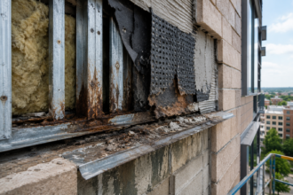
Construction documents show continuous insulation at the correct R-value for Climate Zone 6. Eighteen months after occupancy, utility bills run 28% above projections. An infrared thermography scan during the first heating season reveals a systematic network of steel shelf angles, stainless cladding anchors and bare concrete slab edges conducting heat directly through the facade in a pattern so consistent it looks intentional.
The insulation was installed exactly as specified. The thermal bridges were simply never modeled, never detailed and never mitigated.
That gap between nominal compliance and actual performance is the subject of this article.
What Thermal Bridging Actually Is: and Why It’s Hiding in Plain Sight
Thermal bridging occurs whenever a material of higher conductivity creates a preferential conductive pathway through or around the thermal control layer. In commercial construction, the three categories worth distinguishing are conductive bridges (steel studs, shelf angles, concrete balcony slabs penetrating the plane of insulation), geometric bridges (corners, parapets and reveals where surface area changes relative to volume) and convective bridges (gaps and voids in insulation that allow air circulation within the assembly).
Repeating thermal bridges follow a predictable pattern tied to framing geometry: stud spacing, girt spacing, anchor spacing. Non-repeating bridges are discrete events: a structural connection, a pipe penetration, a column passing through the envelope.
Both categories demand separate treatment in calculation and in detailing. The distinction matters practically because repeating bridges are addressed through assembly-level correction factors applied uniformly across a wall area, while non-repeating bridges require individual calculation of point or linear transmittance values that are then added to the clear-field assembly U-factor.
Treating a shelf angle as a repeating bridge when it occurs only at floor lines or ignoring a structural column penetration because it appears infrequently, produces systematic underestimates of heat flow that compound across the full facade area.
The quantitative language for this is linear transmittance, expressed as a Psi-value in W/(m·K) and point transmittance, expressed as a chi-value in W/K. ISO 10211 establishes the numerical simulation methodology for calculating both.
ASHRAE Handbook of Fundamentals Chapter 27 addresses the parallel path and isothermal planes methods for framed assemblies, which are simpler to apply but consistently overstate effective R-value when bridge density is high. The isothermal planes method, in particular, assumes that heat flow is one-dimensional and perpendicular to the wall plane.
That assumption breaks down at every structural connection, every corner and every location where the bridge geometry changes direction. Designers who rely on isothermal planes calculations at complex junctions are producing numbers that look defensible in a submittal but do not reflect actual heat flow.
Visual inspection finds nothing. A correctly installed assembly with catastrophic thermal bridging looks identical to a well-performing one.
Only calculation or thermography reveals what’s actually happening at the thermal control layer. This is the fundamental reason thermal bridges persist in commercial construction at a scale that would be unacceptable if the problem were visible.
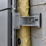
A missing section of insulation is obvious during construction inspection. A stainless steel anchor bracket passing through four inches of continuous polyisocyanurate is invisible once the cladding goes on and its thermal impact never appears on any inspection checklist.
The Real Performance Penalty: How Much Insulation Value Are You Actually Losing?
The steel stud penalty is the most documented example in North American practice and it still surprises people when they see the numbers. A nominal R-19 batt installed in a 3.5-inch steel stud cavity delivers an effective R-value of approximately R-7 to R-8 at the assembly level.
Oak Ridge National Laboratory research has quantified this repeatedly: steel framing reduces clear-field insulation performance by 40 to 60 percent depending on stud gauge, spacing and flange width. ASHRAE 90.1-2019 Table A2.
3 provides assembly correction factors for steel-framed walls precisely because nominal cavity insulation values are operationally meaningless without them.
The mechanism behind this penalty is straightforward but frequently underappreciated in practice. Steel has a thermal conductivity of approximately 50 W/(m·K).
Mineral wool batt insulation sits around 0.04 W/(m·K). That ratio of roughly 1,250 to 1 means that even a stud flange occupying a small fraction of the wall cross-section dominates the heat flow path through the assembly.
At 16-inch stud spacing with 3-5/8-inch 20-gauge studs, the framing fraction is approximately 15 percent of the wall area. That 15 percent fraction carries a disproportionate share of the total heat flow, which is why the effective R-value drops so far below the nominal cavity value.
Increasing batt thickness in the cavity without adding continuous insulation on the exterior does almost nothing to improve effective thermal resistance, because the limiting factor is the stud, not the insulation depth.
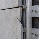
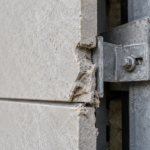
Cladding anchors compound the problem in assemblies that use continuous insulation to compensate for the stud penalty. A single stainless steel bracket, 8mm diameter, passing through 4 inches of continuous polyisocyanurate creates a point thermal bridge that reduces local effective R-value by 20 to 35 percent depending on bracket spacing and geometry.
At typical anchor spacing for heavy cladding systems (300 to 400mm on center horizontally), the cumulative impact across a facade is substantial. Switching from stainless to thermally broken aluminum or fiberglass-reinforced polymer brackets reduces conductivity by an order of magnitude.
That’s not a preference; it’s the only defensible approach when continuous insulation thickness is the primary strategy for code compliance. Stainless steel has a thermal conductivity of approximately 15 W/(m·K).
Fiberglass-reinforced polymer brackets typically fall between 0.3 and 0. 5 W/(m·K).
The physics of that substitution are not subtle and the cost premium for thermally broken brackets on a typical mid-rise commercial project is recoverable within the first few years of operation in Climate Zones 5 and above.
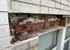
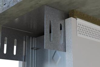
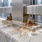
Shelf angles in brick veneer and precast panel systems create linear bridges that are frequently the worst performers in the assembly. A steel shelf angle bearing on a concrete slab, with no thermal break at the interface and no continuous insulation wrapping the angle, can reduce effective R-value in the spandrel zone by 50 percent or more within 300mm of the connection.
The geometry concentrates the problem: the angle is typically a 5-inch or 6-inch leg bearing on the slab, the slab itself is already a thermal bridge and the two elements in direct contact create a compounding effect that no amount of cavity insulation above or below the floor line can compensate for. The effective R-value is the only metric that matters for energy modeling.
Nominal values are a starting point for material selection, not a basis for compliance.
Code Pressure Is Mounting: What ASHRAE 90.1 and NECB Now Require
ASHRAE 90.1-2019 Section 5. 5.
3. 1 defines continuous insulation explicitly as insulation that is continuous across all structural members without thermal bridges other than fasteners and service openings.
The definition exists because the code writers understood that cavity insulation in steel-framed assemblies cannot meet minimum effective thermal resistance requirements without supplemental ci. The ci requirements in 90.1-2019 are prescriptive minimums; they do not account for the thermal bridges introduced by the cladding attachment system that holds the cladding over that ci.
A project that specifies R-15 ci in Climate Zone 6 and then installs a stainless steel bracket grid at 300mm spacing has not met the intent of Section 5.5.3.1, regardless of what the plan review stamp says.
The 2020 National Energy Code of Canada for Buildings shifts further toward whole-assembly effective thermal resistance, requiring that calculations account for repeating thermal bridges in the compliance pathway. NECB 2020 Part 3 effective thermal resistance tables are explicit about this.
Canadian practice has generally been ahead of U. S.
practice on this point for a decade. Part of the reason is that the NECB has historically been more prescriptive about assembly-level performance rather than component-level specification, which forces designers to account for what the assembly actually delivers rather than what its individual components are rated at.
Several Canadian provinces, including British Columbia under its Step Code program, have pushed even further by requiring that thermal bridge calculations be submitted as part of the energy compliance documentation, not simply assumed away through reference to standard assembly tables.
The 2021 IECC tightens ci minimums in Climate Zones 4 through 8 and has been adopted with varying amendments across jurisdictions. ASHRAE 90.1-2022 goes further still, with additional ci requirements in those same climate zones that will force a genuine rethinking of cladding attachment strategy on many project types.
In Climate Zone 7, for example, the 90.1-2022 prescriptive ci requirement for mass walls increases in a way that makes unbroken metal attachment systems functionally incompatible with compliance unless the designer can demonstrate through whole-assembly calculation that the effective thermal resistance still meets the threshold. That calculation requirement is not yet uniformly enforced, but the trajectory of the code is clear.
The enforcement gap is real and persistent. Plan reviewers check whether ci is specified.
They rarely verify that the thermal bridges introduced by shelf angles, structural connections and cladding anchors have been calculated or mitigated. Specifying ci and detailing it as if thermal bridges don’t exist is a compliance strategy that satisfies the letter of the code while violating its intent.
Until jurisdictions require submission of thermal bridge calculations as a standard part of the envelope compliance package, the gap between what the code requires and what gets built will remain wider than the industry acknowledges.
The Highest-Risk Locations in a Commercial Envelope: Where to Look First
Five locations account for the majority of thermal bridge severity in commercial construction and they warrant attention in roughly this order of magnitude.
Slab edges in concrete frame buildings are among the most severe non-repeating bridges in practice. A 200mm concrete slab bearing on an exterior column line, with no thermal break at the slab-to-exterior interface, creates a linear transmittance that Building Science Corporation research has quantified as responsible for significant heating load contributions in Climate Zones 5 and above.
These details are routinely absent from design documents until an envelope consultant raises them during design review. Concrete has a thermal conductivity of approximately 1.7 W/(m·K) and a full-depth slab extending to the exterior face of the building creates a direct conductive pathway that bypasses the entire wall assembly.
On a ten-story concrete frame building in Climate Zone 6, unbroken slab edges at every floor line can account for 15 to 20 percent of the total envelope heat loss, a contribution that never appears in the energy model because the model treats the wall assembly as uniform between floor lines. Prefabricated structural thermal break elements designed for this application, products from manufacturers including Schock and Halfen, have been in use in European practice for two decades and are increasingly specified in North American high-performance projects.
The structural engineering coordination required to incorporate them is real but manageable when the conversation happens during schematic design rather than during construction document production.
Shelf angles and relieving angles at floor lines in brick veneer and panel systems are the second priority. The geometry concentrates heat flow at the slab edge while the angle itself conducts across the insulation plane.
A thermally broken shelf angle assembly with continuous insulation carried behind and below the angle is the minimum acceptable approach in Climate Zones 5 through 8. Thermally broken shelf angle systems use a structural thermal break pad between the angle and the slab bearing surface, combined with a redesigned insulation detail that maintains the ci layer through the spandrel zone without interruption. The coordination challenge is that the structural engineer typically sizes the shelf angle for gravity load, the architect details the insulation and the cladding contractor installs the bracket system and none of these parties has historically been responsible for the thermal performance of the combined assembly.
Assigning that responsibility explicitly in the project specifications and requiring thermal bridge calculations for shelf angle conditions as a submittal item, is the only reliable way to close that coordination gap.
Cladding attachment systems rank third because their impact scales with facade area. Bracket spacing, bracket material and bracket depth through the insulation plane all affect the magnitude of the bridge.
ASHRAE 90.1 Normative Appendix A provides reference assembly U-factors, but those values do not include the contribution of cladding attachment hardware. A designer who uses the Appendix A U-factor for a ci wall assembly without adding the thermal bridge contribution of the anchor system is producing a compliance calculation that understates actual heat flow.
The magnitude of that understatement depends on anchor density and material, but on a heavy cladding system with stainless anchors at 300mm spacing, the error can exceed 30 percent of the assembly U-factor. That error propagates directly into the energy model and directly into the gap between projected and actual utility costs.
Parapet and roof-wall intersections are a dual liability: thermal bridging and condensation risk converge at the same location. A steel stud parapet with no thermal break at the top of the wall assembly, combined with a roof membrane that terminates without continuous insulation wrapping the parapet, creates conditions for both energy loss and chronic moisture accumulation.
Parapets deserve their own detail sheet on every project. The thermal bridge at the parapet is a three-dimensional problem: heat flows laterally through the stud framing, vertically through the top plate and upward through the parapet cap.
Two-dimensional analysis of any single cross-section understates the total heat flow. Field observations on projects where parapet details were corrected mid-construction consistently show that the corrected detail, with ci wrapping the full parapet height and a thermally broken cap connection, reduces measured surface temperatures on the interior parapet face by 4 to 6 degrees Celsius under design winter conditions.
That temperature difference is the margin between a surface that stays above the dew point and one that accumulates condensation seasonally.
Fenestration perimeters, particularly in curtain wall systems, complete the list. The aluminum framing members that define curtain wall grid lines are thermal bridges by definition.
Thermally broken framing reduces but does not eliminate the bridge. The interface between the curtain wall system and the opaque wall assembly is frequently the worst-performing linear detail in the entire envelope.
At this transition, the curtain wall mullion terminates against the backup wall, the ci layer must be interrupted to accommodate the structural connection and the air barrier transition between the two systems introduces additional complexity. NFRC 100 governs the thermal performance rating of fenestration products, but that rating applies to the center-of-glass and frame conditions within the product boundary.
The linear thermal bridge at the perimeter of the curtain wall unit, where it meets the opaque wall, is outside the NFRC product boundary and is the designer’s responsibility to calculate and address. On projects where this detail has been analyzed, the perimeter linear transmittance can add 10 to 20 percent to the effective U-factor of the curtain wall zone when integrated over the full spandrel and jamb condition.
Calculation Methods: What the Models Are and Aren’t Telling You
Two-dimensional finite element analysis following ISO 10211 is the only method that accurately captures linear thermal transmittance at complex junctions. For repeating bridges in framed assemblies, the parallel path method in ASHRAE Handbook of Fundamentals Chapter 27 provides a reasonable approximation when stud spacing is uniform and the bridge geometry is simple.
It fails at corners, at structural connections and anywhere the bridge geometry changes in the third dimension. Software tools including THERM, developed by Lawrence Berkeley National Laboratory and available at no cost, implement the two-dimensional finite element method and are accessible to practitioners without specialized thermal simulation backgrounds.
THERM has been validated against ISO 10211 test cases and produces Psi-values and chi-values that can be directly incorporated into whole-building energy models. The learning curve for basic junction analysis in THERM is measured in hours, not weeks.
The barrier to adoption is not technical complexity; it is the absence of a contractual requirement to perform the analysis in the first place.
Most energy models used for ASHRAE 90.1 compliance in the U. S.
accept assembly U-factors without requiring that thermal bridges at connections be separately calculated and added. This is a known limitation of the compliance pathway, not a feature.
The model accepts what the designer inputs. If the designer inputs a U-factor derived from nominal insulation values with a standard framing correction but without shelf angle or anchor contributions, the model produces a compliant result that doesn’t reflect the actual assembly.
EnergyPlus, eQUEST and most commercial energy modeling platforms allow the user to input any U-factor for an opaque assembly. None of them flag a U-factor as potentially non-conservative.
The quality of the output is entirely dependent on the quality of the thermal bridge analysis that informs the input and that analysis is currently optional in the U. S.
compliance pathway.
The practical consequence is that thermal bridge calculation needs to happen during schematic design, not during energy modeling for permit. By the time the energy model is being assembled, structural geometry is fixed, cladding attachment is selected and the high-impact decisions have already been made.
A thermal bridge calculation performed after structural drawings are issued is a diagnostic exercise, not a design tool. The calculation may confirm that the assembly performs as intended or it may reveal a problem that can only be corrected through expensive redesign or substitution of materials that have already been priced and scheduled.
Performing the same calculation six months earlier, when the structural bay spacing is still being discussed and the cladding attachment system has not yet been specified, converts the analysis from a documentation exercise into a decision-making tool that directly influences the performance of the finished building.
Mitigation Strategies That Actually Work in Commercial Construction
Thermal break materials at structural connections are the highest-use intervention available. At slab edges, poured-in-place or prefabricated thermal break elements with compressive strength adequate for the structural load reduce linear transmittance by 60 to 80 percent compared to an unbroken concrete connection.
The products exist; the resistance is almost always cost and schedule, not technical feasibility. Structural thermal break elements for slab edge conditions are typically manufactured from high-density polyurethane or fiber-reinforced concrete with embedded reinforcing bars that maintain structural continuity while interrupting the conductive path.
Load transfer through the element is accomplished through the reinforcing bars, which have a much smaller cross-sectional area than the full slab depth and are surrounded by the lower-conductivity break material. The compressive and shear capacity of these elements has been tested and certified for the load ranges typical in commercial concrete frame construction and their installation does not require changes to the reinforcing layout beyond what is shown in the manufacturer’s engineering documentation.
Continuous insulation must be genuinely continuous to perform as specified. That means detailing the ci layer to wrap shelf angles, to maintain thickness at window jambs and to close at parapets without interruption.
Drawings that show ci as a single line on a wall section without corresponding details at every interruption are not construction documents; they are aspirational diagrams. The single-line wall section is the most common documentation failure in commercial envelope design.
It communicates the intent of the ci layer without communicating how that layer is maintained through the dozens of conditions where it would naturally be interrupted. A complete ci documentation package includes a detail for every condition where the ci plane changes direction, is penetrated by a structural element, terminates at an opening or transitions to a different assembly.
On a typical mid-rise commercial project, that means 15 to 25 separate envelope details, each of which has been coordinated with the structural drawings and the cladding attachment shop drawings. Projects that go to construction with fewer than ten envelope details for a multi-story facade with ci are almost certainly missing critical conditions.
Thermally broken cladding attachment brackets represent the most significant change in commercial facade practice over the past decade. Fiberglass-reinforced polymer brackets and thermally broken aluminum systems reduce point transmittance at each anchor by 80 to 95 percent compared to solid stainless steel.
At typical anchor densities for heavy cladding systems, that difference is the margin between meeting effective thermal resistance requirements and missing them by a significant factor. The specification of thermally broken brackets needs to include not just the bracket material but the fastener material and the bearing plate condition at the wall substrate.
A fiberglass bracket attached to the wall with stainless steel through-bolts, where the bolt head bears directly on the steel stud flange without a thermal isolator, partially defeats the purpose of the bracket substitution. Complete thermal break detailing at cladding anchors addresses the bracket, the fastener and the substrate interface as a system, not as independent components.
Manufacturers including Cascadia Clips, Halfen and Leviat publish thermal performance data for their bracket systems that includes the contribution of fasteners and those values should be used in the chi-value calculations rather than generic point transmittance estimates.
What Infrared Thermography Reveals: and When to Use It
Thermography conducted under the right conditions (minimum 10°C delta-T between interior and exterior, steady-state conditions maintained for at least 12 hours, no direct solar loading on the scanned surface) is the most direct method for identifying thermal bridges that were missed during design or improperly installed during construction. ASTM C1060 and ASTM C1153 govern the application of thermography to building envelopes.
ASTM C1060 addresses the qualitative application of thermography for anomaly detection and ASTM C1153 addresses the location of wet insulation in roofing assemblies, but the principles of both standards inform best practice for facade thermography. The 10°C delta-T threshold is a minimum; experienced thermographers prefer 15°C or greater to produce images with sufficient thermal contrast to distinguish moderate bridges from background variation.
In practice, this means that facade thermography in Climate Zones 4 and 5 is most productively conducted in January and February, when sustained cold periods reliably produce the required delta-T without dependence on nighttime cooling alone.
The scan from the upper Midwest project described at the opening showed shelf angles glowing in the infrared image at every floor line, anchor points visible as discrete bright spots across the entire facade and slab edges running continuously between punched windows. None of these bridges appeared in the energy model.
All of them were visible in the construction documents to anyone who knew what to look for. The shelf angle condition was detailed on the wall section as a single horizontal line at each floor, with no indication of a thermal break and no detail showing how the ci layer was maintained through the spandrel zone.
The anchor points were not shown on any architectural drawing; they appeared only on the cladding contractor’s shop drawings, which were reviewed for dimensional coordination but not for thermal performance. The slab edges were shown correctly on the structural drawings and never appeared on any architectural envelope detail.
Each of these failures was a documentation failure before it was a construction failure and thermography made visible what the documentation had never addressed.
Thermography during construction, before cladding installation covers the ci layer, is a better investment than post-occupancy diagnostics. Finding a missed thermal break during the construction phase costs a fraction of what it costs after the owner has signed off on a building that will underperform for its entire service life.
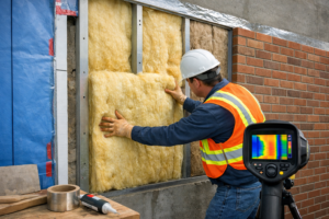
Mid-construction thermography, conducted after the ci is installed and before the cladding goes on, can identify voids in the insulation layer, missing thermal break elements at slab edges and improperly installed bracket assemblies while all of those conditions are still accessible and correctable. The cost of a thermography inspection at this stage on a typical mid-rise commercial project is measured in thousands of dollars.
The cost of the same corrections after occupancy, if they are even physically possible, is measured in hundreds of thousands.
The buildings being designed today under ASHRAE 90.1-2022 will operate for 50 years or more. The thermal bridges that aren’t addressed in the next set of construction documents will conduct heat for every one of those years.
Design the thermal control layer with the same rigor applied to the water and air control layers and calculate the bridges before the structural drawings are issued, not after.