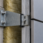
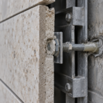
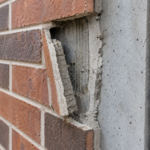
- CI code requirements now force air barrier membranes onto structural steel embed plates on nearly every commercial facade.
- Steel surface conditions including mill scale, primer chemistry and cure state create adhesion variables most specifications never address.
- Two separate approval chains for steel coatings and membrane primers leave chemical compatibility unverified on most projects.
- Thermal cycling causes progressive cohesive bond failure at steel embeds that remains invisible through punch list and early occupancy.
- Defensible specifications must require compatibility documentation, pre-installation adhesion testing and post-occupancy pressurization testing.
The CI Shift That Moved the Air Barrier Onto Steel
Before continuous insulation requirements became the enforcement reality they are today, the air barrier plane on most commercial assemblies terminated at the sheathing or backup wall face. Structural steel embed plates sat inboard of or flush with that plane.
The membrane never touched bare steel. That condition no longer describes most code-compliant commercial work.
ASHRAE 90.1-2022 Section 5. 4 continuous insulation requirements and IBC 2021 Section 1404.3 weather protection provisions have pushed the air control layer outboard in IECC Climate Zones 4 through 8, forcing membrane transitions directly onto embed plates, weld tabs and anchor bracket bearing surfaces.
The geometry is no longer optional. If the air barrier plane lives at the outboard face of the CI layer, every structural penetration through that plane becomes a membrane-to-steel interface condition.
The density of those conditions has grown in parallel. Modern rainscreen, curtainwall and GFRC panel anchor systems generate embed or penetration conditions at regular intervals across the entire facade.
A typical 10-story commercial building with rainscreen cladding carries 400 to 800 individual embed or anchor penetration conditions requiring membrane integration. Each one is a potential air barrier discontinuity.
Each one requires a substrate-compatible, thermally durable adhesive bond to a material that behaves nothing like the sheathing or concrete surfaces membrane manufacturers originally optimized their products for.
What changed the enforcement picture was not a single code cycle but the convergence of prescriptive CI thickness requirements with continuous air barrier mandate language in IECC 2018 and 2021. Prior to that convergence, a project team could satisfy the air barrier requirement at the sheathing plane and satisfy the CI requirement with outboard insulation without ever needing to reconcile the two. The air barrier lived at one plane and the insulation lived at another.
Inspectors accepted that condition because the code language did not explicitly require the two systems to share a plane. That interpretive flexibility has narrowed considerably.
Jurisdictions enforcing IECC 2021 Section C402.5 are increasingly requiring documentation that the air barrier is continuous through the CI layer, which means the membrane must follow the thermal plane outboard and must address every penetration of that plane. The embed plate condition is no longer an edge case.
It is a standard condition on every commercial facade with structural anchors and the specification and detailing practice for that condition has not kept pace with the code reality that created it.
Steel Is Not a Uniform Substrate: Mill Scale, Primer and Paint as Adhesion Variables
Structural steel arrives on site in one of four distinct surface conditions: bare mill scale, shop-applied rust-inhibitive primer, field-applied zinc-rich primer or finish-painted. These are not minor variations.
They are chemically distinct bonding surfaces with different surface energies, different porosity profiles and different mechanical bond potential.
Most self-adhered membrane manufacturer data sheets list “primed steel” as a compatible substrate. That language does nearly no work.
It does not differentiate primer chemistry, film thickness, cure state or topcoat presence. A shop-applied alkyd rust-inhibitive primer at 2-3 mils DFT that has been curing for six weeks is a different bonding surface than a field-applied zinc-rich epoxy primer at 4-6 mils DFT applied three days before the membrane installer arrives.
Both qualify as “primed steel” under the data sheet language.
Mill scale is a particularly problematic substrate that receives inadequate attention in most project specifications. It is an electrochemically active, mechanically weak iron oxide layer formed during hot rolling.
Adhesion to mill scale is not adhesion to steel. The scale itself can delaminate from the base metal under mechanical stress, taking the membrane with it regardless of how well the membrane bonded to the scale surface.
ASTM D4541 pull-off adhesion testing on mill scale versus cured primer surfaces shows significant variance and field-applied primers rarely achieve the cure state assumed in the manufacturer’s laboratory testing protocol. SSPC-SP 2 and SSPC-SP 3 hand and power tool cleaning standards exist precisely because surface condition controls coating performance.
The same logic applies to membrane adhesion. Ignoring it produces predictable outcomes.
The surface energy problem is worth quantifying. Clean, blast-prepared steel has a surface energy in the range of 40 to 50 millinewtons per meter, which is generally favorable for adhesive bonding.
Mill scale drops that figure meaningfully and contamination from cutting oils, forming lubricants or atmospheric oxidation drops it further. Self-adhered membrane adhesives are typically butyl-based or modified bitumen formulations optimized for bonding to porous, relatively high-energy substrates like concrete masonry or glass mat gypsum sheathing.
Those substrates absorb and mechanically interlock with the adhesive in ways that smooth steel surfaces do not. The bond to steel is almost entirely chemical and surface-contact dependent, which means surface preparation quality has an outsized effect on long-term adhesion performance compared to what the same membrane would experience on sheathing.
The cure state variable is one that specification writers consistently underestimate. An alkyd primer applied in a shop environment at 70°F reaches full cure in approximately seven to fourteen days depending on film thickness and ventilation.
That same primer applied in the field at 45°F in November may not reach equivalent cure state for three to four weeks. If the membrane installer follows the primer application within 48 hours, as is common on compressed schedules, they are bonding to a primer that has not developed its full cohesive strength.
The membrane adhesive may bond adequately to the primer surface, but the primer-to-steel interface is the weak link. ASTM D4541 testing at the actual field cure state would reveal this condition.
It is almost never specified or performed.
When the Membrane Primer and the Steel Primer Are Two Different Products From Two Different Trades
Self-adhered membranes applied to steel typically require a membrane-specific contact primer applied over the existing steel coating. The result is a two-primer system.
No single party owns compatibility verification for that system.
The structural steel coating is specified and approved by the structural engineer of record, typically under Division 05 or a project-specific corrosion protection specification. The membrane primer is specified by the envelope consultant or waterproofing specifier under Division 07. These approval chains do not intersect on most projects.
The structural engineer approves the steel coating for corrosion resistance. The envelope consultant approves the membrane primer for adhesion.
Nobody approves the combination.
Membrane manufacturer field approval letters frequently contain language that voids warranty if the membrane is applied over “incompatible coatings. ” That language is not defined in measurable terms.
There is no peel strength threshold cited. There is no chemical compatibility matrix included.
The language functions as liability transfer rather than technical guidance.
The practical gap is this: the membrane installer applies their primer over whatever steel coating exists on the day of installation. They have no chemical compatibility testing.
They have no documentation of the specific steel coating product actually used in the shop or field. AAMA 711-13 addresses self-adhered flashing tape compatibility in general terms but does not resolve the two-trade approval gap that produces this condition on real projects.
ASTM C1305 crack bridging performance is a separate variable that compounds the problem when the membrane must also span the perimeter gap at the embed plate edge. The specification creates the gap.
The field inherits it.
The shop drawing process makes this worse in a specific and predictable way. The structural steel shop drawings are reviewed and approved by the structural engineer of record.
The coating system is documented in those submittals, typically as a product name and specification number. The envelope consultant reviewing the membrane submittals under Division 07 does not receive the Division 05 shop drawing package as a matter of standard practice.
There is no cross-reference requirement in most project manuals. The result is that the envelope consultant approves the membrane and primer system without knowing what coating the membrane primer will be applied over and the structural engineer approves the steel coating without knowing what membrane primer will be applied on top of it.
Both approvals are technically correct in isolation. The combination is never evaluated.
This is not a hypothetical coordination failure. It is the standard condition on most commercial projects and it persists because the project delivery structure does not create a natural intersection point for these two approval chains.
The general contractor is the only party with visibility into both submittals and GCs are not typically equipped or contractually required to evaluate chemical compatibility between coating systems. Closing this gap requires the specification to explicitly assign that coordination responsibility, name the party responsible for obtaining written compatibility confirmation from the membrane manufacturer for the specific steel coating product used and require that documentation before any membrane installation at steel substrates begins.
Cohesive Separation Under Thermal Load: The Failure Nobody Sees at Punch List
Steel embed plates experience thermal amplitude that adjacent masonry or sheathing substrates do not. The thermal mass differential is significant.
A steel plate exposed to direct solar radiation at the outboard face of a CI assembly in IECC Climate Zone 5 can reach surface temperatures exceeding 160°F in summer and drop below 0°F in winter. The seasonal delta-T across that plate exceeds 100°F.
The adjacent sheathing or concrete backup wall experiences a fraction of that range due to higher thermal mass and insulation buffering.
That differential thermal movement generates shear stress at the membrane-to-steel bond line. The stress is cyclic.
It accumulates over heating and cooling seasons. When the bond fails, it fails cohesively within the membrane body or at the primer interface, not at the visible membrane edge.
This is why the failure mode hides.
Cohesive failure leaves membrane material bonded to both the steel surface and the adjacent sheathing in thin, stretched layers. From a standard field QC walk-through perspective, the installation looks intact.
There is no visible edge lifting. There is no obvious gap.
The membrane appears to be doing its job.
The timeline compounds the detection problem. The adhesive bond may appear fully intact at installation and through the first heating and cooling season.
Failure typically becomes detectable as air leakage only after 12 to 24 months of thermal cycling, long after punch list sign-off and often after the project has been occupied. ASTM E2178 air permeance testing and ASTM E1186 air leakage site detection methods can locate the failure plane, but only if someone orders the test.
ASTM D1876 T-peel testing under thermal cycling protocols in a laboratory setting demonstrates the degradation mechanism clearly. The problem is that nobody specifies that testing as a pre-installation qualification requirement on field conditions.
They should.
The coefficient of thermal expansion differential between steel and the membrane body is the mechanical driver of this failure. Structural steel expands at approximately 6.5 millionths of an inch per inch per degree Fahrenheit.
A modified bitumen self-adhered membrane has a significantly higher coefficient, typically in the range of 30 to 50 millionths per inch per degree Fahrenheit depending on formulation. A 4-inch by 8-inch embed plate cycling through a 100-degree temperature range generates linear dimensional change at the steel surface on the order of 0.003 inches.
The membrane bonded to that plate wants to move at a rate five to eight times greater than the steel will allow. That constraint is absorbed as shear stress at the bond interface.
Over dozens of thermal cycles, the adhesive layer fatigues. The failure is not sudden.
It is progressive, which is exactly why it does not register on any single inspection event.
Butyl-based adhesive systems are generally more resistant to this fatigue mechanism than straight modified bitumen formulations because butyl retains elasticity at low temperatures and does not become brittle in the temperature ranges common to Climate Zones 5 through 7. Specifying membrane products by adhesive chemistry type, not just by ASTM E1677 air barrier material classification, gives the project team a meaningful tool for selecting products appropriate to the thermal exposure at steel substrates. Most Division 07 specifications do not make this distinction.
They specify air barrier membranes by performance class and leave product selection to the installer, who selects based on price and availability rather than adhesive chemistry suitability for the specific substrate condition.
Where the Embed Plate Penetrates the Plane: The Three-Dimensional Transition Nobody Details Completely
Through-wall embed conditions create a three-dimensional air barrier transition that flat-detail drawings do not resolve. The membrane must transition from the backup wall face, wrap the embed plate perimeter and seal against the steel element projecting through the insulation plane.
That is three distinct substrate interfaces and two directional changes in a single condition.
The discontinuity occurs at the inboard face of the embed plate. The membrane cannot physically continue around the back of the plate when the plate is welded to a structural member passing through the assembly.
This inboard termination is typically left to field improvisation or omitted entirely from contract documents. I have reviewed dozens of project specifications where the air barrier continuity detail stops at the outboard face of the embed and says nothing about the inboard condition.
Common field resolution is backer rod and sealant at the inboard embed perimeter. This approach fails on two counts.
First, most sealant-only terminations are not air barrier-rated details and are not connected to the interior air barrier system in any documented way. Second, the sealant is applied in a condition with poor joint geometry, variable substrate preparation and no continuous backing that would allow it to function as a true air seal under pressure differential.
The four control layers require continuity; a sealant bead applied to a gap nobody designed is not continuity. It is a field patch masquerading as a detail.
The geometry problem becomes clearer when you trace the air barrier path through the assembly in section and plan simultaneously. In section, the membrane transitions from the backup wall face across the outboard face of the CI layer and wraps onto the outboard face of the embed plate.
That transition is manageable with a self-adhered membrane if the CI is cut cleanly and the plate edge is primed. In plan, the membrane must wrap all four sides of the plate perimeter, which requires cutting and overlapping the membrane at the corners, creating lap joints on a non-planar surface.
Corner lap joints on steel are among the highest-risk conditions in any membrane installation because the membrane must conform to an inside or outside corner while maintaining full adhesive contact on a hard, non-compressible substrate. Membrane manufacturers publish corner patch details for these conditions, but those details assume the corner is accessible and that the adjacent substrate is the same material on both sides of the corner.
At an embed plate, the corner transitions from steel to CI to sheathing within a few inches and the accessibility is often compromised by the structural element projecting outboard.
The inboard face condition is where the detail genuinely breaks down. When the embed plate is welded to a structural tube or wide flange passing through the wall assembly, the inboard face of the plate is not a free surface.
The structural member occupies the center of the plate and the weld perimeter creates an irregular surface condition that no self-adhered membrane can conform to without supplemental fluid-applied material. The weld bead itself is a substrate compatibility problem: weld spatter creates a mechanically rough, chemically active surface with mill scale, oxidation and potential flux residue that is categorically different from the primed plate face.
No membrane data sheet addresses weld bead bonding specifically. The field installer is making judgment calls on a condition the specification never described.
What a Defensible Specification Actually Requires at This Condition
Closing the gap between specification intent and field reality at steel embed conditions requires three things that most project specifications currently omit.
First, the specification must require chemical compatibility documentation between the steel coating system and the membrane primer system before installation begins. This means requiring the membrane manufacturer to review and approve in writing the specific steel coating product used on the project, not a generic category.
If the structural steel coating changes during the project (field touch-up with a different product is common), the approval must be re-issued.
Second, the specification must require pre-installation adhesion testing per ASTM D4541 on representative substrate samples that replicate actual field conditions: the actual steel coating at the actual cure state at the actual ambient temperature range anticipated during installation. Lab data sheets generated under controlled conditions at 70°F and 50% relative humidity do not represent a February installation in IECC Climate Zone 6.
Third, the through-wall penetration detail must be fully resolved in contract documents, not deferred to field coordination. The inboard termination condition requires either a fluid-applied transition membrane that can wrap the full plate perimeter including the inboard face or a pre-manufactured boot or collar detail that connects the outboard self-adhered membrane to the interior air barrier system in a continuous, tested assembly.
Either approach requires coordination between the structural, envelope and waterproofing specifications before the bid documents issue.
The ASTM D4541 testing requirement deserves more specific language than most specifications provide. The test should be performed on steel coupons coated with the actual project coating system, cured for a period that replicates the minimum expected field cure time at the minimum expected installation temperature, then primed with the membrane primer and tested at the ambient temperature range anticipated during the installation window.
Minimum acceptable pull-off values should be stated in the specification, not left to the manufacturer’s discretion. A reasonable threshold based on available adhesion data for self-adhered membranes on primed steel is 15 psi minimum average pull-off strength with no individual reading below 10 psi.
Those numbers are not universal and the envelope consultant should confirm them with the specific membrane manufacturer for the specific product specified, but the specification must name a number. “Adequate adhesion” is not an acceptance criterion.
The fluid-applied transition membrane approach at the inboard embed condition requires its own specification language. The fluid-applied product must be compatible with both the self-adhered membrane it ties into on the outboard face and the interior air barrier system it connects to on the inboard face.
That compatibility must be documented by the manufacturer of the fluid-applied product in writing before application. The application thickness, number of coats and minimum cure time before the self-adhered membrane is lapped onto the fluid-applied termination must be specified.
These are not details that can be resolved in the field on the day of installation. They require pre-construction coordination between the membrane manufacturer, the fluid-applied product manufacturer and the envelope consultant and that coordination must happen before the bid documents issue so that the cost and schedule implications are captured in the contract.
The QC Program That Actually Catches This Failure Mode
Standard field QC for self-adhered membrane installations relies on visual inspection and occasional peel tab testing. Neither method detects cohesive separation under thermal cycling because the failure has not yet occurred at the time of inspection.
The QC program is checking for the right condition at the wrong time.
A QC program that actually catches this failure mode requires post-occupancy pressurization testing per ASTM E2357 as a contract deliverable, not an optional owner add-service. Twelve months post-occupancy is the minimum useful interval; 24 months captures the second thermal cycling season where cumulative bond degradation becomes detectable.
Blower door testing per ASTM E1186 protocols can then locate specific failure points for forensic investigation.
The Chicago project that opened this discussion passed every field QC checkpoint at punch list. The membrane looked correct.
The primer had been applied. The photos showed clean terminations.
The failure was invisible until pressurization testing forced air through bond planes that had separated over two heating seasons. That is not a QC failure in the traditional sense.
That is a specification failure. The QC program was designed to verify installation quality at a single point in time and the failure mode operates on a timeline that single-point inspection cannot capture.
Building the post-occupancy pressurization test into the contract, with specific acceptance criteria tied to ASTM E2178 air permeance limits, is the only way to close that gap. Write it into the specification before the project goes to bid.
The peel tab testing that does occur during installation deserves more rigorous protocol language than it typically receives. Most specifications require peel tabs at some interval, commonly one per 1,000 square feet of membrane, without differentiating between membrane applied to sheathing and membrane applied to steel.
The failure risk at steel substrates is categorically higher than at sheathing and the peel tab frequency should reflect that. A defensible specification requires peel tab testing at every steel embed condition, not at a square footage interval, with the tab applied to the steel-to-membrane interface specifically rather than to the adjacent sheathing.
The tab must be pulled at a 180-degree angle per ASTM D903 and must demonstrate cohesive failure within the membrane body rather than adhesive failure at the steel or primer interface. Adhesive failure at the primer interface on day one of installation is a leading indicator of the cohesive separation failure that will develop over the following 18 months.
It should trigger immediate stop-work and substrate re-evaluation, not a note in the field report.
The infrared thermography option is worth including in the QC specification as a supplemental tool. ASTM C1060 thermographic inspection of insulated building envelopes can detect air movement through failed membrane bond planes under certain conditions, specifically when there is a meaningful temperature differential between interior and exterior and when the air leakage rate is sufficient to create a detectable thermal signature.
Thermography will not detect a bond plane that has separated but is not yet experiencing significant air leakage under ambient pressure differentials. It is most useful as a post-occupancy diagnostic tool after pressurization testing has confirmed that air leakage is present and the investigation is focused on locating the specific failure points.
Specifying thermography as a standalone QC method without pressurization testing is not sufficient. The two methods are complementary, not interchangeable and the specification should describe the sequence in which they are applied.