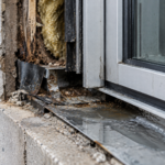
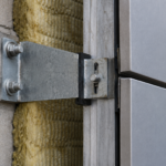
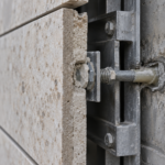
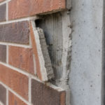
- Trellis anchors installed through fluid-applied WRBs without proper detailing are the leading cause of hidden moisture damage in vegetated facade systems.
- Division 32 and Division 07 specifications almost never cross-reference each other leaving the membrane-to-anchor interface without a responsible party.
- Organic acids from decomposing plant material accelerate zinc depletion and can corrode standard galvanized anchors within five to seven years.
- Type 316 stainless steel is the minimum anchor specification for vegetated facade conditions especially where reclaimed irrigation water is used.
- Contract documents must mandate pre-installation coordination meetings and large-scale penetration details to assign liability before moisture damage appears.
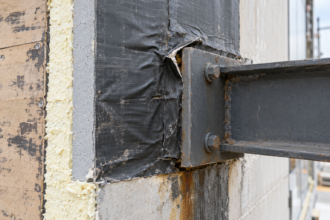
A post-occupancy investigation on a mid-rise institutional building in the Pacific Northwest revealed chronic interstitial moisture accumulation behind a cable-trellis vegetated facade installed over a fluid-applied WRB. The trellis anchor plates had been set directly through the membrane without back-rod or sealant detailing and the irrigation overflow had no defined drainage plane exit.
The failure was not discovered until interior gypsum board on the third floor showed staining two years after substantial completion. Neither the green wall specification nor the facade subcontract had assigned responsibility for the membrane penetration details.
That gap cost the owner a six-figure remediation and a two-year dispute over design liability.
That project is not an outlier. It is the pattern.
The Specification Gap Nobody Owns: How Green Wall Systems Get Layered Over Uncoordinated Envelopes
Green wall and trellis systems are almost universally specified under Division 32 (Exterior Improvements) or carved out to a specialty vendor scope, while the water-resistive barrier lives in Division 07. The CSI MasterFormat boundary between those two divisions is not just an organizational convention; it is where coordination responsibility falls through the floor. The Division 32 vendor has no contractual obligation to understand the membrane below.
The Division 07 subcontractor has no visibility into what the green wall vendor will anchor through after they leave the site.
This division boundary problem compounds on projects where the WRB subcontractor completes work, passes inspection and demobilizes before the green wall vendor ever sets foot on site. The WRB is treated as a closed scope.
The membrane installer has no reason to return, no contractual trigger to review penetration conditions and no financial incentive to flag a problem that belongs to someone else’s schedule. By the time the green wall vendor arrives, the WRB is often covered by continuous insulation or a drainage mat and the anchor locations are being driven by the trellis geometry, not by any knowledge of what is underneath.
LEED BD+C v4.1 Sustainable Sites credits, particularly the Heat Island Reduction credit that incentivizes vegetated facades and green roofs, reward the system selection without requiring any envelope interface documentation as a precondition. The credit language references coverage and albedo, not penetration detailing or drainage plane continuity.
Owners and architects collect the credit. The envelope below absorbs the risk.
Design-build and design-assist delivery models make this worse. The green wall vendor self-specifies anchor details with no envelope consultant review required by contract.
No ASTM standard, no ICC provision and no AAMA document specifically addresses the vegetated facade-to-WRB interface. That absence of a governing standard does not mean the liability is absent.
It means the liability is unassigned until litigation assigns it.
The practical consequence is that the project record contains two complete and internally consistent specifications, one for the WRB assembly and one for the green wall system, that never reference each other and never assign ownership of the plane where they meet. When moisture damage appears, both subcontractors point to the other scope.
The owner’s only recourse is the architect’s coordination obligation, which is often poorly documented in the design agreement and difficult to enforce without a clear standard of care reference. That is the liability structure that produces six-figure remediation costs on projects where the technical fix would have cost a few thousand dollars in sealant and inspection time.
Sequencing the Waterproofing Assembly Before the Green Wall Goes On
The correct layer order for a vegetated facade assembly over a framed exterior wall is: structural substrate, air barrier, WRB or fluid-applied membrane, continuous insulation if present, drainage mat or cavity, cladding attachment and finally the green wall substrate or trellis system. Each layer has a defined function within the four control layers: water, air, vapor and thermal.
The trellis or armature system interrupts this sequence at the cladding attachment plane or, in heavier ballasted systems, at the structural substrate itself. Knowing exactly where the interruption occurs determines which control layers are at risk.
Fluid-applied WRBs require full cure before anchor installation. This is not a suggestion.
Vapor-permeable acrylic membranes typically require a minimum 4-hour recoat window under ideal conditions, but anchor installation into an acrylic fluid-applied WRB requires a full 24-hour cure window at minimum and many silyl-terminated polymer membranes require longer windows in temperatures below 50 degrees Fahrenheit. Fast-track schedules routinely compress these windows.
When an anchor plate is set into an incompletely cured membrane, the membrane deforms around the fastener without bonding to the anchor flange, leaving an unsealed annular gap that no subsequent sealant application will reliably close.
The cure window problem is not hypothetical. On a university science building project in Climate Zone 5A, a green wall subcontractor installed cable termination anchors into a silyl-terminated polymer WRB approximately six hours after application, during a period when overnight temperatures had dropped to 44 degrees Fahrenheit.
The membrane manufacturer’s published data sheet required 48 hours at temperatures above 50 degrees Fahrenheit before penetration work. The anchors were installed on schedule.
The membrane never achieved full adhesion to the anchor flanges. Moisture infiltration was confirmed by infrared thermography during a post-occupancy investigation 18 months later, with wet insulation present at 23 of the 31 anchor locations surveyed.
Drainage plane continuity below the green wall’s lowest course is non-negotiable. ICC 700-2020 National Green Building Standard Section 703 requires that water management assemblies provide a defined drainage path to the exterior.
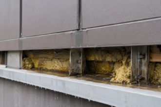
Irrigation water, condensate and wind-driven rain all migrate downward. If the drainage mat or cavity terminates behind a continuous horizontal armature rail without a weep or flashing exit, that water accumulates.
The Pacific Northwest failure described above was precisely this condition: the irrigation overflow had no exit below the lowest trellis rail.
Distinguish between systems that attach at the cladding face and systems that penetrate to the structural substrate. Cable trellis systems and modular panel systems that clip to a secondary framing plane create a different waterproofing consequence than cantilevered planter armatures or heavy ballasted systems that require through-bolts to the structural frame.
The former risks membrane damage at discrete points; the latter risks continuous water infiltration paths through the thermal control layer and into the framing cavity. A cantilevered planter bracket that carries 200 pounds of saturated growing medium and requires a 5/8-inch through-bolt to the structural stud creates a penetration geometry that no field-applied sealant bead will reliably seal under cyclic loading.
That connection requires a fabricated flashing collar designed to the bolt diameter and the membrane product class and it requires design engineer review of the structural load path before the anchor location is fixed.
Every Anchor Is a Membrane Penetration: Detailing Trellis and Armature Attachments Through the WRB
Treat every trellis anchor, cable termination fitting and modular panel bracket that crosses the WRB plane as a through-wall penetration. That means back-rod, bond-breaker tape and a compatible sealant applied in the correct sequence, not a field-applied bead of silicone pressed around an anchor plate after the fact.
ASTM E2112, the installation standard for exterior fenestration, provides the applicable methodology by analogy for through-wall penetration sealing: establish the substrate condition, apply the sealant in a tooled joint geometry that allows movement and verify adhesion before covering the penetration. The same discipline applies here.
The back-rod requirement is frequently omitted in field practice because the anchor plate geometry does not obviously suggest a joint condition. A flat bearing plate sitting against a fluid-applied membrane does not look like a window head joint.
Field crews do not reach for backer rod. The result is a sealant application with no depth control, no three-point adhesion prevention and no defined joint geometry.
When the anchor plate moves under thermal cycling or wind load, the sealant tears at the membrane interface rather than deforming in the joint. Specifying the penetration detail with explicit reference to ASTM C1193 sealant joint geometry requirements, including minimum and maximum depth-to-width ratios, gives the inspector a measurable standard to enforce.
Anchor plate geometry matters more than most specifications acknowledge. Large flat bearing plates trap water against the membrane face and create a capillary pathway under the plate perimeter regardless of sealant quality.
Standoff anchors with sloped or drained base plates reduce ponding risk at the penetration point. This is a geometry selection that should happen at design development, not in a vendor shop drawing review.
Sealant compatibility with fluid-applied WRBs is not assumed. Silicone sealant applied over an acrylic WRB requires surface preparation and primer per ASTM C1193 application guidelines; without primer, adhesion to acrylic substrates is unreliable.
Polyurethane sealants are incompatible with certain vapor-permeable membranes and may inhibit cure or cause surface degradation. The specification must name the WRB product class and require sealant compatibility documentation before anchor installation begins.
Two additional compatibility failure modes appear regularly in field investigations. First, some fluid-applied WRBs contain plasticizers that migrate into adjacent sealant beads over time, softening the sealant and reducing its cohesive strength.
This failure mode typically appears three to five years after installation and is not detectable during initial inspection. Second, UV exposure at the anchor penetration point, which is often higher in vegetated facade conditions because the plant canopy does not fully shade the wall face at installation, can degrade sealant adhesion before the green wall coverage develops.
Specifying a UV-stable sealant formulation at exposed penetration points and requiring the WRB manufacturer to confirm compatibility in writing before installation begins addresses both failure modes at the specification stage.
The anchor installation sequence must appear in the contract documents as a binding requirement: WRB fully cured, anchor installed, penetration sealed and verified, drainage mat installed over the sealed anchor, green wall substrate or trellis attached. If that sequence is not specified, field crews will install anchors and green wall substrate simultaneously and seal the penetrations afterward, if they seal them at all.
Accelerated Corrosion Risk: Why the Green Wall Microenvironment Degrades Standard Anchor Specifications
Vegetated facades create a persistently wet microenvironment at the wall face. Irrigation cycles run on schedule regardless of ambient humidity.
Leaf litter decomposes against the wall face and releases organic acids. Dense planting reduces evaporation and extends moisture contact time with anchor hardware from hours to days.
Standard exterior cladding anchor specifications are not designed for these conditions.
Hot-dip galvanized anchors meeting ASTM A153 Class C or D are the default specification for exterior cladding attachment across most of North America. In a standard rain-screen assembly, they perform adequately because the cavity ventilates and the hardware dries between rain events.
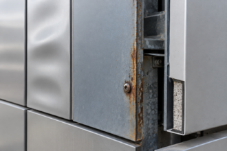
In a vegetated facade condition, zinc depletion accelerates because the organic acids from decomposing plant material attack the zinc coating continuously. Class C galvanizing (1.0 oz/ft² minimum) can fail within five to seven years in dense vegetated facade conditions.
This is not a conservative estimate; it is documented in post-occupancy investigations on green wall systems in IECC Climate Zones 4C and 5A.
The organic acid loading in a mature vegetated facade is not trivial. Decomposing ivy, climbing hydrangea and similar species commonly used on institutional building facades produce humic and fulvic acids as leaf litter breaks down in the cavity space between the plant canopy and the wall face.
Measured pH values at the wall face in dense vegetated facade conditions have been recorded between 4.5 and 5. 8 in field investigations, well below the neutral range in which standard galvanized coatings are rated to perform.
At pH 5.0, zinc dissolution rates increase significantly compared to neutral conditions and the protective zinc carbonate patina that forms on galvanized surfaces in normal atmospheric exposure does not develop reliably in continuously wet, acidic conditions. The five-to-seven-year failure timeline for Class C galvanizing in these conditions is consistent with the electrochemical behavior of zinc at those pH levels.
Minimum specification for anchors in vegetated facade conditions is Type 316 stainless steel for all components within the wet zone. Type 304 is not adequate.
The molybdenum content in Type 316 per ASTM A276 provides the chloride resistance that Type 304 lacks and reclaimed irrigation water frequently carries elevated chloride and sulfate concentrations that would corrode Type 304 within the warranty period.
Reclaimed water use in irrigation systems deserves specific attention in the anchor specification. Many institutional and commercial projects use reclaimed or recycled water for green wall irrigation as part of a water efficiency strategy.
Reclaimed water sources commonly carry chloride concentrations between 100 and 300 mg/L and sulfate concentrations that exceed potable water standards. At those concentrations, Type 304 stainless steel is susceptible to pitting corrosion at crevice locations, specifically at the interface between the anchor base plate and the wall substrate where moisture accumulates and oxygen concentration is reduced.
Type 316 stainless steel with its 2 to 3 percent molybdenum content per ASTM A276 resists pitting in these conditions. Specifying the water source type in the Division 32 irrigation specification and cross-referencing the anchor material requirement in the Division 07 or specialty vendor scope is the only way to ensure that the material selection accounts for the actual water chemistry on the project.
Isolate dissimilar metals. Stainless steel anchors bearing against aluminum subframing create a galvanic couple that accelerates aluminum corrosion.
EPDM or neoprene isolator pads between the anchor base plate and the aluminum framing member break the galvanic circuit. This is a standard detail in coastal cladding assemblies and it belongs in every vegetated facade specification regardless of distance from salt air.
What the Contract Documents Must Do That They Currently Don’t
The liability gap in vegetated facade projects is not primarily a technical problem. It is a contract document problem.
The technical solutions exist. The question is whether the specifications and drawings assign responsibility clearly enough that every subcontractor knows what they own.
The WRB specification in Division 07 must include a penetration detailing section that explicitly addresses vegetated facade anchors and trellis attachments. It should name the anchor installation sequence, require sealant compatibility submittals and prohibit anchor installation before the membrane achieves the manufacturer’s specified cure for penetration work (not just the recoat window).
The Division 32 or specialty vendor specification must reference the Division 07 requirements and require that the green wall subcontractor coordinate anchor locations with the WRB installer before installation begins.
That cross-reference requirement has a practical enforcement problem. On most projects, the WRB installer and the green wall vendor are not in the same room during pre-construction coordination meetings and the general contractor has no contractual mechanism to require joint pre-installation meetings between subcontractors from different divisions unless the specifications explicitly mandate it.
The Division 07 specification should require a pre-installation meeting that includes the WRB installer, the green wall vendor and the building envelope consultant or architect of record before any anchor work begins. The meeting agenda should be specified: confirm WRB product and cure requirements, confirm anchor locations against membrane lap and termination locations, confirm sealant product compatibility and confirm the inspection protocol before drainage mat installation covers the penetrations.
That meeting requirement, written into the specification as a contract obligation rather than a recommendation, creates a documented record that the coordination obligation was assigned and either met or not met.
The facade drawings must show the anchor penetration detail at a minimum scale of 1:5. A schematic detail that shows the anchor plate floating in space without indicating the WRB, drainage mat and sealant geometry is not a coordination document. It is a liability waiver dressed as a drawing.
The 1:5 scale requirement is not arbitrary. At smaller scales, the sealant joint geometry, the back-rod position, the drainage mat termination at the anchor plate perimeter and the relationship between the anchor flange and the membrane surface cannot be shown with enough dimensional clarity to be constructible.
A detail that cannot be dimensionally verified in the field is a detail that will be interpreted differently by every installer who reads it. Penetration details for vegetated facade anchors should show the WRB product class by name or generic type, the sealant joint profile with depth and width dimensions, the back-rod diameter, the drainage mat termination condition at the anchor plate edge and the minimum clearance between the anchor flange and the membrane lap seam.
That level of detail is achievable at 1:5 and is not achievable at the 1:20 or 1:50 scales that appear on most facade elevation drawings.
Assign a named responsible party for the penetration inspection. This can be the building envelope consultant, the special inspector or the WRB manufacturer’s technical representative.
It cannot be left to the general contractor’s quality control process alone, because the GC has no incentive to slow the green wall installation for membrane inspection.
The absence of a governing ASTM or ICC standard for this interface means that the contract documents are the only enforceable standard on the project. Write them accordingly.