- Chronic water intrusion at parapet transitions typically originates in a scope gap between roofing and facade contractors that no trade owns or budgets for.
- Continuous insulation requirements under ASHRAE 90.1-2022 are creating geometry mismatches where roofing and panel water control layers are separated by inches with no physical connection.
- Aluminum panels and TPO membranes expand at dramatically different rates, cyclically stressing any flashing element rigidly connected to both systems.
- Three-sided sealant adhesion at termination bar interfaces is a specification error that guarantees cohesive failure within a few heating and cooling cycles.
- Assigning composite flashing scope to a single trade and requiring a pre-installation meeting with both subcontractors measurably reduces post-occupancy water intrusion claims.
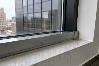
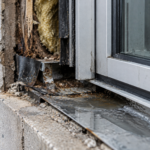
A post-occupancy investigation on a four-story commercial office building reveals chronic water intrusion at the interior parapet corners. Not from the roofing membrane termination.
Not from the metal panel joints. From a 3/8-inch gap between the two systems where neither trade’s scope of work technically ended or began.
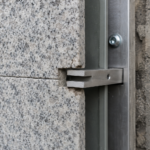
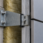
The roofing contractor’s termination bar stops at the top of the cant; the facade contractor’s continuous flashing begins 4 inches above it. What fills the gap is sealant applied by a general laborer during punch list: sealant that has since torn in two planes due to differential thermal movement neither subcontractor modeled.
This is not an unusual project. This is Tuesday.
The Parapet as a Convergence Zone: Why This Detail Is Structurally Different From Every Other Wall Condition
The parapet is the only location in the assembly where the metal panel system transitions from a vertical cladding load path to a condition exposed on three sides: exterior face, interior face and top cap. That three-sided exposure dramatically increases thermal cycling magnitude and introduces differential movement vectors that simply do not exist at mid-wall conditions.
Every other detail in the facade assembly has one primary exposure plane. The parapet has three and they do not move in concert.
Low-slope roofing assemblies and metal panel systems operate under fundamentally different thermal mass assumptions. Roofing membranes are engineered for surface temperatures exceeding 150°F on dark-finish assemblies.
Metal panel substrates cycle through expansion ranges governed by ASCE 7-22 thermal provisions and panel manufacturer movement tables that assume a vertical, single-exposure condition. When you extend the panel system into parapet territory, those assumptions break down immediately.
A dark-finish aluminum composite panel on a south-facing parapet in Phoenix can reach surface temperatures of 180°F or higher on a clear July afternoon and drop to near-ambient overnight. The panel manufacturer’s installation manual was not written with that condition in mind.
Continuous insulation requirements under ASHRAE 90.1-2022 Section 5. 8.
2 are pushing ci thicknesses at parapets to 4 through 6 inches in Climate Zones 4 through 7. That thickness physically displaces the plane of the air and water barrier outward, creating a geometric mismatch between where the roofing contractor terminates the membrane and where the facade contractor anchors the panel system. The two planes are no longer coincident.
They are separated by inches of polyisocyanurate or mineral wool and nobody has drawn a detail that honestly addresses what happens in that gap. On a project using 5.5 inches of polyiso at the parapet in Climate Zone 6, the offset between the roofing membrane termination plane and the panel system’s water control layer can exceed 6 inches measured horizontally.
That is not a gap that sealant resolves. That is a gap that requires a designed transition element with its own attachment, drainage and movement accommodation.
The parapet cap flashing, often specified under Division 07 76 00 as a sheet metal scope item, introduces a fourth party whose work overlaps both trades without being coordinated by either. Three subcontractors.
One detail. Zero shared accountability.
On projects where the sheet metal contractor is a sub-tier vendor to the roofing contractor, the cap flashing installation is sequenced to the roofing contractor’s schedule, not the facade contractor’s. The panel system may not yet be terminated when the cap flashing is set, which means the cap flashing is installed without knowing the final geometry of the panel termination it is supposed to protect.
The result is field-modified flashing that fits neither system correctly.
How Division-of-Work Contracts Create the Coordination Gap
Standard CSI MasterFormat 2016 division structure assigns roofing under Division 07 50 00 and metal wall panels under Division 07 42 00 to separate subcontractors with scopes written to terminate at a shared boundary that is never precisely defined in the contract documents. The drawings show a line.
The specifications describe each system independently. Nobody describes the line itself.
The roofing specification section, typically 07 54 00 for TPO or 07 53 00 for EPDM, will describe membrane termination at the parapet in terms of termination bar height, fastener spacing and sealant application. The metal panel specification section will describe the panel system’s base condition in terms of receiver track height, air barrier termination and sealant joint width.
Neither section references the other. Neither section defines what connects them.
Typical subcontract language under AIA A401-2017 uses phrases like “roof-to-wall transition per drawings” without specifying which trade owns the flashing integration layer, the through-wall flashing receiver or the air barrier continuity connection between systems. AIA A401-2017 assigns coordination responsibility to subcontractors for their own work but does not create a mechanism for resolving scope gaps at interfaces between separate subcontractors.
That gap falls to the general contractor, who treats it as a coordination item rather than a scope item. The distinction matters because coordination items generate meetings and markups on drawings; scope items generate budget, submittals and inspections.
The parapet transition needs to be a scope item. It is almost never treated as one.
The practical consequence: no subcontractor carries budget for the composite detail. Each carries budget for their own system’s termination only.
The roofing contractor terminates per their membrane manufacturer’s requirements. The facade contractor terminates per their panel system’s installation manual.
The interface between those two terminations is addressed, if at all, by whoever is on site last with a caulk gun. That person is rarely a journeyman with any understanding of movement accommodation or air barrier continuity.
On one mid-rise project in the upper Midwest, the punch list sealant at the parapet transition was applied by a laborer using a product that was not listed on the project’s approved materials list, was not compatible with the EPDM membrane it was bonded to and had a rated movement accommodation of plus or minus 7.5%, which is less than a quarter of the movement the joint was experiencing. The warranty claim was filed 22 months after substantial completion.
This is a contractual failure before it is ever a technical one. The specification structure that produces this outcome is not a design error on any individual project.
It is a systemic pattern in how commercial building envelopes are procured and it will produce the same failure on the next project unless the specification is written differently.
Thermal Movement Incompatibility: The Physics of the Failure
Aluminum composite material and aluminum plate panel systems carry a coefficient of thermal expansion of approximately 0.0000131 in/in/°F. A 20-foot-tall parapet panel assembly cycling through a 120°F temperature differential, which is common for dark-finish panels in ASHRAE Climate Zones 3 through 5, generates over 3/8 inch of vertical movement at the panel’s top termination point.
That is not a rounding error. That is the width of a standard termination bar.
On a parapet with a 30-foot run of continuous panel between fixed attachment points, horizontal movement in the same temperature differential exceeds 1/2 inch. Both vectors are occurring simultaneously and they are occurring in a panel that is also being restrained at its base by the roofing system’s termination hardware.
EPDM membranes carry a thermal expansion coefficient of approximately 0.000059 in/in/°F. TPO runs approximately 0.000068 in/in/°F.
Both are additionally constrained by adhesive or mechanical attachment to the roof deck, which means the membrane termination at the parapet face moves in a different magnitude and direction than the panel system above it. The membrane wants to move one way.
The panel wants to move another. The flashing bridging them is caught between two incompatible displacement vectors.
A TPO membrane termination on a 100-foot parapet run cycling through an 80°F differential generates approximately 0.54 inches of linear movement. The aluminum panel system on the same parapet cycling through the same differential generates approximately 0.13 inches.
The two systems are not moving in proportion. Any flashing element that is rigidly connected to both is being cyclically stressed at every temperature change.
Flashing components that bridge the two systems, typically formed aluminum or galvanized steel counter-flashing, are almost never designed with a slip joint or expansion allowance that accommodates both movement vectors simultaneously. The counter-flashing is either fixed to the panel system’s substrate or lapped into the membrane termination.
It cannot do both without a designed slip condition. SMACNA’s Architectural Sheet Metal Manual, 7th Edition, provides expansion joint spacing guidance for metal flashings that is routinely ignored at parapet conditions because the flashing is treated as an accessory rather than a designed component.
SMACNA recommends expansion joints in continuous metal flashings at intervals not exceeding 10 feet for aluminum and 8 feet for galvanized steel in high-exposure conditions. Most parapet counter-flashings on commercial projects are installed as continuous runs without a single expansion joint.
ASTM C719 defines movement accommodation for elastomeric joint sealants as a percentage of joint width, typically rated at plus or minus 25% or plus or minus 50% for high-performance sealants. Most panel system installation manuals specify maximum sealant joint widths that, when you back-calculate the actual movement occurring at the roof-wall interface during simultaneous thermal cycling of both systems, fall outside the sealant’s rated accommodation factor.
A 3/8-inch sealant joint rated at plus or minus 25% accommodates 3/32 inch of total movement. The actual movement at the parapet transition on a typical commercial building in Climate Zone 4 is two to three times that value.
The sealant is not failing because it was installed poorly. It is failing because it was specified to do something physics will not allow.
Flashing Integration Failures: Failure Modes Ranked by Frequency
The most common failure at this interface is sealant tear at the termination bar and counter-flashing interface. This occurs when the roofing membrane termination bar and the facade counter-flashing are connected by a sealant bed that is too thin, too rigid or applied without bond-breaker tape at the base.
The result is cohesive or adhesive failure, typically within three to seven years of installation. The sealant tears because it is being asked to accommodate movement in two planes simultaneously while bonded on three sides.
Three-sided adhesion eliminates the sealant’s ability to deform. This is a specification error, not an installation error.
ASTM C1193, the standard guide for use of joint sealants, explicitly addresses the requirement for bond-breaker tape or backer rod to prevent three-sided adhesion. That requirement is in the standard.
It is routinely omitted from project specifications and almost never enforced during installation inspection. The consequence is a sealant joint that looks correct on the day it is installed and fails predictably within a few heating and cooling cycles.
The second failure mode is air barrier discontinuity at the transition plane. The facade system’s air barrier, typically a fluid-applied or self-adhered membrane behind the panel and the roofing system’s air barrier, typically the cover board or membrane itself, are rarely lapped and sealed to each other at the transition.
The gap between them is a direct air leakage path. Under wind-driven rain conditions, that air leakage path becomes a water entry point because the pressure differential across the assembly drives water inward through any available opening.
Air leakage transports orders of magnitude more moisture than vapor diffusion and this gap is uncontrolled air leakage by design. ASHRAE 90.1-2022 Section 5.
4. 3 requires air barrier continuity at all penetrations, transitions and connections between assemblies.
The parapet transition is explicitly a transition between assemblies. Compliance with that requirement demands a physical material connection between the two air barriers, not proximity.
On projects where the facade air barrier is a fluid-applied product and the roofing air barrier is a self-adhered sheet membrane, the connection requires a compatible transition membrane and a tested lap condition. Most project specifications do not name the transition product or specify the lap dimension.
The third failure mode is cap flashing uplift and pullout. Parapet cap flashings mechanically fastened to the top of the parapet wall without accounting for the combined uplift forces specified in ASCE 7-22 Chapter 26 for roof zone conditions will pull free at the fastener points.
When the cap flashing lifts, it breaks the sealed lap at both the interior and exterior faces of the parapet simultaneously, flooding the parapet wall assembly from the top down. This failure mode is catastrophic because water entry at the top of the parapet bypasses every drainage plane below it.
ASCE 7-22 assigns roof zone uplift pressures that can exceed 60 psf at parapet corners on mid-rise buildings in Exposure Category C. Standard cap flashing fastener schedules, typically #12 screws at 12 inches on center into a wood nailer, are not engineered for those loads.
The wood nailer itself is often the failure point: it splits, the fastener pulls through and the cap flashing lifts as a unit. The fix is engineered fastener spacing calculated against the actual zone uplift pressure, with fasteners into a substrate that has been evaluated for pullout capacity.
What Adequate Coordination Actually Requires
Resolving this interface requires one thing that standard project delivery rarely produces: a single composite detail drawn by someone who understands both systems and is accountable for how they connect. That detail needs to show the air barrier transition explicitly, with laps, termination conditions and the specific product type used to connect the facade air barrier to the roofing air barrier.
It needs to show the movement joint location and design: where the slip condition is, what accommodates it and which trade installs it. It needs to show the ci layer in its actual thickness, the cap flashing in its actual profile and the fastener substrate with its actual material.
A detail that omits any of those elements is not a detail. It is a placeholder that transfers design responsibility to whoever is standing on the scaffold.
The detail also needs to assign ownership. The specification should designate one trade, typically the facade contractor, as the responsible party for the composite flashing assembly at the parapet transition and require that trade to coordinate installation sequencing with the roofing contractor before either system is terminated.
This is not standard practice. It should be.
The facade contractor is the appropriate owner of this scope because the panel system’s performance warranty depends on the integrity of the base condition. A facade contractor who owns the composite flashing detail has a financial incentive to get it right.
A facade contractor who terminates at an arbitrary line on a drawing and hands off to a laborer with a caulk gun has no such incentive.
Pre-installation meetings that include both subcontractors, the general contractor and the envelope consultant at the parapet detail specifically, not as part of a general coordination meeting, produce measurably better outcomes. The conversation forces each trade to articulate where their scope ends and exposes the gap before sealant is the only remaining option.
That meeting should occur after submittals are approved and before either system’s substrate work begins at the parapet. It should produce a written record of scope assignments, sequencing requirements and the specific products that will be used at the transition.
On projects where envelope consultants have required that meeting as a specification condition, the rate of post-occupancy water intrusion claims at the parapet transition drops significantly. The meeting is not a formality.
It is the mechanism that converts a drawing detail into a built condition.
The Continuous Insulation Problem Nobody Is Drawing
ASHRAE 90.1-2022 Section 5. 8.
2 requires continuous insulation at roof-wall intersections to limit thermal bridging at the parapet condition. In Climate Zone 5 and above, effective R-values at the parapet assembly are driving ci thicknesses that push the exterior face of the insulation well beyond the plane of the roofing membrane termination.
The geometry that results from 5 or 6 inches of ci at the parapet means the roofing membrane terminates on the interior face of the ci layer while the panel system’s water control layer exists on the exterior face of the same ci layer. On a project using 5.5 inches of polyiso at the parapet in Climate Zone 6, the horizontal offset between those two planes is greater than the depth of the ci layer itself when the panel system’s furring and air gap are included.
The roofing membrane termination and the panel system’s water control layer are on opposite sides of a 7-inch-thick assembly with no physical connection between them.
Those two planes are not connected by any material in most current details. The ci layer sits between them, unflashed at its top edge, open to water entry from above if the cap flashing fails or is not yet installed.
This is a sequencing and geometry problem that code compliance created and that design details have not caught up to. Energy modeling software confirms compliance with ASHRAE 90.1-2022 at the parapet condition based on the insulation R-value.
It does not flag the water control layer discontinuity that the same insulation thickness creates. The code compliance tool and the building enclosure performance tool are not talking to each other and the project team is not bridging that gap.
The practical solution is a fully adhered self-adhered membrane wrapped continuously from the roofing air and water barrier up and over the top of the parapet wall and down the interior face, installed before the ci layer is applied. This creates a continuous water control layer that the ci layer and cap flashing then protect as secondary and tertiary lines of defense.
It is more material. It requires sequencing discipline.
It works. The self-adhered membrane must be compatible with the roofing membrane it laps onto at the base and with the fluid-applied or self-adhered facade air barrier it connects to on the exterior face of the parapet.