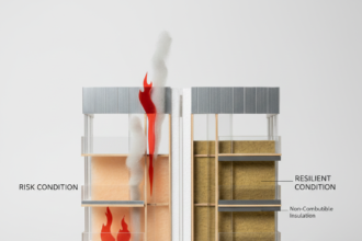

- Most open-joint rainscreen assemblies are never verified for pressure equalization performance, only drainage.
- Cavity depth as low as 3/8 inch after tolerance stack-up can eliminate the ventilation function entirely.
- Bug screens and drip edge profiles routinely reduce effective inlet area to a fraction of what pressure equalization requires.
- Compartmentalization is the most consistently omitted design element and current test standards do not require it.
- Drainage plane continuity at shelf angles and fenestration transitions remains the most concentrated failure point on multi-story buildings.
Sealed vs. Open-Joint Rainscreen Systems: Why Your Cavity Is Not Doing What You Think It Is
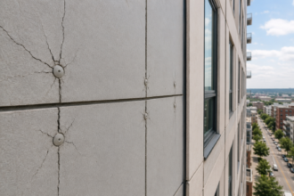
A newly completed seven-story mixed-use building in Climate Zone 5 (Minneapolis) began showing water intrusion at the interior face of the continuous insulation layer within 18 months of occupancy. The rainscreen cladding system was code-compliant on paper: nominal 3/4-inch cavity, open-joint panel system, drainage plane behind the ci.
Investigation revealed the cavity had been effectively reduced to under 3/8 inch after accounting for fastener standoff tolerances and insulation face irregularities. The “open-joint” system had never been evaluated for pressure equalization performance.
Only drainage. The project team assumed open joints provided sufficient ventilation; no one had calculated the inlet-to-cavity volume ratio or verified drainage plane continuity behind the compressed cavity.
The failure was not a code violation. It was a specification failure rooted in a fundamental misunderstanding of how these assemblies actually work.
The Sealed vs. Open-Joint Distinction Is Not a Binary Choice: It’s a Performance Spectrum
Most specifiers treat sealed and open-joint rainscreen assemblies as two discrete categories. They are not.
They represent endpoints on a performance spectrum and most commercial projects land somewhere in the middle without anyone acknowledging that fact.
A sealed rainscreen relies on mechanical drainage as its primary water management strategy. The cavity drains water that penetrates the cladding face; pressure equalization is not a design intent.
An open-joint system, by contrast, is designed to allow controlled air exchange at the cavity face so that the pressure differential across the cladding panel approaches zero under wind loading, eliminating the primary driving force for water infiltration.
The problem is that “open joint” describes a geometry. It does not certify a performance outcome.
A panel system with 3/8-inch open joints can fail to equalize pressure entirely if the cavity depth is insufficient, the inlet area is undersized or the cavity volume is not compartmentalized. ASTM E2273, the standard test method for evaluating drainage efficiency in exterior insulation and finish systems, evaluates exactly one thing: how well water drains.
It says nothing about whether the assembly achieves pressure equalization under dynamic wind loading. Specifiers who select open-joint systems and cite drainage test results as performance evidence are answering the wrong question entirely.
The middle of the spectrum is where most project failures originate, precisely because no one names it. A fiber cement panel system with 1/4-inch open joints and a nominal 3/4-inch cavity is not a sealed system and it is not a pressure-equalized system.
It is a partially vented drainage assembly and its performance under wind-driven rain depends on variables that most specifications never quantify. Panel manufacturers frequently publish drainage test data under ASTM E2273 and water penetration resistance data under ASTM E331 and those two documents together create the impression of a complete performance picture.
They do not. A specifier who reads both and concludes the assembly is pressure-equalized has made a category error that no amount of test data corrects.
The specification must define which performance strategy the assembly is intended to execute and then verify that the physical configuration of the installed assembly is actually capable of executing it.
How Pressure Equalization Actually Works: and What It Requires to Function
The physics are straightforward. Wind impinging on a building face creates a positive pressure zone at the cladding surface.
If that pressure cannot be transmitted into the cavity rapidly enough, a pressure differential develops across the cladding panel and that differential drives water through any available opening: joints, fastener penetrations, panel edges. A pressure-equalized rainscreen cavity eliminates this driving force by allowing cavity pressure to track exterior pressure closely enough that the net differential across the panel face approaches zero.
Three physical conditions must exist simultaneously for this to work. First, inlet area must be sufficient relative to cavity volume so that air can enter and exit the cavity fast enough to match exterior pressure fluctuations during wind gusts.
Second, cavity depth must be adequate to allow air distribution across the cavity face without turbulent short-circuiting directly from inlet to outlet. Third, the cavity must be compartmentalized so that each inlet serves a defined, limited volume rather than an unbounded cavity that no inlet area can adequately pressurize.
The National Research Council of Canada established the foundational framework for this analysis. G.
K. Garden’s 1963 NRC technical paper introduced the concept of the pressure-equalized rainscreen and identified inlet area-to-cavity volume relationships as the governing design parameter.
Subsequent NRC research refined these relationships for buildings of varying height and exposure. The time constant for cavity pressure response is the metric that matters: a cavity that responds slowly to a wind gust will experience a sustained pressure differential during that gust and sustained differential means sustained infiltration potential.
AAMA 508-07 is the primary North American test protocol for pressure-equalized rainscreen wall cladding systems. Its adoption in commercial specification practice remains limited.
Most project specifications reference ASTM E331 water penetration resistance under static pressure or ASTM E547 under cyclic pressure, neither of which evaluates whether the cavity is actually equalizing pressure or simply resisting infiltration through panel-level water management.
Conflating drainage-dominant and pressure-equalization-dominant strategies produces under-designed assemblies. This is the Minneapolis building.
It drains adequately when water reaches the drainage plane. The problem is that the compressed cavity and undersized inlets allow water to reach the drainage plane in the first place.
Understanding the time constant concept is essential for practitioners who are evaluating whether a proposed assembly will actually equalize pressure. The time constant is a function of cavity volume, inlet area and the speed at which exterior pressure changes during a wind event.
A cavity with a long time constant, meaning it responds slowly, will lag behind exterior pressure fluctuations and sustain a differential across the panel face for the duration of each gust. Field wind events are not steady-state conditions; they are sequences of pressure pulses and a cavity that cannot respond within the duration of those pulses is functionally a sealed cavity regardless of what the joint geometry looks like.
NRC researchers measured time constants in physical mock-up testing and found that cavities with inadequate inlet area or excessive volume per inlet exhibited time constants that produced measurable water infiltration under simulated wind-driven rain even when the joint geometry appeared to be open. That research is available and it is not being applied in typical commercial specification practice.
Cavity Depth Requirements: Where the 3/4-Inch Default Fails
The 3/4-inch (19mm) cavity depth that appears in most rainscreen specifications did not originate from pressure equalization research. It derives from drainage mat requirements developed for stucco and EIFS assemblies, where the design intent was drainage, not air exchange.
The industry imported this dimension into rainscreen cavity design without examining whether it was appropriate for a different performance objective.
NRC-derived guidance indicates that effective pressure equalization requires a minimum clear cavity depth of 1 inch (25mm), with 1.5 inches preferred for compartmentalized systems on buildings exceeding four stories. This is not a code requirement in any current North American jurisdiction.
It is best practice derived from empirical research. The distinction matters.
The interaction between continuous insulation thickness and effective cavity depth is where the current energy code environment is creating new failure modes. ASHRAE 90.1-2022 Table C402.
1. 3 prescribes continuous insulation requirements that have increased substantially in Climate Zones 4 through 7 relative to earlier editions.
In Zone 6, for example, mass wall assemblies now require ci levels that push many projects toward 3 to 4 inches of polyisocyanurate or mineral wool outboard of the sheathing. Furring lengths increase accordingly, but effective cavity depth is frequently compromised by insulation face tolerances, fastener deflection under load and substrate irregularities.
The tolerance stack-up is quantifiable. A nominal 3/4-inch cavity with plus or minus 1/4-inch insulation face variation and plus or minus 1/8-inch furring deflection can produce actual cavity depths of 3/8 inch or less at localized zones.
IECC 2021 Section C402.2 establishes parallel ci requirements for jurisdictions not on the ASHRAE compliance path. Both documents are driving furring length decisions across the industry and neither addresses the cavity depth consequences for pressure equalization performance.
The practical consequence of this gap is that furring length is being selected to satisfy thermal compliance and structural attachment requirements without any verification that the resulting clear cavity depth is adequate for the intended ventilation strategy. A project team that specifies 3-inch polyisocyanurate ci in Climate Zone 6 and then specifies a nominal 3/4-inch cavity on top of it has made two independent decisions that are in direct conflict with each other and the conflict is invisible until water appears at the interior face of the ci layer.
Mineral wool ci introduces an additional variable because its faced surface is less dimensionally consistent than polyisocyanurate. Mineral wool boards in the 3 to 4 inch thickness range can exhibit face variation of 3/16 inch or more across a single board and that variation accumulates across a wall face in ways that compress the effective cavity depth at the worst locations, which are typically the locations under the highest wind pressure.
Specifiers who are detailing assemblies with thick ci in high climate zones need to be specifying clear cavity depth as a verified field dimension, not a nominal design dimension and they need to be specifying furring systems with enough adjustability to maintain that dimension across the tolerance range of the insulation product.
Ventilation Opening Sizing: The Calculation Specifiers Are Not Performing
The NRC research established a commonly referenced guidance range of 1/300 to 1/150 of the cladding face area as required open inlet area for pressure equalization. The range exists because the required ratio scales with building height, exposure category and compartment size.
Taller buildings in higher-exposure categories require more inlet area per unit of cavity volume. This is not a fixed number and treating it as one produces errors in both directions.
A simplified example illustrates the gap between what is required and what most open-joint profiles actually provide. A 10-foot-wide by 10-foot-tall compartment with a 1-inch cavity depth has a cavity volume of approximately 1,000 cubic inches.
At the 1/300 ratio, required inlet area equals 0.48 square inches per linear foot of horizontal joint. Now account for what actually happens to that opening in the field: a standard bug screen or mesh reduces effective open area by 40 to 60 percent, horizontal joint profiles with integrated drip edges reduce the effective throat dimension further and compartmentalization is frequently omitted entirely, forcing a single inlet to serve a cavity volume that no realistic joint geometry can adequately pressurize.
AAMA 508-07 Section 5.3 prescribes inlet area requirements for systems tested under that protocol. The UK NHBC Standards Chapter 6.9 prescribes minimum ventilation opening dimensions as a code requirement.
North American building codes and energy codes contain no equivalent requirement. No current edition of the IBC, IECC or ASHRAE 90.1-2022 requires specifiers to calculate inlet area-to-cavity volume ratios for rainscreen assemblies.
This regulatory gap means that undersized ventilation openings pass all required inspections and testing while delivering drainage-only performance in a system specified as pressure-equalized.
The bug screen issue deserves specific attention because it is a consistent source of effective inlet area loss that is almost never accounted for in design calculations. Insect mesh installed at the base of the cavity and at horizontal joint openings is standard practice for pest exclusion and is required by many specifications.
A 1/8-inch galvanized mesh with 50 percent open area, which is a typical commercial product, reduces the effective throat area of any opening it covers by half before accounting for any other geometric restriction. A 3/8-inch open horizontal joint with a 1/8-inch mesh cover and an integrated drip edge profile may deliver an effective inlet area of 0.10 to 0.
12 square inches per linear foot, which is a fraction of the 0.48 square inches per linear foot calculated in the example above. No one is performing this reduction calculation on most commercial projects.
The joint geometry is specified, the mesh is specified, the drip edge profile is selected from a manufacturer catalog and the effective inlet area that results from combining all three is never computed. The assembly is then submitted for review, the reviewer confirms that open joints are present and the system is approved as pressure-equalized without any verification that the actual inlet area is adequate for the cavity volume it is intended to serve.
Drainage Path Design: Why Continuity Behind the Cavity Is Non-Negotiable
Pressure equalization reduces the driving force for water infiltration. It does not eliminate it.
Every pressure-equalized rainscreen assembly must also function as a drained assembly, because equalization is never perfect and transient pressure differentials during extreme wind events will drive some water past the cladding face. The drainage plane behind the cavity is not a backup system.
It is a required functional layer.
Drainage plane continuity fails in predictable locations. At shelf angles, the ci layer is typically interrupted, the drainage plane transitions from one substrate to another and the cavity depth changes as the furring system resets.
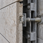
At fenestration rough openings, the drainage plane must integrate with the window flashing system; when the ci layer is thick, this integration requires a pan flashing geometry that many installers are not executing correctly. At penetrations for cladding attachment brackets, the drainage plane must be detailed to shed water around the penetration rather than channeling it inward along the fastener.
The water control layer and the drainage plane are the same element in most commercial assemblies: a fluid-applied or self-adhered WRB over the sheathing. When the effective cavity depth is compressed to 3/8 inch by tolerance stack-up, the drainage function of that cavity is also compromised.
Water that reaches the drainage plane in a compressed cavity has nowhere to drain freely; it sits against the WRB face and increases the hydrostatic pressure on any imperfection in the WRB continuity. The ci layer behind the compressed cavity then becomes a capillary pathway rather than a thermal control layer.
The shelf angle condition is worth examining in detail because it is the location where the most drainage plane failures concentrate on multi-story commercial buildings. At each floor line where a shelf angle is installed to carry cladding dead load, the ci layer is typically cut and the angle is attached directly to the structural frame or sheathing.
The WRB must then transition from the face of the ci above the angle to the face of the ci below the angle, bridging across the angle itself. When the ci is 3 inches or thicker, this transition requires a flashing element that projects outboard of the ci face and that flashing must be sloped to drain and must lap correctly with the WRB on both the upper and lower ci sections.
In field practice, this transition is frequently executed with a self-adhered membrane strip that is applied to the back of the shelf angle and lapped onto the ci face above and below. The problem is that the ci face is not a dimensionally stable substrate for self-adhered membrane adhesion, particularly with mineral wool and the membrane frequently bridges across the angle rather than conforming to it, creating a void behind the membrane where water can collect and where the adhesion bond is relying on tension rather than shear.
A fluid-applied WRB that is applied continuously over the ci face and then detailed at the shelf angle with a reinforcing mesh and a compatible sealant at the angle-to-ci interface performs substantially better in this condition, but it requires a specification that explicitly addresses the shelf angle transition rather than leaving it to installer judgment.
Compartmentalization: The Design Step That Disappears Between Drawings and Field
Cavity compartmentalization is the most consistently omitted element of pressure-equalized rainscreen design. The physics require it.
Without compartmentalization, the inlet area required to pressurize an unbounded cavity on a large building face is not achievable with any realistic joint geometry.
Compartmentalization means dividing the cavity into discrete pressure zones, typically with horizontal fire-blocking or pressure-break elements at each floor line and vertical breaks at defined intervals. Each compartment must have its own inlet area sized to the compartment volume.
This is standard practice in curtain wall design, where pressure-equalized gasket systems are compartmentalized as a matter of course. In rainscreen design, it is frequently absent from construction documents entirely.
The specification-to-field gap compounds the problem. Even when compartmentalization is shown on drawings, the elements that create it (horizontal closure strips, fire-blocking at floor lines, cavity closures at panel terminations) are installed by the framing contractor or the cladding installer depending on the project delivery model and coordination between those scopes frequently fails.
A detail that shows a continuous horizontal closure at each floor line may arrive in the field as an intermittent element with gaps that defeat the compartmentalization entirely.
The curtain wall comparison is instructive and the gap between curtain wall practice and rainscreen practice on this specific point is not explained by any technical rationale. A pressure-equalized curtain wall system is tested under AAMA 501.1 dynamic wind and water testing and the compartmentalization of the pressure-equalized chamber is verified as part of that test.
The test cannot pass without functional compartmentalization. A rainscreen system specified as pressure-equalized is typically tested under ASTM E331 static pressure testing, which applies uniform pressure across the entire test specimen and does not evaluate whether the cavity is compartmentalized or whether each compartment has adequate inlet area.
The test can pass with no compartmentalization whatsoever, because it is testing water resistance at the panel face rather than pressure equalization at the cavity. This is the testing gap that allows non-compartmentalized rainscreen assemblies to carry pressure-equalization claims without any verification.
Until AAMA 508-07 testing is required for systems making pressure-equalization claims, the specification is the only place where compartmentalization requirements can be enforced and that enforcement requires explicit language about compartment dimensions, closure element materials and installation sequence that most current specifications do not contain.