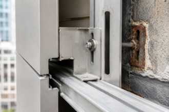
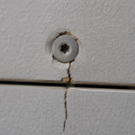
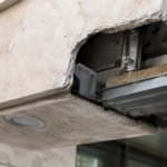
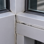
- Splice joints in aluminum storefront framing are the most common field-sealed discontinuities in the air control layer.
- Unprimed anodized aluminum can reduce sealant peel adhesion by 40 to 60 percent compared to properly prepared surfaces.
- Extrusion tolerances can close a designed quarter-inch gap to near-zero making proper sealant consolidation physically impossible.
- ASHRAE 90.1-2022 whole-building air leakage thresholds are now mandatory in several states with certificate of occupancy consequences for failures.
- Probe testing at a minimum of ten percent of splice joints during framing installation catches deficiencies before glazing conceals them.
Sealant Bite Failures at Aluminum Splice Joints
Why Aluminum Extrusion Splice Joints Are the Weak Link in Storefront Air Barrier Continuity
Splice joints in aluminum storefront and window wall framing occur at every condition where two extrusion members terminate and connect: head-to-jamb intersections, intermediate horizontal-to-vertical connections, sill transitions and mid-span coupling sleeves on long runs. These are not incidental details.
They are the primary field-sealed discontinuities in the air control layer of the assembly and they occur dozens of times on a typical four-story storefront elevation.
The distinction between factory-sealed and field-applied joints matters enormously for quality control. Factory conditions allow controlled surface preparation, primer application within specified open times and sealant application under consistent temperature and humidity.
Field conditions do not. Glaziers apply sealant at splice joints in sequence with framing installation, often working around adjacent trades, in ambient temperatures that may be outside sealant application limits and on surfaces that have been handled, contaminated and exposed to weather between cleaning and sealing.
The design assumption embedded in most project specifications is a continuous sealant bead achieving full bite on clean aluminum. That assumption collapses under field conditions almost immediately.
Joint geometry varies, surface preparation is inconsistent and sequencing constraints force applicators to seal joints before the framing is fully plumb and aligned. On a typical mid-rise storefront project, a glazing crew may install and seal forty to sixty linear feet of framing per day.
At that pace, individual splice joints receive thirty to ninety seconds of surface preparation attention before sealant is applied. That is not enough time to execute the cleaning protocol that sealant manufacturer technical data sheets actually require.
Field observation on commercial storefront projects consistently shows that splice joint sealing is treated as incidental work rather than a controlled operation. Applicators carry a solvent-dampened rag and a caulk gun simultaneously.
They wipe the joint, apply sealant and move on. There is no dwell time for solvent evaporation, no primer application and no verification that the aluminum face temperature is within the sealant manufacturer’s application range.
On winter projects in northern climates, aluminum extrusion surface temperatures can drop below 40 degrees Fahrenheit in morning hours even when ambient air temperature reads within the acceptable range. Most silicone sealants require substrate temperatures above 40 degrees Fahrenheit for proper cure and adhesion development.
That condition is rarely checked at splice joints.
AAMA 501.2, which most specifiers cite as the baseline field performance standard for metal curtain wall water leakage, does not address minimum sealant bite depth at splice conditions. That silence is a specification gap that this article addresses directly.
The Surface Oxide Problem: How Mill-Finish and Anodized Aluminum Undermine Adhesion
Aluminum oxidizes the moment it is exposed to air. On mill-finish extrusions, the native aluminum oxide layer that forms is thin, variable in thickness and chemically stable enough to resist adhesion from silicone and polyurethane sealants applied without primer.
Clean the surface with isopropyl alcohol and you temporarily reduce contamination, but the oxide layer reforms within two to four hours under normal ambient conditions. In direct sun or elevated humidity, reformation is faster.
Most field sealant applications occur well outside that window.
Anodized aluminum presents a different but more severe problem. The anodized coating is an engineered oxide layer, not a paint or applied finish.
Class I anodize per AAMA 611-14 requires a minimum coating thickness of 0.7 mil; Class II requires a minimum of 0. 4 mil.
These coatings are chemically inert, dimensionally uniform and specifically designed to resist surface degradation. Those same properties make them resistant to sealant adhesion.
The anodized surface is harder, less porous and more chemically stable than mill-finish oxide, which means sealant mechanical interlocking at the substrate interface is reduced.
Major silicone sealant manufacturer field adhesion data consistently shows that peel adhesion on unprimed anodized aluminum can be 40 to 60 percent lower than on primed or mechanically abraded surfaces. That is not a marginal difference.
It means a joint that appears visually complete may be adhering at less than half the design adhesion value before you factor in bite depth deficiency. Dow, Sika and Tremco publish substrate-specific adhesion tables in their technical data sheets that confirm this range.
Those tables are rarely referenced during specification writing and almost never posted at the jobsite for applicator reference.
The failure mechanism is adhesive rather than cohesive. Silicone sealant has high internal cohesive strength.
When adhesion to the substrate is inadequate, the sealant peels cleanly off the aluminum face rather than tearing through the sealant body. The aluminum surface looks clean after failure.
The sealant bead retains its shape. From a distance, a failed joint and a sound joint are visually indistinguishable.
That characteristic makes post-failure forensics straightforward but makes pre-failure detection through visual inspection essentially impossible.
Thermal cycling accelerates adhesive failure on unprimed anodized aluminum. An aluminum extrusion in a south-facing storefront in a continental climate can cycle through a 100 degree Fahrenheit temperature range between winter night minimums and summer afternoon maximums.
Each cycle imposes a peel stress at the sealant-to-substrate interface. On a primed surface with full design adhesion, that stress is distributed across the bonded area and the joint performs.
On an unprimed anodized surface with 40 percent of design adhesion, cumulative cycling progressively separates the sealant from the aluminum face starting at the edges of the bite zone and progressing inward. The joint does not fail catastrophically.
It degrades gradually and air leakage increases incrementally over the first two to three years of service before the deficiency becomes detectable through occupant complaints or diagnostic testing.
Standard joint design documents specify “clean, dry surface” as the surface preparation requirement. That language does not account for oxide reformation time windows, temperature effects on oxide stability or the practical reality that field cleaning and sealant application are rarely performed by the same worker within the same hour.
Primer requirements on anodized substrates should be mandatory in the specification, not optional language buried in a sealant manufacturer’s technical data sheet.
Extrusion Tolerances and Joint Geometry: When the Gap Is Not What the Drawing Shows
Shop drawings for aluminum storefront systems show splice joints at nominal dimensions. A horizontal-to-vertical splice might be drawn with a 1/4 inch gap, a defined sealant bead width and a clean cross-section showing full sealant contact on both faces.
That drawing reflects the design intent. It does not reflect what gets built.
ASTM B221 governs dimensional tolerances for extruded aluminum profiles used in architectural applications. Tolerance tables in B221 allow for wall thickness variation, profile straightness deviation and end-cut squareness tolerances that individually appear minor but accumulate at splice conditions.
A profile that is within tolerance on straightness and within tolerance on end-cut squareness can still present a gap at the splice joint that varies from near-zero at one corner to 3/8 inch at the opposite corner across a single joint. On a 3-inch deep horizontal extrusion member, a squareness tolerance of 0.010 inch per inch of depth translates to a potential 0.
030 inch end-cut deviation. Stack that against a vertical member with its own squareness deviation in the opposite direction and the joint gap variation across the depth of the profile can exceed 1/16 inch before any installation tolerance is introduced.
When the gap closes below 3/16 inch, applicators cannot physically achieve the tool pressure needed to consolidate sealant against both substrate faces simultaneously. The sealant bead bridges the gap rather than wetting both faces.
The joint looks sealed from the exterior. Probe it and you find a sealant membrane in tension with minimal adhesive contact on one or both aluminum faces.
This bridging condition is particularly common at the interior leg of a splice joint where access is restricted by the framing geometry and the applicator cannot see the sealant contact zone while tooling.
At gaps wider than 3/8 inch, a different failure mode appears: backer rod placement becomes inconsistent and sealant depth-to-width ratios fall outside the 1:2 range that governs joint movement performance. When the gap opens to 1/2 inch or more due to tolerance accumulation in the opposite direction, applicators frequently omit backer rod entirely because the standard 3/8 inch rod does not fit the joint geometry without modification.
Without backer rod, sealant depth is uncontrolled and three-sided adhesion becomes likely. Three-sided adhesion prevents the sealant from stretching uniformly under movement and concentrates strain at the bond line, accelerating adhesive failure at the aluminum interface.
Shop drawings rarely reflect worst-case tolerance conditions at splice locations because detailers work from nominal dimensions. That omission transfers the tolerance problem entirely to the field.
A detailer who draws a 1/4 inch nominal gap has not evaluated whether the combination of extrusion straightness tolerance, end-cut squareness tolerance and installation alignment tolerance can close that gap to zero or open it to 1/2 inch. Building envelope consultants reviewing shop drawings should require detailers to annotate splice joint details with minimum and maximum gap dimensions derived from tolerance analysis, not just nominal design dimensions.
That annotation forces the conversation about sealant access and backer rod compatibility before framing goes up, not after the first pressurization test fails.
Code Pressure Is Rising: How Updated ASHRAE 90.1 and State Energy Codes Are Changing Enforcement
ASHRAE 90.1-2022 Section 5. 4.
3. 1 establishes continuous air barrier requirements for commercial building envelopes and introduces whole-building air leakage testing as a compliance pathway.
The threshold is 0.40 CFM per square foot of gross above-grade wall area at a pressure differential of 0. 3 inches water gauge, tested per ASTM E779 or equivalent methodology.
That threshold is not aspirational. Several jurisdictions are now enforcing it as a mandatory compliance requirement.
Washington, Oregon and Massachusetts have adopted or are actively adopting energy code editions that require demonstrated air leakage rates at or below this threshold. These are not pilot programs.
They are enforcement requirements with inspection protocols attached. When a building fails the ASTM E779 pressurization test, the inspector is now required to identify the source of leakage and document corrective action.
In Massachusetts, the Stretch Energy Code adopted under 780 CMR Appendix AA requires whole-building air leakage testing for commercial occupancies above a defined floor area threshold, with results submitted to the authority having jurisdiction before certificate of occupancy is issued. That submission requirement means a failed test has direct schedule consequences, not just technical ones.
That enforcement posture changes the conversation around aluminum splice joints entirely. Conditions that previously passed under less rigorous visual inspection regimes are now being traced to specific joint failures.
A two-story storefront elevation with forty splice joints, each leaking at a rate consistent with a 3/16 inch bite deficiency, can contribute measurably to a whole-building test failure. To put specific numbers to that contribution: a 3/16 inch gap running the full depth of a 2-inch aluminum extrusion leg, repeated across forty joints, represents approximately 15 square inches of effective leakage area before accounting for pressure differential effects.
At 0.3 inches water gauge, that leakage area can move enough air to push a borderline building over the 0. 40 CFM per square foot threshold on its own.
The enforcement gap is specific: inspectors are now required to trace air leakage sources but lack standardized guidance on sealant bite depth verification at aluminum splice joints. ASTM E779 tells you the building leaks.
It does not tell you where or why. Closing that gap requires field verification methods that most CA scopes do not currently include.
The practical consequence is that building envelope consultants are being called in as forensic consultants after failed pressurization tests on projects where they had no CA role during construction. That reactive engagement is significantly more expensive than the proactive splice joint verification that would have caught the deficiency during framing installation.
How Inspectors Are Missing the Failure: Limitations of Standard Construction Administration Visual Review
A tooled sealant joint at an aluminum splice joint can appear fully formed, continuous and correctly profiled while achieving less than half the specified bite depth on one or both substrate faces. This is not a subtle deficiency.
It is a systematic failure mode that standard visual inspection cannot detect.
Standard CA punch-list review operates on a pass/fail visual assessment: sealant is present, the surface appears continuous and the joint profile looks correct. That assessment tells you nothing about adhesion or bite depth.
A sealant bead that has bridged a tight splice gap without wetting both aluminum faces will look identical to a correctly applied bead from the exterior until it fails under differential pressure or thermal cycling. The tooled surface finish on a bridged joint is indistinguishable from a properly bonded joint because tooling compresses the sealant surface regardless of whether the sealant has achieved contact with the substrate.
An experienced applicator produces a clean, concave tool profile on a bridged joint just as readily as on a bonded one.
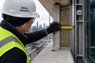
Probe testing and pull-tab adhesion checks are the only reliable non-destructive field verification methods for bite adequacy. A probe test uses a thin blunt instrument inserted along the sealant-to-substrate interface to detect whether the sealant has bonded to the aluminum face or is simply resting against it.
A properly bonded joint resists probe insertion with measurable force and the sealant deforms rather than separating cleanly from the substrate. A bridged or poorly adhered joint allows the probe to slide along the aluminum face with minimal resistance and the sealant lifts away from the substrate without tearing.
Pull-tab tests, where a small tab of sealant is pulled perpendicular to the substrate, reveal whether adhesive failure or cohesive failure governs. Cohesive failure, where the sealant tears through its own body, indicates adequate adhesion.
Adhesive failure, where the sealant peels cleanly off the aluminum face, indicates a bond deficiency regardless of how the joint looks from the exterior. These methods are rarely specified in CA scopes and most CA contracts do not budget time for systematic joint probing at splice conditions.
A CA scope that includes probe testing at ten percent of splice joints on a typical storefront project adds two to four hours of field time per elevation. That is a recoverable cost.
Sealant remediation after a failed pressurization test is not.
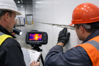
ASTM E1186 covers air leakage site detection using infrared thermography and tracer gas methods. These techniques can locate leakage zones within an assembly but cannot distinguish between a bite depth deficiency and a complete sealant omission.
They identify where air is moving, not why the joint failed to seal. Infrared thermography is particularly limited at aluminum splice joints because the high thermal conductivity of aluminum distributes temperature differentials rapidly across the extrusion, masking the localized thermal signature that would indicate a discrete air leakage path.
Tracer gas methods are more sensitive but require pressurization equipment and specialized detection instruments that most CA teams do not carry as standard field tools. The practical implication is that neither ASTM E1186 method replaces direct mechanical verification at individual splice joints during the construction phase.
What Minimum Bite Depth Actually Means in Practice
The 3/8 inch minimum sealant bite depth specified in most project documents is not an arbitrary number. It reflects the minimum contact area required for a silicone or polyurethane sealant to develop adequate adhesion on an aluminum substrate under cyclic movement and pressure differential loading.
At 3/8 inch bite on a properly prepared surface, the sealant has enough bonded area to resist the peel forces generated by thermal expansion differentials across an aluminum extrusion splice. Aluminum expands at approximately 0.0000131 inches per inch per degree Fahrenheit.
A 10-foot horizontal extrusion member cycling through an 80 degree Fahrenheit temperature range moves approximately 0.126 inches relative to the fixed vertical at the splice joint. That movement imposes a sustained peel load at the sealant bond line.
At 3/8 inch bite with full adhesion, the bond area is sufficient to distribute that load without exceeding the sealant’s adhesion capacity. At 3/16 inch bite, the bond area is halved and the load per unit area doubles, placing the joint at or above the adhesion limit on a primed surface and well above it on an unprimed anodized surface.
Drop below 3/16 inch and the joint is not performing as a sealed joint. It is performing as a bridged membrane, relying on cohesive strength rather than adhesive bond to maintain continuity.
Silicone has excellent cohesive strength, which is precisely why these failures are invisible until tested. The sealant does not fall out.
It simply does not adhere. The membrane spans the gap and maintains the appearance of a sealed joint while transmitting essentially no adhesive load to the aluminum substrate.
Under sustained wind pressure differential, the membrane deflects rather than resisting and air moves around the perimeter of the sealant bead through the interface zone between the sealant and the aluminum face.
Primed surfaces change the calculus significantly. On anodized aluminum with a compatible silicone primer applied within the manufacturer’s specified open time, peel adhesion values recover to levels comparable to abraded mill-finish aluminum.
Dow 1200 OS Primer, Sika Primer-3N and Tremco Spectrem Primer 1 are among the products with published adhesion data on Class I and Class II anodized aluminum showing recovery to 90 percent or better of abraded mill-finish adhesion values when applied within the specified open time window, typically 30 to 90 minutes depending on ambient temperature and humidity. The primer requirement is not a recommendation.
On Class I or Class II anodized substrates, it is a technical necessity that the specification must mandate and the CA scope must verify.
Specifiers who write “clean, dry surface” as the sole surface preparation requirement for sealant at aluminum splice joints are writing a specification that cannot be executed correctly in the field. That language needs to be replaced with explicit primer requirements, maximum time windows between surface preparation and sealant application and hold points for CA verification before joint concealment.
The Specification Fix That Field Conditions Demand
Three weeks before a scheduled ASTM E783 field test is not the time to discover systematic bite depth deficiencies across two full elevations. By that point, remediation requires removing and reapplying sealant at dozens of joints, re-cleaning and priming aluminum surfaces that have been exposed for weeks and re-tooling in conditions that may not match the original application window.
The cost is real. The schedule impact is real.
And the root cause is a specification that did not account for field conditions. On a recent mid-rise commercial project in the Pacific Northwest, post-test remediation of splice joint failures across three storefront elevations required eleven days of glazier time and generated a change order that exceeded the original sealant material and labor budget for the entire storefront scope.
The specification had required “clean, dry surface” preparation and had not mandated primer on the Class II anodized framing system.
The fix starts at the specification stage. Section 07 9200 should mandate primer application on all anodized aluminum substrates, specify maximum elapsed time between surface preparation and sealant application (typically two hours for silicone on aluminum in field conditions) and require probe testing at a minimum percentage of splice joints as a CA hold point before framing is concealed by glazing or interior finishes.
Ten percent is a reasonable minimum sampling rate for probe testing on standard commercial projects. On projects with complex framing geometry, multiple splice joint types or a history of glazing subcontractor quality issues, that rate should increase to twenty-five percent.
The specification should define what constitutes a failing probe test result and require the glazing subcontractor to submit a remediation plan before work in the affected area proceeds.
Shop drawings should include worst-case tolerance analysis at splice conditions, not just nominal gap dimensions. When tolerance stack-up can close a designed 1/4 inch gap to near-zero, the detail needs to show how sealant access is maintained and what minimum gap dimension triggers a field notification before sealant application proceeds.
That notification requirement creates a documented decision point. If the gap is too tight for proper sealant application, the options are to open the gap mechanically, to change the joint detail or to accept a documented deviation with an agreed remediation strategy.
All three options are preferable to discovering the condition after the joint has been sealed and concealed.
The building envelope consultant performing CA on an aluminum storefront system should treat every splice joint as a potential failure point until probe testing confirms otherwise. Assume the joint has not been primed.
Assume the gap is tighter than the shop drawing shows. Assume the applicator cleaned the surface four hours before applying sealant.
Those assumptions reflect field reality far more accurately than the design intent drawing. A CA protocol built on those assumptions will catch deficiencies during framing installation, when correction costs a few minutes of applicator time, rather than after the pressurization test, when correction costs weeks of remediation work and a delayed certificate of occupancy.