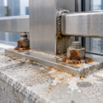
- A forensic investigation found anchor rods corroded to below 40% of original cross-section after just four winters in a Minneapolis institutional building.
- Anchor embedment depths are routinely pulled from manufacturer tables without applying required safety factors for cracked substrates or edge-distance conditions.
- Sealant joints sized at 3/8 inch without bond-breaker tape fail predictably under thermal cycling in IECC Climate Zone 6 and 7 conditions.
- Three field-observable signatures including efflorescence tracking, hairline cracking near anchor pockets and hollow tapping sounds indicate distress before unit displacement occurs.
- Specification corrections including Type 316 stainless anchors, drained pockets and calculated joint widths are the minimum standard for a 30-year service life in northern climates.
Cast Stone Copings: Anchor and Joint Failure at the Parapet
A forensic investigation on a 2019-vintage, six-story institutional building in Minneapolis revealed three displaced cast stone coping units along the south parapet face. Wind uplift was the initial hypothesis.
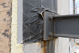
It was wrong. The actual cause was anchor rods corroded to less than 40% of their original cross-section after only four winters, driven by meltwater migrating directly into the anchor pocket through failed sealant joints specified at 3/8 inch.
The failure was not a surprise to anyone who read the original detail closely. It was a predictable outcome of specification decisions that skipped the math.
What Cast Stone Coping Assemblies Are Actually Being Asked to Do
A coping unit at a parapet top carries a specific and demanding functional load. It serves as the primary cap to the parapet wall, intercepting vertical precipitation and redirecting wind-driven water away from the wall assembly below.
It is the first line of defense for the water control layer at one of the most exposure-intensive locations on any building envelope. The parapet top combines maximum solar gain, maximum wind exposure and maximum freeze-thaw cycling into a single assembly location, which is why failures there propagate faster and cost more than failures at any other cladding joint on the building.
The typical assembly consists of the cast stone unit itself, a setting bed or dry-set mortar base, a mechanical anchor (threaded rod or strap type) and sealant joints at unit-to-unit interfaces and at the unit-to-wall interface. Each of those components carries a distinct performance obligation and failure in any one of them accelerates failure in the others.
A compromised sealant joint does not just admit water. It shifts the moisture load onto the setting bed, which was not designed as a drainage plane and then onto the anchor pocket, which was not designed as a sump.
The assembly degrades in sequence, not in isolation.
Cast stone is not natural cut stone and it is not precast concrete, though it shares properties with both. ASTM C1364, Standard Specification for Architectural Cast Stone, sets minimum compressive strength at 6,500 psi and maximum absorption at 6% by weight.
Those thresholds define the material. They do not define the detailing requirements for the assembly.
That distinction matters because specifiers frequently treat C1364 compliance as a proxy for durability, when in fact a unit that meets every C1364 threshold can still fail in service if the anchor and joint details are inadequate for the thermal and moisture exposure at that specific location. A unit absorbing 5.9% by weight and installed over a wet anchor pocket in Climate Zone 6 is a unit that will spall.
C1364 compliance did not prevent that outcome. The detail did not prevent it either.
The setting bed deserves more attention than it typically receives in specifications. Dry-set mortar beds under cast stone copings are frequently installed at inconsistent thickness, creating point-bearing conditions that concentrate load at high spots and leave voids at low spots.
Those voids collect water. ANSI A108.02 requires full mortar coverage for exterior applications, but field verification of coverage under coping units is rarely performed.
When the setting bed fails to provide uniform bearing, the coping unit rocks under foot traffic or thermal cycling, which accelerates sealant joint fatigue at the unit ends. The connection between setting bed quality and sealant joint longevity is direct and it is rarely addressed in the specification.
How Anchor Embedment Depth Gets Underspecified
Two anchor configurations dominate cast stone coping practice. The first is a threaded rod set into the parapet wythe using an adhesive anchor or mechanical expansion anchor, projecting up into a pocket cast or cut into the underside of the coping unit.
The second is a strap or clip anchor fastened to the parapet wall face or top, engaging the coping unit at its side or base. Both configurations depend entirely on the quality of the substrate connection.
A strap anchor fastened to a partially grouted CMU wythe with standard hex-head screws into a hollow core is not an anchor. It is a detail that will look correct on a drawing and perform incorrectly in the field.
The core specification failure is consistent: embedment depth gets pulled from manufacturer minimum pull-out tables without applying the safety factors required for freeze-thaw exposure or substrate condition. A 2.5-inch embedment into CMU backup might satisfy a table value for a controlled laboratory condition.
It does not satisfy the adjusted embedment requirements under ACI 318-19 Chapter 17 for cracked-zone and edge-distance conditions, both of which routinely exist at parapet tops. CMU cores at parapet caps are frequently partially grouted, creating variable substrate strength that adhesive anchor design must account for explicitly under ICC-ES AC308 cracked concrete provisions.
When the evaluation report for the adhesive anchor system is reviewed carefully, the allowable load values for uncracked concrete are typically 30 to 50% higher than the values for cracked concrete. Specifiers who pull the uncracked value and apply it to a parapet CMU wythe are working with a number that does not reflect the actual substrate condition.
Edge distance compounds the problem further. ACI 318-19 Section 17.7 requires reduced capacity calculations when the anchor is placed within 1.
5 times the effective embedment depth from a free edge. At a parapet cap, the anchor rod is frequently within that distance of the top edge of the CMU wythe.
That proximity triggers a breakout capacity reduction that can cut the allowable tension load by 40% or more. That reduction is rarely applied in coping anchor specifications because the specifier is working from a generic detail rather than a location-specific calculation.
The compounding problem is what happens at the anchor pocket itself. Pockets filled with non-shrink grout or sealant rather than properly detailed flashing and drainage create a water trap at the base of the anchor rod.
Water collects there. It has no exit path.
The anchor sits in a continuously wet environment for weeks at a time during freeze-thaw seasons and the corrosion process accelerates accordingly. Non-shrink grout, despite its name, undergoes minor shrinkage during cure that creates a hairline gap at the grout-to-rod interface.
That gap is a capillary pathway. Water wicks into it and sits against the anchor rod shank at the most confined and least-ventilated point in the assembly.
This is not a material failure. It is a detailing failure that was locked in at the specification stage and no amount of quality control during installation will correct a pocket detail that has no drainage provision.
Sealant Joint Sizing: Where the Math Is Skipped
Joint width in a cast stone coping assembly must accommodate thermal movement of the unit itself. This is not the same as filling the gap left by dimensional tolerance, though specifiers routinely treat it that way.
The distinction is consequential. Dimensional tolerance gaps are set during installation to maintain coursing alignment.
Thermal movement joints are sized by calculation to allow the unit to expand and contract without loading the sealant beyond its strain capacity. Conflating the two produces joints that are sized for appearance and fail in performance.
The movement calculation is straightforward. Cast stone has a coefficient of thermal expansion of approximately 5.5 x 10(-6) per degree Fahrenheit.
Apply a 100-degree seasonal temperature delta to a 36-inch unit in Minneapolis and you get approximately 0.020 inches of thermal movement. At 25% sealant strain capacity, that requires a minimum joint width of 3/8 inch.
But freeze-thaw cycling in IECC Climate Zone 6 and 7 conditions repeatedly compresses joints at low temperatures, fatiguing the sealant bond over time. A 1/2-inch joint is the appropriate minimum for that exposure condition, not 3/8 inch.
For units longer than 48 inches, the calculation pushes the required joint width to 5/8 inch or beyond, depending on the temperature delta used. AAMA 2526 provides a joint sizing methodology that accounts for installation temperature, movement range and sealant modulus.
That methodology is rarely cited in masonry coping specifications, even though the exposure conditions at a parapet top are more severe than at most curtain wall joints where the calculation is routinely performed.
The common specification error is a 3/8-inch joint specified uniformly regardless of unit length or climate zone, with no bond-breaker tape behind the sealant. Without a bond breaker, the sealant adheres to three surfaces: both unit faces and the back of the joint.
ASTM C1193 is explicit that three-sided adhesion prevents the sealant from deforming as designed. The sealant tears at the substrate interface rather than stretching across the joint width.
This failure mode is not a product deficiency. It is a joint design deficiency and ASTM C1193 requires joint design to precede sealant product selection, not follow it.
The Minneapolis building specification listed a sealant product in Division 07 and referenced the joint width in Division 04 with no coordination between the two sections. The bond-breaker requirement appeared in neither.
That coordination gap is not unusual. It is the standard condition in project manuals where the masonry spec and the sealant spec are written independently and never reconciled at the joint detail level.
Backer rod selection interacts with bond-breaker function in ways that specifications frequently ignore. Closed-cell polyethylene backer rod does not bond to most sealants and functions as a de facto bond breaker when properly sized and installed.
Open-cell backer rod absorbs water and can transmit moisture to the sealant back face, accelerating adhesion loss. Specifying backer rod type is not a minor accessory decision at a parapet coping joint.
It is a component selection with direct consequences for joint longevity in wet exposure conditions.
The Freeze-Thaw Mechanism: How Water Finds the Anchor
The failure sequence is specific and repeatable. The sealant joint fails in tension or compression cycling.
Water enters the unit-to-unit interface. It migrates to the anchor pocket via capillary action through the setting bed or grout.
Once water contacts the anchor rod and surrounding substrate, freeze-thaw cycling does the structural damage. The sequence does not require a large volume of water.
Capillary transport through a 0.010-inch crack in a sealant bond line is sufficient to keep an anchor pocket wet through an entire freeze-thaw season. The water does not need to flood the pocket.
It needs only to be present at the moment of freezing.
Water expanding to ice in a confined pocket generates approximately 2,000 to 4,000 psi of expansive pressure. The tensile capacity of a cast stone unit face in flexure is typically 400 to 700 psi.
The math is not close. Spalling initiates at the anchor pocket and progresses outward, often appearing as hairline cracking radiating from the anchor location before any visible displacement occurs.
By the time units shift, the anchor cross-section has been compromised for at least one or two seasons. The displacement event that triggers a service call is the end of a degradation sequence that began at the first winter after sealant joint failure.
In the Minneapolis case, the sealant joints showed visible surface crazing by the end of the first winter, which is consistent with three-sided adhesion failure under initial thermal cycling. Water entry into the anchor pockets likely began in year two.
The anchor cross-section loss to below 40% occurred over years three and four. The unit displacement that prompted the investigation occurred in year five.
The assembly communicated its distress for four years before anyone looked.
Climate data makes this worse than older assemblies were designed to handle. NOAA U.
S. Climate Normals updated in 2020 using the 1991-2020 baseline show that freeze-thaw cycle frequency (daily crossings of 32 degrees Fahrenheit) increased by 10 to 18% across Upper Midwest and Great Lakes regions compared to the 1981-2010 normals.
Assemblies detailed to those older assumptions are now cycling more frequently than the original design anticipated. A parapet coping assembly in Chicago that was designed for 55 freeze-thaw cycles per year based on 1981-2010 data is now experiencing 62 to 65 cycles per year.
That increase does not sound large. Applied to a sealant joint already operating near its fatigue limit, it accelerates bond failure by a measurable margin.
Anchor material selection compounds the problem. Type 304 stainless steel is commonly specified and commonly inadequate.
Type 304 is susceptible to crevice corrosion in chloride-bearing meltwater environments, which is precisely the condition inside a wet anchor pocket on a parapet in a northern climate where deicing salts are present. Chloride ions from road salt aerosols and rooftop deicing applications concentrate in the meltwater that enters anchor pockets.
The chloride concentration in that water is not dilute. It is sufficient to break down the passive oxide layer on Type 304 in the confined geometry of an anchor pocket, where oxygen availability is limited and the corrosion cell can sustain itself.
ASTM A276 covers both grades. Type 316 is the minimum appropriate specification for exposed parapet anchor conditions.
The molybdenum content in Type 316 provides the chloride resistance that Type 304 lacks in crevice exposure conditions. This is not a conservative recommendation.
It is the correct call for that exposure category and the cost difference between the two grades at the quantity of anchor rods used in a coping assembly is negligible relative to the cost of a forensic investigation and replacement program.
Reading the Failure Patterns: Diagnostic Indicators in the Field
Three observable signatures indicate anchor and joint distress before unit displacement occurs. Recognizing them early is the difference between a targeted repair and a full coping replacement.
Each signature is visible without destructive investigation if the inspector knows the specific locations and orientations to examine. All three are routinely missed during standard annual facade inspections because inspectors are looking at the coping face rather than the underside and the joint interfaces.
The first is efflorescence tracking from beneath the coping unit at the parapet face, particularly concentrated at the unit-to-unit joint locations. Efflorescence at those specific points indicates water is entering the joint, migrating through the setting bed and carrying soluble salts out through the masonry face below.
Uniform efflorescence across the parapet face suggests a different water entry path, typically through the coping unit itself or through the bed joint at the top course of masonry below the coping. Localized efflorescence at joint intervals points directly to sealant joint failure.
The salt deposit pattern is diagnostic: a vertical streak descending from the joint location, often with a slight lateral spread at the base where the water slows and evaporates. Calcium carbonate is the most common deposit in CMU-backed assemblies.
Calcium sulfate deposits, which appear whiter and more crystalline, indicate water contact with portland cement-rich grout or mortar in the anchor pocket or setting bed.
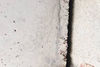
The second is hairline cracking at the underside of the coping unit near the anchor pocket location. This cracking pattern is easy to miss from grade.
A borescope or close-range inspection from a lift will reveal it. The crack orientation matters: radial cracking from a point source indicates freeze-thaw expansion at the anchor pocket, while longitudinal cracking parallel to the unit length suggests differential thermal movement between the unit and the setting bed.
A third crack pattern, transverse cracking perpendicular to the unit length at the anchor pocket location, indicates bending stress in the unit caused by anchor rod restraint against thermal expansion. That pattern means the anchor rod is engaged in a load path it was not designed to carry, which accelerates both rod fatigue and pocket spalling simultaneously.
The third is a hollow sound when the coping unit is tapped with a rubber mallet, indicating debonding from the setting bed. Debonding alone does not mean the anchor has failed, but it removes the friction component of the unit’s resistance to lateral displacement, leaving the anchor rod as the only restraint.
An anchor already compromised by corrosion cannot carry that load alone. The tapping survey should be conducted systematically, starting at the unit center and moving toward each end, noting the transition point where the sound changes from solid to hollow.
A unit that sounds hollow across more than half its length has lost effective setting bed contact and is relying on the anchor for both lateral and vertical stability. That condition warrants immediate investigation of the anchor condition, not deferred maintenance scheduling.
Specification Corrections That Actually Hold in the Field
The fixes are not complex. They require discipline at the specification stage and verification at the shop drawing review stage.
The specification corrections listed here are not aspirational. They are the minimum requirements for an assembly that will perform through a 30-year service life in a northern freeze-thaw climate.
Each one addresses a specific failure mode identified in the field record of cast stone coping failures across the Upper Midwest and Great Lakes regions over the past two decades.
Anchor embedment into CMU backup should be specified at a minimum of 4 inches with full-depth grout in the receiving core, not 2.5 inches into a partially grouted wythe. Adhesive anchors must be specified with ICC-ES AC308 compliance documentation for the specific substrate condition, including cracked-zone provisions.
The evaluation report number should be required on the shop drawing submittal, not just the product name. Strap anchors should be hot-dip galvanized at minimum in IECC Climate Zone 5 and above; Type 316 stainless is the correct specification for zones 6 and 7 where chloride exposure from deicing is routine.
Hot-dip galvanizing per ASTM A153 provides a zinc coating thickness of 3.1 mils minimum on threaded fasteners, which is meaningfully more protective than electroplated zinc coatings that are sometimes substituted in the field without drawing attention during inspection.
Anchor pockets must drain. A weep hole or open vertical joint at the low point of each anchor pocket is not optional in freeze-thaw climates.
It is the detail that prevents the pocket from becoming a water trap. The weep opening should be a minimum of 3/16 inch in diameter and should be located at the lowest point of the pocket geometry, which requires the pocket to be cast or cut with a positive slope toward the weep.
A flat-bottomed pocket with a weep at the side wall will retain water at the center. The geometry must direct water to the weep, not just provide one.
Sealant joint width must be calculated for the specific unit length and climate zone temperature delta, not defaulted to 3/8 inch. Bond-breaker tape is a required component, not an optional accessory.
Closed-cell polyethylene backer rod must be specified by type, not just by diameter. The shop drawing submittal should include the joint movement calculation, not just a sealant product data sheet.
Requiring that calculation on the submittal forces the installer and the manufacturer’s representative to confirm that the specified joint width accommodates the actual movement range for the unit length and climate zone in use. That single submittal requirement catches the most common sizing error before the units are installed.
The Specification-to-Field Gap at Parapet Tops
Every one of the failure modes described here is visible in the original construction documents if you know what to look for. The Minneapolis building had a detail that showed 3/8-inch joints, 2.5-inch anchor embedment into CMU and no bond-breaker notation.
The sealant product was specified after the joint width was set. The anchor material was Type 304. None of those decisions violated a code requirement in force at the time of permitting.
All of them were wrong for that exposure condition. The building passed every required inspection.
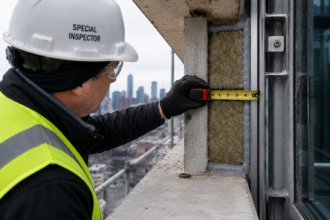
The inspector verified that coping units were installed and anchored. The inspector did not verify anchor embedment depth, anchor material grade, joint width calculation or bond-breaker installation, because none of those items appear on a standard masonry inspection checklist and none of them are required to be documented in a special inspection program unless the structural engineer of record specifically includes them in the statement of special inspections.
That gap between what the specification required and what the inspection program verified is where the failure lived. The specification was inadequate.
The inspection program would not have caught the deficiencies even if the specification had been correct, because the inspection program was not written to look for them. Closing that gap requires coordination between the specification writer and the special inspector at the project outset, with explicit inspection hold points for anchor embedment verification before pockets are grouted and for bond-breaker installation verification before sealant is applied.
Both of those hold points require the work to stop and be documented before proceeding. Both of them are routinely omitted from masonry special inspection programs on institutional projects.
The parapet top is the single location on a building envelope where the water control layer, the anchor system and the sealant joint all converge at maximum thermal and freeze-thaw exposure. Assemblies at that location do not get the benefit of the doubt.
Detail them for the worst conditions that climate zone will deliver over a 30-year service life, because those conditions are now arriving more frequently than the normals used to suggest. The 2020 NOAA Climate Normals are the current baseline for that calculation.
They will be updated again in 2030 and the trend in freeze-thaw cycle frequency across northern climates is not moving in a direction that makes older assembly assumptions more conservative. The specification written today needs to account for that trajectory, not the conditions that prevailed when the last generation of coping details was drafted.