GFRG on Exterior Facades: Where the System Fails
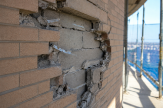
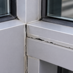
A forensic investigation on a 2021 mid-rise mixed-use project in Charlotte, North Carolina revealed widespread panel delamination and anchor pullout across a decorative GFRG cornice band just 26 months after substantial completion. The specifying architect had substituted GFRG for GFRC based on a manufacturer’s literature package that prominently featured exterior renderings but cited only ASTM C1396 test data, a standard written exclusively for interior gypsum board.
The failure exposed a systemic specification gap that is now repeating itself across dozens of similar projects from Toronto to Phoenix.
What GFRG Actually Is: And What It Was Designed to Do
GFRG is a cast architectural product built on an alpha or beta gypsum matrix reinforced with alkali-resistant glass fiber strands, typically at 3 to 5 percent fiber by weight. That composition makes it acoustically dense, dimensionally stable in controlled environments and capable of reproducing complex classical profiles at a fraction of the cost of carved stone or precast concrete.
It is not GFRC. The distinction matters enormously.
GFRC uses a Portland cement matrix, which gives it inherent alkalinity, compressive strength and a fundamentally different relationship with moisture. GFRG uses calcium sulfate dihydrate (CaSO4·2H2O) as its binder and that chemistry is the root of every exterior performance problem this article addresses.
The validated use environment for GFRG is interior architectural elements: columns, domes, cornices, ceiling coffers and similar decorative assemblies where relative humidity stays below 70 percent and anchor loads are predictable and static. ASTM C1396/C1396M, the standard most often cited in GFRG submittals, is explicit about this.
Its scope statement confines it to gypsum board products for interior use. Applying C1396 data to an exterior facade application is not a conservative interpretation of the standard; it is a misapplication.
Alpha gypsum, the higher-density variant used in most architectural GFRG casting, achieves compressive strengths in the range of 5,000 to 8,000 psi under dry laboratory conditions. Those numbers appear in manufacturer data sheets and they are accurate, but they are dry-state values.
The same matrix tested at 90 percent relative humidity shows compressive strength reductions of 30 to 50 percent depending on fiber loading and casting density. No manufacturer data sheet encountered in forensic review has presented both values side by side for comparison.
The dry-state number is the one that travels through the submittal package.
Beta gypsum, used in lower-cost GFRG products, starts from a weaker baseline and degrades faster under moisture exposure. The distinction between alpha and beta matrix rarely appears in submittal documentation, which means the design team reviewing the package cannot determine which product chemistry is actually being proposed.
Most North American GFRG manufacturers limit exterior use in their product data sheets. That limitation rarely appears in the submittal packages forwarded to design teams during construction documents review.
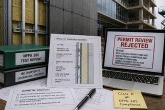
How the Conflation Happens: The Specification Pipeline Failure
The substitution pathway follows a consistent pattern. A contractor or product representative proposes GFRG as a value engineering alternative to GFRC or precast late in design development or during construction documents, when schedule pressure discourages detailed technical review.
The architect accepts the substitution based on a cut sheet package that includes exterior application photography, profile options and pricing. The envelope consultant, if one was retained at all, never sees the substitution because it arrived through the submittal log rather than a formal RFI process.
The document gap is structural, not accidental. Manufacturer cut sheets routinely show GFRG installed on building exteriors in marketing photography while citing only ASTM C473 and C1396 performance data, both of which are interior-analog test methods.
Nothing in the package flags that disconnect explicitly. A design team without deep material knowledge has no reason to question it.
The CSI MasterFormat placement compounds the problem. GFRG is typically specified under Division 09 54 00 (Gypsum Facings), which routes it through the finishes review workflow.
Division 07 42 00 (Metal Composite Material Panels) and the surrounding Division 07 sections trigger envelope consultant review as a matter of standard practice on most projects. Division 09 does not.
The specifier responsible for moisture protection never touches the submittal. The result is a facade material evaluated entirely by reviewers whose expertise is interior finish quality, not water control layer continuity or freeze-thaw durability.
Projects where a facade engineer was retained but scoped only to curtain wall and glazing systems show the same gap. GFRG accent panels fall outside the scope of work by contract and no one flags the overlap.
The timing of the substitution request is not incidental. Value engineering proposals that arrive during the construction documents phase land when the project team is under maximum production pressure and the owner is focused on GMP negotiations.
A substitution that saves $80,000 to $120,000 on a decorative cornice band receives a fraction of the technical scrutiny it would have received during schematic design, when the schedule had room for material research. Contractors and product representatives understand this dynamic.
The proposal is structured to be easy to approve, not easy to evaluate.
The photography in manufacturer literature deserves specific attention. Images showing GFRG on building exteriors are almost universally taken within the first 12 to 18 months of installation, before moisture cycling has progressed far enough to produce visible surface distress.
A panel that photographs well at month 14 may be in active delamination by month 30. The literature captures the installation, not the performance history. Design teams treating those images as evidence of exterior durability are drawing a conclusion the images cannot support.
The Moisture Absorption Problem: What the Test Data Actually Shows
ASTM C473-19 measures surface water absorption and humidified deflection under controlled laboratory conditions designed to simulate interior environments. It does not simulate freeze-thaw cycling.
It does not simulate wind-driven rain at ASTM E331 test pressures. It does not simulate the sustained wetting that occurs at a parapet cap, a cornice drip edge or a panel joint that has lost sealant continuity after two winters of thermal movement.
The test was not designed to answer the question “will this panel survive on a building exterior in IECC Climate Zone 5.” Citing C473 data to support an exterior application answers a different question entirely.
The absorption differential between GFRG and GFRC is significant and well-documented in forensic testing. Standard GFRG panels absorb 15 to 25 percent of their dry weight in water under prolonged exposure.
GFRC panels, formulated with Portland cement matrix and often with silica fume or polymer additives, typically absorb 8 to 12 percent under comparable conditions. That gap is not a minor performance variable.
It is the difference between a panel that sheds a rain event and one that retains it.
The freeze-thaw failure mechanism is straightforward physics. Water expands approximately 9 percent upon freezing.
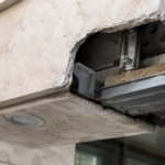
A GFRG panel that has absorbed moisture at the matrix level generates internal tensile stress during each freeze cycle that the gypsum binder cannot resist. The AR glass fiber reinforcement delays catastrophic fracture but does not prevent progressive matrix degradation.
Cycles compound. What begins as hairline cracking at panel edges becomes delamination within two to three heating seasons in Climate Zones 5 through 7.
ASTM C666, the standard test method for resistance of concrete to rapid freezing and thawing, provides a protocol that would be directly applicable to evaluating GFRG exterior durability. The test subjects specimens to 300 freeze-thaw cycles and measures dynamic modulus of elasticity at regular intervals to track progressive degradation.
No GFRG manufacturer encountered in forensic practice has published C666 data for their product. The absence of that data is itself diagnostic.
A product positioned for exterior use on buildings in Minneapolis, Chicago or Toronto should be able to survive 300 laboratory freeze-thaw cycles. The fact that no manufacturer has tested to that protocol suggests the result would not support the marketing position.
Coatings are the most common proposed mitigation and the least defensible one. Elastomeric and acrylic topcoats applied over GFRG do not create a validated exterior system.
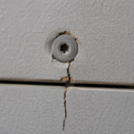
They create a coating-dependent assembly where the failure point shifts to every joint, fastener penetration and panel edge where the coating is discontinuous. Those locations fail.
The timeline is not a question of whether; it is a question of which winter.
Field observations from remediation projects consistently show that coating failures initiate at panel-to-panel joints where sealant has undergone thermal cycling and lost adhesion to the substrate. Once the sealant joint opens, water tracks behind the coating at the panel edge and enters the matrix directly.
The coating on the panel face remains visually intact while the matrix behind it is actively absorbing water. Infrared thermography during a post-rain inspection reveals the moisture distribution that visual inspection misses entirely.
By the time surface staining or efflorescence appears, the matrix degradation is already well advanced.
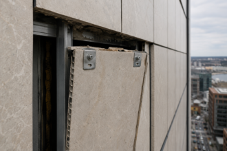
Anchor Pullout Risk: The Structural Consequence of Moisture Degradation
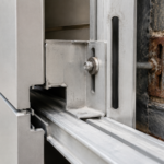
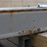
GFRG exterior panels are typically back-anchored to a steel or aluminum subframe using embedded inserts or through-bolt connections cast into the panel during fabrication. The panel’s tensile and shear capacity at the anchor zone is the critical load-transfer point for wind-induced component and cladding (C&C) pressures calculated under ASCE 7-22 Chapter 30. In dry-state laboratory conditions, those anchor zones perform reasonably well against the published manufacturer values.
The problem is that dry-state conditions do not persist on an exterior facade.
As the gypsum matrix absorbs water and softens, anchor pullout resistance degrades nonlinearly. Forensic pull tests on degraded GFRG panels have recorded 40 to 60 percent reductions in pullout capacity relative to dry-state values.
A panel engineered to resist design wind pressures using manufacturer anchor data has, after two to three seasons of moisture cycling, a real-world capacity that may not meet code-minimum C&C requirements under ASCE 7-22. No reduction factor for moisture-degraded capacity exists in any published ASTM or ICC-ES protocol, because no such protocol has been developed for GFRG exterior applications. The facade engineer applying dry-state data is not being careless; the industry simply has not produced the tools to do this correctly.
ASCE 7-22 Chapter 30 requires that C&C pressures be calculated at the tributary area of each panel, accounting for corner and edge zone amplification factors that can increase design pressure by 50 to 100 percent relative to field zone values. A cornice panel at a building corner in Charlotte, where the Charlotte project was located, sits in a pressure zone where design wind loads are substantially higher than the field zone values that may have been used informally to evaluate the substitution.
If the anchor capacity assessment used field zone pressures and the panel is physically located in a corner zone, the engineering basis for the substitution was wrong before moisture degradation entered the equation.
The progressive failure pattern is consistent across forensic files. Anchor zone cracking initiates at panel corners and edges, where stress concentrations from thermal movement and wind pressure are highest.
Those cracks open pathways for additional moisture ingress directly into the anchor zone. Matrix degradation accelerates.
Pullout capacity continues to drop. The Charlotte cornice failure followed this sequence precisely and similar files from projects in Toronto, Chicago and Denver show the same progression within the same 24 to 36 month window.
Embedded insert selection compounds the risk. Threaded inserts cast into GFRG panels during fabrication rely on mechanical interlock with the surrounding matrix.
As the matrix softens under moisture exposure, the bearing area around the insert loses stiffness and the insert begins to rotate under load before it pulls out. Pull tests on dry specimens measure the capacity of a rigid matrix.
Pull tests on moisture-conditioned specimens measure a fundamentally different load-transfer mechanism. The two results are not comparable and using dry-state insert data to justify an exterior application is a category error with structural consequences.
The structural risk is not theoretical. A detached cornice panel at parapet height is a life-safety event.
The Specification Correction: What a Defensible Approach Requires
Stopping the specification pipeline failure requires intervention at three points. First, any substitution of GFRG for GFRC or precast in an exterior application must trigger mandatory envelope consultant review, regardless of which CSI division the product occupies.
The division placement is an organizational convention, not a performance classification. Second, the substitution request must include exterior-specific test data: freeze-thaw cycling per ASTM C666 or an equivalent protocol, water penetration resistance per ASTM E331 as a system assembly and anchor pullout data from moisture-conditioned specimens.
If the manufacturer cannot provide that data, the substitution is not technically supported.
Third, the project specification should explicitly require that GFRG exterior applications be reviewed against the four control layers: water, air, vapor and thermal. A decorative cornice band is not exempt from water control layer continuity requirements simply because it reads as an architectural accent rather than a primary cladding element.
The joint treatment, sealant selection and back-surface drainage path all require the same scrutiny applied to any other cladding attachment in the assembly.
The sealant specification for decorative panel joints warrants specific attention. Many GFRG installations use paintable acrylic latex caulk at panel joints because it matches the coating system and is easy to apply.
Paintable acrylic latex is not a facade sealant. A joint in an exterior cladding assembly that experiences thermal movement, wind-induced racking and seasonal moisture cycling requires a sealant meeting ASTM C920 Type S or M, Grade NS, Class 25 or better, with a use designation of NT (non-traffic) and a substrate compatibility confirmation from the sealant manufacturer for the specific GFRG coating system in use.
That specification language exists in Division 07 92 00 and it should be cross-referenced explicitly in any Division 09 section covering exterior decorative panel applications.
The back-surface drainage path is consistently overlooked in GFRG exterior installations. GFRC and precast panel systems routinely incorporate a drained and back-ventilated cavity between the panel and the substrate.
GFRG installations frequently do not, because the product was designed for direct attachment to interior framing where drainage is irrelevant. When a GFRG panel is installed tight against a substrate with no drainage plane, any water that enters through a joint failure or coating breach has no exit path.
It saturates the panel from the back face inward, accelerating matrix degradation faster than front-face exposure alone would produce.
The practical reality is that most GFRG manufacturers are not positioned to provide exterior-grade performance data because their product was not designed for exterior use. That is not a criticism.
It is a scope statement.
What This Means for the Next Project Crossing Your Desk
The wave of GFRG exterior failures now appearing in forensic practice is not a manufacturing quality problem. The panels are performing exactly as their chemistry predicts.
The failure is a specification failure and it is repeating because the substitution pathway is fast, the cost savings are real and the consequences are delayed long enough that the specifying team rarely connects the failure to the decision.
If a GFRG exterior application arrives on your desk as a value engineering substitution, the correct response is not to request additional submittals. The correct response is to require a material substitution that uses a cement-based matrix, document the technical basis for the rejection in writing and confirm that the envelope consultant’s scope explicitly covers the decorative panel system regardless of its CSI division assignment.
The Charlotte project cost more to remediate than GFRC would have cost to install. That arithmetic repeats every time.
The written rejection documentation matters beyond the immediate project. When a substitution is rejected verbally or allowed to expire without formal response, the contractor’s record shows only that the substitution was not approved, not that it was technically evaluated and found deficient.
If the panel system is installed anyway through a field decision or a miscommunication in the submittal log, the absence of a written technical rejection makes the design team’s liability position substantially worse. A one-paragraph rejection letter citing the missing C666 data, the absence of moisture-conditioned anchor pullout values and the manufacturer’s own product data sheet limitation on exterior use takes less than 20 minutes to produce and creates a clear record of professional judgment.
Owners and developers who receive a value engineering proposal showing $80,000 to $120,000 in savings on a decorative cornice system deserve an honest accounting of the risk transfer that accompanies that savings. The remediation cost for the Charlotte project, including panel removal, subframe inspection, substrate repair, replacement with GFRC and repainting of adjacent surfaces, exceeded $340,000. The original GFRC specification would have cost approximately $95,000 more than the GFRG substitution.
Presenting that comparison to an owner is not an obstacle to value engineering; it is the information an owner needs to make a decision that is actually in their interest.