Glazing Pocket Drainage in Thermally Broken Aluminum Storefront Systems: Where the Weep Hole Geometry Fails and Why Trapped Water at the Sill Is the Primary Cause of Frame Corrosion
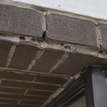
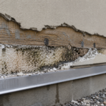
A mid-rise mixed-use project in coastal South Carolina, three years post-occupancy: the owner reports persistent interior condensation at storefront sill frames and the glazing contractor assumes gasket failure. When the glazier pulls the first lite, the thermal break polyurethane bond line is visibly delaminating and the aluminum extrusion on the interior leg shows white powdery oxidation consistent with accelerated galvanic activity.
Not a single gasket is compromised. The weep holes, specified at manufacturer minimum, are fully functional but physically incapable of draining the sill pocket under the wind-driven rain pressures the building routinely experiences.
This is not a product defect. It is a specification failure and it is repeating itself on projects across IECC Climate Zones 1 through 4 wherever coastal exposure meets minimum-code detailing.
How Thermally Broken Aluminum Storefront Sill Pockets Are Designed to Drain
The sill frame of a thermally broken aluminum storefront consists of an exterior leg, an interior leg, a thermal break channel connecting them (either a poured-and-debridged polyurethane section or a polyamide strut), a glazing pocket that captures the bottom edge of the insulating glass unit and weep holes drilled or punched through the exterior leg or end dams. The intended drainage path is straightforward: water that infiltrates past the exterior glazing gasket travels down into the sill pocket, migrates laterally along the sill extrusion toward the weep holes and exits to the exterior face of the assembly.
Manufacturer-specified weep hole sizing typically falls between 3/16 in. and 1/4 in.
diameter for circular holes or equivalent slot geometry, placed at 24 in. on center.
AAMA 501-15 provides general guidance on drainage design intent for storefront and curtain wall assemblies, treating weep holes as the primary active drainage element in the sill pocket. Most storefront systems are drained-only designs.
They are not pressure-equalized. That distinction matters enormously in practice because a drained-only system depends entirely on gravity to move water out, while a pressure-equalized design uses controlled air pressure to neutralize the driving force that pushes water inward.
Without pressure equalization, the weep hole is the sole line of defense.
What the design intent does not account for is the real-world installation environment. The sill pocket interior is not a clean laboratory channel.
In practice, it collects construction debris, mortar droppings, sealant squeeze-out from end dam installation and occasionally setting block fragments that shift during glazing. Any of these materials can partially or fully obstruct the weep hole opening or the lateral migration path along the sill extrusion floor.
A 3/16 in. diameter weep hole blocked by a 1/8 in.
mortar fragment loses more than 40 percent of its cross-sectional flow area. When the system is already operating at minimum specified capacity, that reduction is not recoverable through the remaining open holes at 24 in.
spacing. The design intent assumes a clean, unobstructed drainage path.
Field conditions routinely produce something different and the specification provides no tolerance for that gap.
The sill extrusion profile geometry also varies significantly between manufacturers and even between product lines within a single manufacturer’s catalog. Some profiles include a positive-slope floor in the glazing pocket that directs water toward the weep holes.
Others have a flat or slightly reverse-sloped pocket floor due to extrusion die tolerances or installation out-of-level conditions. A sill installed 1/8 in.
out of level across a 10-ft. bay can create a low point at the center of the bay rather than at the weep hole locations, pooling water exactly where drainage is slowest.
Specifiers who rely on manufacturer minimum weep hole requirements without reviewing the sill extrusion profile geometry and specifying installation level tolerances are accepting a drainage system that may not function as intended even before wind pressure enters the equation.
What AAMA Performance Testing Actually Measures and What It Misses
AAMA 101-19 performance classification ratings (R, LC, CW and AW) require water infiltration testing at static and dynamic pressures scaled to the performance class, but none of those tests evaluate sustained sill pocket drainage capacity under continuous wind-driven rain loading. ASTM E331-00 (2016) applies uniform static air pressure across the full frame assembly and measures whether water appears on the interior surface.
ASTM E547-00 (2016) runs the same evaluation under cyclic pressure. Both protocols define pass/fail solely by interior water appearance.
No current AAMA or ASTM protocol requires measurement of residual water volume retained in the sill pocket after the test concludes. A system can accumulate standing water throughout the entire test duration, drain slowly after pressure is released, show no interior water appearance and receive a passing classification.
The test was never designed to answer the question of how much water the sill pocket holds under load. It was designed to answer whether water crosses the interior plane.
Those are different questions entirely. Specifiers who treat an AAMA 101-19 CW or AW classification as confirmation that sill pocket drainage is adequate are misreading what the test certifies.
The test pressure durations compound this misreading. ASTM E331 applies water at a rate of 5 gallons per hour per square foot of test specimen area for 15 minutes at the specified test pressure.
That 15-minute window does not represent a coastal storm event. A sustained wind-driven rain episode on a South Carolina or Gulf Coast project can deliver continuous loading for two to four hours at pressures that meet or exceed the AAMA CW test threshold.
The sill pocket drainage system that holds adequately for 15 minutes of laboratory spray may be completely overwhelmed by the second hour of a real storm. No test protocol currently in use requires the specifier or manufacturer to answer what happens during that second hour.
The gap between ASTM E547 cyclic testing and field conditions is similarly instructive. E547 runs five cycles of pressure application and release, with each cycle lasting five minutes at pressure and one minute at zero pressure.
The pressure release intervals allow partial drainage between cycles. A real wind event does not provide one-minute drainage intervals.
Pressure at the glazing face fluctuates with gusting, but it does not drop to zero for 60 seconds at regular intervals during a storm. The cyclic protocol was designed to evaluate dynamic structural response and fatigue behavior, not drainage system performance under sustained load.
Using it as a proxy for drainage adequacy conflates two entirely different performance questions. AAMA 501.1-17 dynamic water infiltration testing using a calibrated aircraft propeller test apparatus better approximates the turbulent, sustained pressure conditions of field wind-driven rain, but it is not a standard requirement in most project specifications for storefront applications and adds cost to the mock-up testing program that owners and contractors routinely resist.
The Physics of Weep Hole Failure Under Wind-Driven Rain Pressure Differentials
Wind-driven rain creates a positive exterior pressure at the glazing face that partially or fully counteracts the gravity-driven drainage head at the weep hole. At sufficient wind speed, the weep hole stops functioning as an outlet and begins admitting water.
The orifice flow equation Q = Cd x A x sqrt(2gh) governs drainage capacity, where h is the gravity head from the water column depth in the sill pocket. A 1/2 in.
water column in the sill pocket generates a head pressure of approximately 0.026 psf. That is the entire driving force available to push water through the weep hole.
Compare that to real-world loading. ASCE 7-22 Chapter 30 component and cladding wind pressure calculations for a low-rise building in a 90 mph basic wind speed zone routinely produce 10 psf or more at the glazing face.
The exterior pressure overwhelms the gravity head by two orders of magnitude. Drainage stops.
Water accumulates.
Weep hole orientation compounds the problem in ways that specifications rarely acknowledge. Holes drilled through the exterior face of the sill extrusion are directly exposed to the full wind pressure differential.
Slots cut through the bottom of the exterior leg or through the end dam perform differently because their geometry partially shelters the opening from direct wind impingement, but these configurations are inconsistently detailed across projects and rarely coordinated between the storefront manufacturer’s shop drawings and the contract documents. Spacing at 24 in.
on center means a 10-ft. storefront bay has five weep holes serving the full sill pocket volume.
When two or three are partially obstructed by sealant migration, mortar droppings or debris during construction, the remaining openings cannot compensate.
The pressure differential problem is not limited to hurricane-prone coastal zones. A building in IECC Climate Zone 4 in the Pacific Northwest, designed to ASCE 7-22 with a 110 mph basic wind speed, produces component and cladding pressures at corner zones that exceed 20 psf on the glazing face.
The gravity drainage head in the sill pocket at any realistic water accumulation depth is still less than 0.05 psf. The ratio of wind pressure to drainage head at that exposure is roughly 400 to 1. The weep hole is not a drainage device under those conditions.
It is a water inlet. Specifiers working in high-wind zones outside the coastal Southeast need to recognize that the physics of weep hole failure apply equally to any project where sustained wind pressures at the glazing face exceed the trivial gravity head available to drive drainage.
That is most commercial storefront applications in exposed locations, regardless of climate zone or proximity to the coast.
AAMA 501.1-17 provides a dynamic pressure test method that better approximates field conditions than ASTM E331, but it is not routinely required in project specifications for standard storefront applications. Requiring it at the mock-up stage, with a defined pass criterion for sill pocket water retention depth, would give the project team actual performance data on the drainage system before the building is enclosed.
The cost of adding that requirement to the mock-up testing program is a fraction of the cost of investigating and remediating a compromised thermal break bond line three years after occupancy.
Why Trapped Water Targets the Thermal Break Bond Line Specifically
Pour-and-debridge polyurethane thermal break systems rely on both mechanical and adhesive bond between the cured urethane and the aluminum extrusion walls of the break channel. Polyamide strut systems rely on a crimped mechanical interlock.
Both are vulnerable to sustained moisture at the interface, but through different mechanisms.
The electrochemical mechanism is the one that produces the most visible and structurally consequential damage. Standing water in the sill pocket creates a galvanic cell between the aluminum extrusion and any dissimilar metal fasteners, anchors or embedded components in the assembly.
The thermal break interrupts the aluminum’s electrical continuity. This creates isolated anode and cathode zones that concentrate corrosion activity at the bond line rather than distributing it across the full frame length.
The result is accelerated pitting exactly where the thermal break meets the aluminum channel wall, which is the last place you want localized material loss.
Polyurethane hydrolysis compounds the structural degradation. Prolonged water contact degrades the urethane polymer chain through hydrolysis, reducing bond strength and allowing the thermal break to delaminate from the aluminum channel walls.
This is a chemical degradation mechanism entirely separate from mechanical fatigue or UV exposure. AAMA 505-17 thermal break structural testing does not evaluate hydrolytic degradation under sustained moisture exposure.
The test measures structural performance of the thermal break under load at ambient conditions. It says nothing about what happens to bond strength after three years of standing water contact in a coastal sill pocket.
The rate of hydrolytic degradation is temperature-dependent, which means sill pockets in Climate Zones 1 and 2 experience faster bond line deterioration than identical assemblies in cooler climates. A sill pocket in coastal Florida or Texas that maintains water contact at ambient temperatures of 80 degrees Fahrenheit or above accelerates the hydrolysis reaction compared to the same assembly in a Pacific Northwest project where sill pocket temperatures during rain events may be 20 to 30 degrees lower.
This temperature sensitivity is not reflected in any current specification requirement or manufacturer warranty condition. Manufacturers warrant the thermal break assembly against defects in materials and workmanship under normal conditions.
Sustained standing water in the sill pocket is not a condition the warranty language anticipates and it is not a condition the manufacturer’s installation instructions are designed to prevent. The specifier owns that gap.
Coastal and high-humidity climates in IECC Climate Zones 1 and 2 amplify both mechanisms. Chloride ions in coastal environments accelerate pitting corrosion of the aluminum oxide layer adjacent to the bond line and the combination of elevated humidity and salt deposition keeps the galvanic cell active even when the sill pocket appears visually dry between rain events.
A sill pocket that drains completely after each storm but retains a chloride salt film on the aluminum and polyurethane surfaces maintains electrochemical activity during dry periods. The corrosion mechanism does not require continuous standing water once chloride contamination is established.
This is why projects three to five miles from the ocean, outside the zone where direct salt spray is a recognized design concern, still show accelerated bond line degradation when sill pocket drainage is inadequate. The chloride transport mechanism operates through wind-carried aerosols at distances well beyond the visible surf zone and the sill pocket provides a collection geometry that concentrates the deposit.
Where Specifications Consistently Fail to Close the Gap
The specification-to-field gap on storefront sill drainage is not subtle. Section 08 44 13 of most project specifications references manufacturer minimum weep hole requirements without establishing a performance-based drainage criterion.
The specifier defers to the manufacturer. The manufacturer publishes minimums sized to pass ASTM E331 under laboratory conditions.
Nobody in that chain has accounted for the 10 psf wind pressure differential the building will experience on its worst exposure face.
Glazing contractors follow the shop drawings, which reflect manufacturer minimums. Field installers sometimes seal weep holes inadvertently during sealant application at end dams and that condition is rarely caught during inspection because the weep holes are small and partially obscured by the sill frame geometry.
By the time the building is occupied, the sill pocket drainage system is already compromised on some percentage of bays and no one has a baseline inspection record to identify which ones.
The shop drawing review process is where the drainage specification gap most often becomes permanent. A specifier who has written a performance-based drainage requirement into Section 08 44 13 but does not verify that the submitted shop drawings reflect that requirement during review has effectively waived the specification.
Shop drawings for storefront systems typically show weep hole locations schematically, often as a note referencing manufacturer standard details rather than as dimensioned, project-specific geometry. A reviewer who approves that submittal without confirming that the weep hole size, spacing and orientation match the specification requirement has closed the loop on paper while leaving the field condition unresolved.
The glazing contractor then installs to the manufacturer standard detail, which meets the minimum and the performance requirement disappears from the project without anyone making a deliberate decision to remove it.
Inspection at the time of installation is the last practical opportunity to catch drainage deficiencies before the building is enclosed. Most project specifications require special inspection of glazing systems for structural anchorage and water infiltration testing at completion, but they do not require inspection of weep hole geometry, spacing and freedom from obstruction during installation.
A special inspector present during storefront installation who is specifically tasked with verifying weep hole condition before end dams are sealed and sealant is applied can identify obstructed or mislocated holes while correction is still straightforward. That inspection task costs less than two hours of inspector time per floor of storefront.
The remediation cost for a compromised thermal break bond line, including investigation, frame replacement and interior finish repair, routinely exceeds $50,000 per affected bay on mid-rise commercial projects. The inspection investment is not a close call.
The thermal control layer in a thermally broken storefront depends on the integrity of the thermal break bond line. When that bond line degrades, the effective R-value of the assembly drops, condensation potential at the interior leg increases and the visible symptoms (condensation, oxidation staining) appear years after the underlying drainage failure began.
Owners and glaziers chase the symptoms while the root cause continues.
Detailing Strategies That Actually Address the Drainage Mechanics
Oversizing weep holes beyond manufacturer minimums is the simplest intervention and the one most resistant to contractor pushback. Specifying 3/8 in.
diameter holes at 12 in. on center on wind-exposed facades increases drainage cross-sectional area by approximately 2.5 times the manufacturer minimum configuration and reduces the spacing-related redundancy problem.
This costs nothing in materials and requires only a clear specification requirement in Section 08 44 13 with a note on the storefront detail drawings.
Weep hole orientation deserves equal attention. Specifying slots through the bottom of the exterior leg rather than holes through the face of the exterior leg reduces direct wind pressure exposure on the opening.
Some manufacturers offer sill extrusion profiles with bottom-exit weep geometry; specifying that profile explicitly rather than accepting any compliant product prevents substitution with face-drilled configurations.
End dam detailing at sill terminations is where most projects lose the most drainage capacity. End dams that are fully sealed to the rough opening prevent sill pocket drainage from exiting at the frame ends, which is often the highest-capacity drainage path available.
A weep slot through the end dam face, protected by a small drip cap or kick-out geometry, provides a drainage path that is partially sheltered from direct wind impingement.