- Shotcrete surfaces routinely fail the flatness, moisture and pH thresholds that air barrier manufacturers require for adhesion.
- No standard ACI 506 provision establishes facade-relevant flatness tolerances for shotcrete, leaving a critical specification gap.
- Podium transition zones concentrate moisture, carbonation and thermal bridging risks that compound adhesion failures at the air barrier plane.
- Shop drawing review runs on parallel structural and facade tracks where no single party owns the substrate-to-facade-ready transition.
- Remediation after delamination costs three to five times more than upfront substrate preparation specified and enforced before installation.
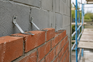
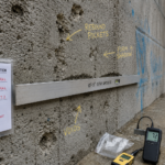
A building envelope consultant arrives at a podium-level facade mockup review on a mixed-use infill project and finds the fluid-applied air barrier delaminating from the shotcrete substrate in sheets, three weeks after application, before any cladding has been installed. The structural contractor has signed off on the wall as “complete,” but the surface profile reads like a topographic map, with rebound aggregate pockets, form shadow zones and moisture still wicking from the interior face.
No one in the project delivery chain had flagged that the air barrier manufacturer’s published substrate flatness tolerance, typically 1/8″ in 10 feet, was incompatible with what shotcrete routinely delivers. That failure was not a workmanship anomaly.
It was a predictable outcome of a specification gap that the industry has not adequately closed.
What Shotcrete Actually Delivers as a Substrate
Shotcrete is pneumatically applied concrete and the process itself generates surface variability that cast-in-place forming does not. Wet-process shotcrete pre-mixes water and cementitious material before delivery to the nozzle, producing a more consistent mix and lower rebound.
Dry-process shotcrete introduces water at the nozzle, which means mix consistency depends directly on nozzleman technique. Dry-process generates higher rebound rates, more surface porosity and greater aggregate segregation at the exposed face.
ACI 506R-16 Section 9 addresses finishing and curing but does not establish flatness tolerances relevant to facade attachment. Structural performance drives the specification.
The substrate that a facade contractor inherits is evaluated against compressive strength targets, not surface plane regularity. CMU and cast-in-place concrete substrates, which most air barrier and cladding specifications are written around, carry F-number tolerances and finishing requirements that produce predictable, workable planes.
Cast-in-place walls specified to ACI 117-10 Section 4.8 carry a standard tolerance of 3/8″ in 10 feet for formed surfaces, which is already at the outer edge of what many air barrier systems will accept. Shotcrete carries none of those expectations by default and no equivalent ACI 506 provision steps in to fill that gap for facade applications.
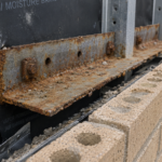
Rebound aggregate embeds in the surface or creates shadow voids behind reinforcing. Nozzleman angle variation produces overspray zones with inconsistent density.
A nozzleman working at an oblique angle to clear congested reinforcing, a common condition in podium retaining walls with closely spaced horizontal bars, produces a surface with alternating dense and porous zones that bear no relationship to the structural drawing. These conditions are localized, unpredictable and absent from any structural submittal the facade team will ever see.
The structural engineer reviewing the shotcrete submittal has no reason to document them and the facade contractor reviewing the air barrier submittal has no way to anticipate them from paper alone. The first time the surface variability becomes visible to the envelope team is when they walk the wall and by that point the schedule pressure to apply the air barrier is already present.
The Adhesion Assumption Gap in Air Barrier Specifications
Most fluid-applied air barrier specifications reference ASTM E2357-22 for assembly air leakage performance and defer to manufacturer data sheets for substrate preparation requirements. Those data sheets assume substrate flatness within 1/8″ in 10 feet, surface pH between 8 and 11 and moisture content at or below 19% by weight or passing the ASTM D4263 plastic sheet test.
Shotcrete surfaces in podium and below-grade conditions routinely fail all three criteria simultaneously.
The moisture threshold is the first failure point. Shotcrete placed against soil or within a podium slab system does not dry from both faces the way an above-grade CMU wall does.
Hydrostatic pressure, residual formwork moisture and ongoing capillary migration keep the substrate moisture condition elevated well past the point when a schedule-driven project is ready to apply the air control layer. Applying a fluid-applied membrane to a substrate that exceeds the manufacturer’s moisture limit produces a cohesive failure within the substrate surface layer, not an adhesive failure of the membrane itself.
That distinction is not semantic. A cohesive substrate failure voids the membrane warranty and shifts liability to the contractor who approved the substrate, but the specification rarely assigns that approval to a named party with authority to stop work.
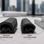
Surface pH compounds the moisture problem in ways that are not always visible. Freshly placed shotcrete carries a pH above 12 at the surface, which exceeds the upper threshold for some acrylic-based fluid-applied systems.
As the wall ages and carbonation progresses, pH drops. The window between “too alkaline for the membrane” and “too carbonated for adequate adhesion” can be narrow and it shifts depending on exposure conditions, mix design and the elapsed time between shotcrete placement and air barrier application.
A project where the shotcrete was placed in the fall and the air barrier is scheduled for early spring has a surface chemistry that no one on the project team has measured or documented.
Manufacturer substrate preparation requirements, including grinding high spots, priming and crack bridging at form ties and rebound voids, are rarely incorporated into the structural scope or the facade contractor’s bid. Some manufacturers require a cementitious skim coat over the entire shotcrete face before fluid-applied membrane application when surface porosity exceeds a defined threshold, a requirement that appears in the technical data sheet appendix and almost never in the project specification.
The scope gap is structural. No one owns the transition from “structurally complete shotcrete” to “facade-ready substrate,” and that gap is where assemblies fail.
Below-Grade and Podium Conditions That Amplify the Problem
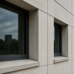
Podium-level shotcrete walls frequently serve dual roles: retaining wall below grade transitioning to facade backup above grade. The transition zone, typically within 18 to 36 inches of the podium slab elevation, is the highest-risk location on the entire assembly.
Below that line, the wall manages hydrostatic load. Above it, the wall is expected to accept a continuous air control layer and adhere cladding.
The substrate moisture condition at the air barrier plane is dynamic at that transition, not static at time of application. A wall that passes the ASTM D4263 plastic sheet test at 10 feet above the podium slab may fail the same test at 6 inches above it and the installer taping down plastic sheets in a congested transition zone between trades is unlikely to run that test at 6-inch increments.
Urban infill sequencing compounds this. Structure-first scheduling means shotcrete walls are frequently exposed to multiple weather cycles before the envelope design is even finalized, let alone before air barrier installation begins.
Surface carbonation progresses during that exposure period, dropping surface pH below the threshold required for adhesion of cementitious air barriers and some fluid-applied products. A pH below 8 at the surface is a documented adhesion risk for many membrane systems and it develops silently while the project schedule advances.
On a 24-month urban infill project where the shotcrete is placed in months 4 through 7 and the facade scope does not mobilize until month 14, the surface the air barrier installer encounters bears little chemical resemblance to the surface the structural contractor handed off. No submittal documents that change.
Thermal bridging at podium slab edges intersecting shotcrete backup walls creates a condensation risk at the air barrier plane that rarely appears in early energy models. ASHRAE 90.1-2022 continuous insulation requirements at podium transitions are frequently met on paper with nominal R-values that do not account for the effective R-value reduction caused by linear thermal bridges at slab edges.
A 2-inch polyisocyanurate board system with a nominal R-13 value loses a significant fraction of that thermal resistance at the slab edge and the resulting surface temperature at the air barrier plane can fall below the dew point of interior air during heating season. That condensation accumulates at the membrane-to-substrate interface and accelerates the same adhesion failure that moisture from the substrate side was already driving.
IBC 2021 Section 1805 governs foundation waterproofing and dampproofing at the below-grade condition but does not address the transition to above-grade facade performance. That regulatory gap mirrors the specification gap.
Adhered Cladding Systems and the Flatness Problem
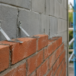
Adhered masonry veneer, thin-brick and large-format tile systems depend on full mortar contact between the setting bed and the cladding unit. ANSI A108.02 Section 4.
3. 8 requires a minimum of 95% mortar coverage for wet areas and exterior applications.
Shotcrete surface relief directly reduces achievable contact area before the installer ever opens a bag of mortar. A surface with 3/8″ amplitude variation across a 24-inch span cannot deliver 95% coverage with a standard notched trowel application.
The physics do not cooperate.
Large-format porcelain and stone panels, 600mm x 1200mm and larger, are particularly unforgiving. Substrate plane variation that falls within the visual tolerance of a smaller tile becomes a structural liability at large format.
Lippage exceeds acceptable limits. Hollow spots develop at the corners and edges where the setting material cannot bridge the gap between the panel back and the substrate plane.
Those hollow spots are not cosmetic deficiencies. They are load transfer failures waiting to manifest under thermal cycling, wind pressure cycling or seismic demand.
A 600mm x 1200mm porcelain panel with hollow spots at two corners is carrying its full dead load and any applied wind pressure through the two corners that do have contact. The setting material at those corners is seeing stress concentrations the system was never designed to carry and the failure mode under seismic demand is sudden and complete rather than progressive.
TCNA Handbook Method EJ171 specifies substrate deflection and flatness limits for exterior wall tile installations that shotcrete as-built conditions routinely violate without remediation. EJ171 requires the substrate to be plumb and true within 1/8″ in 10 feet, the same tolerance that fluid-applied air barrier manufacturers publish, which means the two systems share a flatness requirement that the substrate is independently failing to meet for each of them.
The compounding problem is this: a fluid-applied air barrier membrane applied over an irregular shotcrete substrate adds another layer of surface variability before the setting bed reaches the wall. Fluid-applied membranes bridge low spots and build up at high spots and the resulting surface is not the same plane as the shotcrete beneath it.
Most fluid-applied membranes are not evaluated as tile substrates under ANSI A118.12 bond strength protocols. The facade consultant reviewing the cladding submittal may never see the air barrier submittal and the air barrier installer may never see the cladding specification.
Each party reviews their own scope. No one reviews the stack.
Where Shop Drawing Review Breaks Down
Structural and facade scopes are submitted and reviewed on parallel tracks. The shotcrete contractor’s submittal goes to the structural engineer of record for compliance review.
Surface finish requirements for facade attachment are not a standard structural deliverable and the structural engineer has no obligation to evaluate the substrate against air barrier or cladding attachment criteria. That is not a criticism of structural engineers.
It is a description of how scope boundaries work.
The submittal review process reinforces those boundaries. A shotcrete submittal package typically includes mix design, aggregate gradation, compressive strength test data and nozzleman certification.
It does not include surface flatness measurements, pH readings or moisture content data, because none of those items appear in the structural specification section that governs the review. The structural engineer stamps the submittal as conforming to the structural documents, which it is.
The facade consultant, if one is retained during construction, reviews the air barrier and cladding submittals against the facade specification. Neither reviewer is looking at the same wall with the same criteria and neither submittal package contains the information the other reviewer would need to identify the conflict.
Pre-installation inspection requirements in air barrier and cladding specifications assign substrate verification to the installing contractor. Those requirements are written as obligations but enforced as suggestions.
The facade contractor arrives on site, looks at the wall and faces a choice between flagging a non-conforming substrate and delaying their own work or proceeding and hoping the system performs. Schedule pressure resolves that choice most of the time.
A facade contractor who flags a non-conforming shotcrete substrate on a podium project with a fixed cladding installation window is flagging a problem that will take weeks to remediate, during which their crew is standing by or demobilizing. The contractual obligation to inspect and accept the substrate before proceeding exists in the specification.
The economic incentive to proceed anyway exists in the project schedule. Those two forces are not evenly matched.
The three-party gap is structural to the delivery model. The structural engineer approves the shotcrete.
The facade consultant reviews cladding submittals. No specification section explicitly assigns responsibility for preparing the substrate to a facade-ready condition and no party is contractually required to verify the transition.
The RFI that should have been written before the air barrier went on the wall never gets written, because writing it requires someone to recognize the gap before the failure occurs.
The fix is not complicated. A pre-installation substrate inspection protocol, written into Division 07 and Division 09 specifications with explicit flatness, moisture and pH acceptance criteria, assigned to a named responsible party with stop-work authority, closes most of this gap before the first bucket of primer opens.
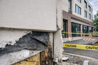
Remediation Realities and What They Actually Cost
When delamination occurs, the remediation scope is almost always larger than the initial failure area suggests. Sounding the substrate reveals hollow spots that extend well beyond the visually delaminated zone.
A 10-square-foot delamination visible at the surface frequently corresponds to 40 or 50 square feet of compromised bond when the full wall is sounded with a chain drag or hammer tap. That ratio is not unusual on shotcrete substrates where the surface porosity and moisture condition were borderline at the time of application, because the adhesion failure develops progressively from the weakest points outward rather than appearing uniformly across the non-conforming area all at once.
Grinding shotcrete to achieve flatness within 1/8″ in 10 feet is labor-intensive and generates significant dust and debris in an occupied or partially occupied building. Angle grinders with diamond cup wheels can remove high spots, but shotcrete surface hardness varies with mix consistency and rebound density, which means grinding rates are unpredictable and labor estimates based on square footage alone are unreliable.
A remediation scope estimated at three days of grinding can extend to two weeks when the crew encounters zones of particularly hard rebound aggregate or discovers that grinding one high spot reveals an adjacent void that requires filling before the surface plane is acceptable. Skim coat patching with cementitious underlayment can restore flatness but introduces a new bonding plane with its own adhesion requirements and cure time demands.
That skim coat must itself be tested for moisture content and surface pH before the air barrier re-application proceeds, adding another inspection cycle to a schedule that is already running behind.
Moisture remediation on an in-place podium wall is genuinely difficult. Crystalline waterproofing treatments applied to the positive face can reduce capillary transmission but do not eliminate hydrostatic pressure effects.
If the hydrostatic condition driving moisture into the wall face is not addressed at the source, a crystalline treatment slows the migration without stopping it and the moisture content at the air barrier plane continues to fluctuate seasonally. If the decision is made to re-apply the fluid-applied air barrier after remediation, the new application must meet the same substrate criteria the original application failed to meet.
That requires verification, not assumption.
The cost differential between proper substrate preparation specified and enforced before air barrier installation and reactive remediation after delamination is not marginal. Field experience across multiple podium projects puts remediation costs at three to five times the cost of upfront preparation when the full scope of sounding, grinding, patching, re-priming and re-application is tallied.
That ratio does not account for schedule delay, cladding removal if the failure is discovered after installation or warranty dispute costs. A fluid-applied air barrier manufacturer whose product failed due to a non-conforming substrate has a documented basis to deny the warranty claim and the resulting dispute over who owns the remediation cost adds legal and administrative expense on top of the direct construction cost.
The owner, who contracted for a performing building envelope, absorbs the schedule impact and the carrying cost of the delay regardless of how the liability dispute resolves.
Writing the Specification That Prevents the Failure
The shotcrete substrate problem is solvable at the specification stage, but only if the specification writer treats the interface as a distinct scope item rather than an assumption embedded in two separate sections. Division 03 should include a finish requirement for shotcrete surfaces that will receive air barriers or adhered cladding, with explicit flatness tolerances stated in the structural documents, not just the facade documents.
That requirement needs to appear where the shotcrete contractor will actually read it. A flatness tolerance buried in Division 07 Part 3 execution requirements is invisible to the shotcrete contractor who has already finished the wall and moved off site by the time the facade contractor mobilizes.
The Division 03 shotcrete section should also require the shotcrete contractor to document the as-built surface condition with a written report covering flatness measurements at defined grid intervals, surface pH readings and a photographic record of rebound pockets, form tie locations and any areas of visible segregation. That report becomes the baseline against which the pre-installation inspection is evaluated and it creates a record of the substrate condition at the time of structural completion that is separate from the condition at the time of air barrier application.
The gap between those two records, if one develops, is the evidence that documents what happened to the substrate during the intervening exposure period.
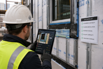
Division 07 air barrier sections should require a documented pre-installation inspection by the air barrier installer, with written substrate acceptance criteria covering flatness (1/8″ in 10 feet measured with a 10-foot straightedge), moisture content (passing ASTM D4263 or below 19% by weight), surface pH (between 8 and 11) and absence of rebound aggregate, form release compound and efflorescence. The inspection record should be a required submittal, not a field courtesy.
Tying the first payment application for the air barrier scope to receipt of the accepted substrate inspection record gives the general contractor a contractual mechanism to enforce the inspection without relying on the facade contractor’s voluntary compliance.
Division 09 tile and adhered cladding sections should cross-reference the Division 07 substrate acceptance criteria and require a second pre-installation inspection that confirms the air barrier surface, not just the shotcrete surface, meets the flatness and bond strength requirements for the cladding system being installed. That second inspection is the point where the full assembly stack is evaluated as a system rather than as a sequence of individual scope items.
The party with the most to lose when adhesion fails is the building owner and the party with the best position to prevent the failure is the envelope consultant reviewing the project during design. Specify the interface.
Name the responsible party. Require the inspection record.
The shotcrete will still be variable when it comes out of the nozzle. That is the nature of the process.
What changes is whether the project delivery chain is structured to catch that variability before it becomes a delamination failure three weeks before cladding installation.