ACM vs. Solid Aluminum vs. Steel Rainscreen Panels: A Specifier’s Guide to Fire Code Compliance and Long-Term Facade Performance in North America
Why the Code Landscape Shifted: and What Specifiers Are Now Accountable For
A project team specifies an ACM rainscreen assembly based on a manufacturer’s NFPA 285 test report, only to discover during third-party peer review that the tested assembly used 1.5-inch mineral wool cavity insulation while the project drawings call for 3-inch polyisocyanurate board. That deviation voids the tested assembly entirely.
The team is now six weeks from permit submission with a full re-specification on their hands.
This is not hypothetical. It reflects a pattern that has accelerated sharply since IBC 2021 tightened Section 1408 language around tested assembly documentation for exterior wall coverings on buildings exceeding 40 feet.
Prior code cycles permitted broader engineering judgment as a compliance pathway. IBC 2021 Section 1408.10 effectively closed that door for combustible cladding assemblies, requiring documented tested assembly records that match project conditions with specificity.
Grenfell Tower in 2017 was the global inflection point. The fire killed 72 people and traced directly to ACM panels with polyethylene cores.
Domestic incidents accelerated U. S.
code scrutiny at both the model code and jurisdiction levels. The liability exposure has shifted accordingly.
Specifiers who cannot produce a compliant tested assembly record now face increasing risk in litigation, professional liability insurance disputes and AHJ enforcement actions. NFPA 285, the Standard Fire Test Method for Evaluation of Fire Propagation Characteristics of Exterior Non-Load-Bearing Wall Assemblies, is the required test standard under IBC 2021 Section 1408.10.
1. Citing it without understanding what it actually tests is where most compliance failures begin.
What changed between IBC 2018 and IBC 2021 is not simply a tightening of language. The 2021 cycle introduced more explicit requirements around documentation specificity, narrowing the window for engineering judgment letters as standalone compliance instruments.
Several high-adoption jurisdictions, including California, New York and Illinois, had already moved in this direction through local amendments before the model code caught up. Specifiers working across multiple jurisdictions need to track not just the adopted IBC cycle but the local amendments layered on top of it.
A project in Chicago is not governed by the same enforcement posture as a project in Phoenix even when both jurisdictions have adopted IBC 2021. The professional liability dimension is equally real. Standard of care expectations for facade specifiers have shifted in response to the post-Grenfell environment.
Errors and omissions carriers are increasingly asking detailed questions about fire compliance documentation practices during policy renewals. Specifiers who cannot demonstrate a systematic process for verifying tested assembly match are carrying risk that their coverage may not fully address.
Understanding the Three Panel Types: Core Composition Is the Critical Variable
Metal panel is not a fire performance category. Treating it as one is the root cause of most compliance errors I see in specification review.
ACM panels consist of aluminum face skins bonded to a core material and that core is the entire fire performance story. Polyethylene cores are fully combustible.
Fire-retardant cores reduce flame spread but remain combustible and do not automatically satisfy any tested assembly requirement. Mineral-filled or A2-rated cores approach noncombustible classification and some manufacturers have obtained ASTM E136 compliance for specific A2-core products.
The distinction between product family and specific tested product matters here. A2 compliance for one panel thickness does not extend to another thickness in the same product line unless separately tested.
Solid aluminum panels are monolithic construction with no core. They are inherently noncombustible per ASTM E136, the Standard Test Method for Behavior of Materials in a Vertical Tube Furnace.
Thickness and alloy grade affect structural performance, deflection limits and attachment design, but neither variable affects fire classification. The panel itself does not trigger NFPA 285 compliance requirements.
Steel fabricated panels, whether cold-formed or brake-formed, are also noncombustible per ASTM E136 and per IBC 2021 Section 202’s definition of noncombustible material. Steel carries higher dead load and introduces greater thermal bridging risk at attachment points, but it shares the same fire classification pathway as solid aluminum.
Neither panel type eliminates the need for tested assembly documentation when combustible components appear elsewhere in the assembly. That distinction is critical and addressed in the compliance pathway section below.
The practical implication of core composition extends beyond fire classification into specification language. A specification section that calls for “ACM panels with fire-retardant core” without referencing a specific tested assembly configuration is an open invitation for substitution requests that may not be code-compliant.
Manufacturers of FR-core products will frequently submit compliance letters asserting NFPA 285 equivalence without providing the actual test report. The specification needs to require the test report as a submittal item, not a letter of compliance and it needs to identify the specific assembly configuration that the test report must match.
Locking this down in Division 07 and Division 08 language before the project goes to bid prevents the substitution problem from appearing during shop drawing review when schedule pressure is highest. The core composition variable also affects fabrication tolerances and panel flatness.
PE-core panels are more susceptible to oil-canning under thermal loading than mineral-filled core panels of equivalent thickness, which is a separate performance consideration from fire classification but one that affects long-term appearance and the integrity of panel edge seals.
NFPA 285: What the Test Actually Measures and What It Does Not
NFPA 285 measures one thing: fire propagation characteristics of an exterior non-load-bearing wall assembly under a specific test protocol. The test specimen is a two-story wall assembly.
Thermocouples measure temperature rise at defined points on the exterior face and within the wall cavity. The assembly passes or fails based on whether temperature limits at those measurement points are exceeded during the test duration.
What NFPA 285 does not evaluate is a longer list than most specifiers realize. It does not assess long-term weathering performance, wind-driven rain infiltration resistance, thermal cycling fatigue, freeze-thaw degradation of sealants or substrate materials or seismic racking.
Passing NFPA 285 tells you nothing about whether an assembly will manage the four control layers effectively over a 30-year service life. These are separate performance questions requiring separate documentation.
The tested assembly concept is where compliance failures concentrate. Every component in the tested wall must match the project assembly for the test data to carry code weight: panel type, core composition, insulation type and thickness, air barrier product and configuration, substrate material, fastener pattern and cavity depth.
Change the insulation from mineral wool to polyisocyanurate and you have a different assembly. Change the cavity depth from 1.5 inches to 3 inches and you have a different assembly.
Manufacturers structure their compliance documentation in three ways and specifiers must distinguish between them. A tested assembly report documents an actual NFPA 285 test of a specific assembly configuration.
A letter of compliance represents a manufacturer’s assertion that a product meets a standard, which is not the same as a tested assembly record. An engineering judgment letter extrapolates from tested data to a related but untested configuration.
Under IBC 2021 enforcement in most jurisdictions, only the tested assembly report carries full code weight. Engineering judgment letters are not recognized as equivalent documentation.
Request the actual test report, not a summary letter and compare it component by component against your project assembly before accepting it as compliant.
The test protocol itself has specific boundary conditions that specifiers rarely read in full. NFPA 285 uses a propane burner ignition source inside a room opening at the base of the two-story specimen.
The test runs for 30 minutes. Temperature limits are set at specific thermocouple locations on the exterior face and in the wall cavity above the fire floor.
The pass/fail criteria are defined in Section 8 of the standard. An assembly that passes does so under those specific conditions, with those specific components, at that specific geometry.
The test does not simulate a fully developed compartment fire, a fire originating within the wall cavity or fire exposure from an adjacent building. These are not criticisms of the test standard; they are scope limitations that specifiers need to understand when evaluating what the compliance documentation actually represents.
A tested assembly report is a necessary condition for code compliance on buildings over 40 feet with combustible cladding. It is not a complete fire safety evaluation of the facade system.
Comparing Fire Code Compliance Pathways for ACM, Solid Aluminum and Steel
The compliance pathway diverges significantly based on panel type and conflating these pathways creates real project risk.
Solid aluminum and steel panels are noncombustible per ASTM E136. On buildings over 40 feet, the panel itself does not trigger mandatory NFPA 285 compliance under IBC 2021 Section 1408. 10. This is where specifiers make a critical error in the other direction: assuming that a noncombustible panel face eliminates all NFPA 285 obligations.
It does not. If the assembly includes combustible components behind the panel face, including polyisocyanurate continuous insulation, a combustible air barrier membrane or a combustible weather-resistive barrier, the full assembly may still require NFPA 285 documentation depending on jurisdiction interpretation and AHJ enforcement position.
Verify this with your AHJ before finalizing the assembly.
ACM with PE or standard FR cores is a combustible cladding system. NFPA 285 compliance is mandatory for buildings over 40 feet regardless of jurisdiction.
FR cores do not pass by default. They must appear in a tested assembly that matches your project configuration.
This is non-negotiable under IBC 2021 Section 1408.10. 1.
ACM with A2 or mineral-filled cores occupies a different position. Some products have achieved ASTM E136 noncombustible classification, which can simplify the compliance pathway.
Verify the specific product and thickness, not the product category. Manufacturer literature frequently presents A2 classification at the product family level when the actual ASTM E136 data applies only to specific configurations.
ASTM E84 surface burning characteristics data appears frequently in manufacturer submittals and is not a substitute for NFPA 285 on buildings over 40 feet. IBC does not accept ASTM E84 as equivalent for exterior wall assembly compliance in this context.
Some AHJs also recognize FM 4880 as an alternative test pathway; confirm this acceptance in writing before committing to that documentation route.
The 40-foot threshold in IBC 2021 Section 1408.10 is measured to the highest occupied floor, not to the top of the parapet or the top of the cladding. This distinction matters on projects where the top occupied floor is below 40 feet but the parapet or mechanical penthouse cladding extends above it.
Some AHJs apply the Section 1408.10 requirements to the full height of the cladding regardless of occupied floor elevation; others apply it only to the portion above the threshold. Getting a written position from the AHJ on how they measure the 40-foot threshold before design development ends is not optional on projects near that boundary.
The cost of a tested assembly documentation requirement discovered at permit submission is measured in weeks of schedule delay and potential re-specification costs that dwarf the cost of a pre-design AHJ meeting. For projects in jurisdictions that have adopted local amendments beyond IBC 2021, the threshold height may be lower.
New York City’s Local Law 26 and subsequent amendments have imposed requirements that go beyond the model code in several respects. California’s Title 24 amendments similarly layer additional requirements on top of IBC.
Specifiers working in these jurisdictions need current, jurisdiction-specific code research, not model code assumptions.
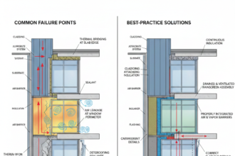
Cavity Firestopping: The Detail Most Specifications Get Wrong
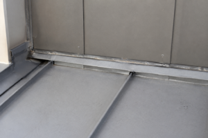
Passing NFPA 285 at the assembly level does not resolve firestopping requirements at floor lines. IBC 2021 Section 1408.10 and Section 715 require fire barriers at each floor level in combustible cladding assemblies on buildings over 40 feet.
This means mineral wool or intumescent firestop material packed continuously at each floor line, closing the rainscreen cavity against vertical fire travel.
The specification-to-field gap at this detail is significant. I have reviewed dozens of projects where the NFPA 285 report was in order but the firestop detail at the shelf angle was either missing from the drawings or drawn incorrectly.
A 1-inch gap left open at the floor line for drainage defeats the firestop. The tested assembly included a specific firestop configuration; the field detail must replicate it.
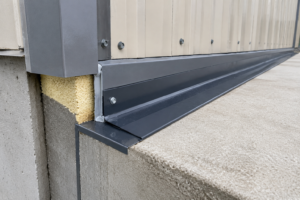
Shelf angles introduce a compounding problem. The shelf angle is a linear thermal bridge that interrupts continuous insulation and it is also the location where the firestop must be installed.
Getting both the thermal performance and the fire continuity right at the same detail requires coordination between the structural engineer, facade consultant and firestop manufacturer. Effective R-value calculations for the assembly must account for the thermal bridge at the shelf angle; nominal R-value of the insulation board tells you nothing useful about actual assembly thermal performance at that location.
Drained and vented cavity configurations affect firestop detailing differently. A vented cavity with open joints at the top and bottom of each floor zone requires firestop closure at the floor line to prevent chimney effect during a fire event.
Confirm that your cavity configuration matches the configuration in the NFPA 285 test report, including whether the tested assembly had open or closed cavity conditions.
The field installation quality of cavity firestops is one of the most consistently underdocumented aspects of rainscreen construction. Special inspection requirements under IBC 2021 Chapter 17 apply to firestopping in certain occupancy and construction type combinations, but even where special inspection is required, the inspector’s access to the cavity firestop location is limited once cladding installation has progressed past that floor.
The practical answer is a documented pre-installation conference with the cladding contractor and firestop installer before work begins, combined with photographic documentation of each floor line firestop before the cavity is closed. This documentation serves both quality control and liability purposes.
Firestop product selection also requires attention to the tested assembly. Intumescent products and mineral wool products are not interchangeable in a tested assembly context.
The NFPA 285 test report will identify the firestop product or product category used in the tested configuration. Substituting a different firestop product, even one with equivalent fire ratings in other test contexts, requires either a new tested assembly or manufacturer documentation confirming compatibility with the specific assembly configuration.
This is another area where engineering judgment letters circulate freely and carry less code weight than the documentation they are meant to replace.
Long-Term Facade Performance: Where Material Tradeoffs Actually Live
Fire code compliance gets the attention, but long-term facade performance is where material selection tradeoffs have the most practical consequence over a building’s service life.
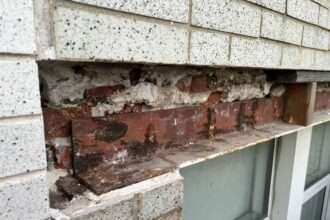
ACM panels with PE or FR cores are susceptible to core delamination under sustained thermal cycling, particularly at panel edges where the core is exposed or inadequately sealed. This is a moisture intrusion pathway as well as a structural concern.
A2-core ACM panels are generally more dimensionally stable under thermal cycling but carry a cost premium. Solid aluminum panels eliminate the core delamination failure mode entirely but require careful attention to panel thickness and stiffener design to control deflection at larger panel sizes.
Steel panels are the heaviest option and introduce the highest thermal bridging risk at attachment points. In IECC Climate Zones 5 through 7, the effective R-value penalty from steel attachment brackets can be significant enough to affect energy code compliance under ASHRAE 90.1-2022 continuous insulation requirements.
Aluminum brackets perform better thermally but require careful design at high wind load conditions. Neither material eliminates thermal bridging; the design goal is minimizing it through bracket geometry and insulation continuity.
Water control layer continuity behind any rainscreen panel system depends on the air barrier and WRB configuration, not the panel face material. All three panel types function as a rain screen, not a waterproof barrier.
The drainage plane is behind the panel. Specifiers who treat the panel face as the primary water control layer will see moisture intrusion failures regardless of panel material selection.
Coating system selection is a long-term performance variable that receives less attention than fire compliance but drives more warranty claims over a 20-year service life. PVDF coatings applied to a 70 percent resin formulation per AAMA 2605 are the standard for exterior architectural applications and carry a 10-year finish warranty from most major coaters.
Polyester coatings applied to AAMA 2604 standards carry shorter warranty periods and show measurably higher chalking and fading rates in accelerated weathering tests. The cost difference between AAMA 2604 and AAMA 2605 coatings is real but small relative to total installed cost; specifying AAMA 2605 as a minimum and requiring coater certification documentation in the submittal package is standard practice on projects where long-term appearance retention matters.
For steel panels, the coating system must also address corrosion resistance at cut edges and fastener penetrations. Zinc-rich primers and appropriate edge treatments are not optional details on steel panel systems in coastal or high-humidity environments.
Aluminum does not carry the same corrosion risk at cut edges, but anodized finishes on solid aluminum panels require attention to alloy selection; not all aluminum alloys anodize to the same color consistency and mixed alloy sourcing within a single project can produce visible color variation in the finished facade. Panel joint design affects long-term water management performance independently of panel material.
Open-joint rainscreen systems rely on pressure equalization and drainage to manage water that enters the cavity.