
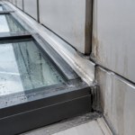

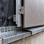
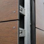

- Whole-building blower door tests consistently trace excess air leakage to the unowned gap at curtainwall-to-opaque wall sill conditions.
- Neither the curtainwall nor the opaque wall manufacturer designs their system to bridge the transition zone between assemblies.
- Unmodeled shelf angle thermal bridges increase effective U-values at transition zones by 40 to 70 percent above nominal assembly values.
- Remediating air barrier failures after enclosure costs 10 to 25 times more than addressing the transition membrane during construction.
- Correct detailing requires named trade responsibility, explicit installation sequencing and verified material compatibility before the receptor is set.
A 14-story mixed-use tower in the mid-Atlantic region fails its whole-building blower door test at 60% above the project’s target air leakage rate. The curtainwall contractor points to the masonry subcontractor.
The masonry subcontractor points back. The envelope commissioning agent finds the gap in 11 minutes with a smoke pencil: at every sill condition on every floor.
The transition detail had been drawn at 1/4-inch scale on the construction documents, referenced two different manufacturer’s installation guides and specified a fluid-applied membrane that neither trade had been told they were responsible for installing. Nobody owned the gap.
Nobody ever does.
Why the Curtainwall-to-Opaque Wall Joint Is the Envelope’s Weakest Link
The transition zone is a specific physical condition: the space between the curtainwall system’s outermost anchor or receptor and the adjacent opaque wall’s air barrier plane, typically 2 to 6 inches of unowned, undetailed and unwarranted space. Neither system manufacturer designed their product to bridge it.
Neither subcontractor’s scope of work explicitly covers it. And yet it is the location where the building’s four control layers must hand off continuously from one assembly to another.
The systemic problem is structural. Curtainwall systems are designed, specified and warranted as complete assemblies.
Rainscreen and masonry cavity wall assemblies are designed, specified and warranted as separate complete assemblies. No single manufacturer holds responsibility for what happens where they meet.
When a project’s specifications are written by separate consultants for each system, the gap between them often appears in the construction documents as a note reading “coordinate with adjacent trades” or as a detail that terminates at each system’s edge without bridging them.
ASHRAE 90.1-2022 Section 5. 4.
3. 1 requires a continuous air barrier across the full building enclosure with no exemption for system interfaces.
The code does not care that two different subcontractors are involved. The building either passes or it fails.
In my experience, mixed-facade commercial buildings fail this requirement at this specific location more consistently than at any other condition in the enclosure.
What makes this failure mode particularly persistent is that it survives multiple layers of project oversight without being caught. The curtainwall shop drawings show a complete, code-compliant system that terminates correctly at its own boundary.
The masonry or rainscreen submittals show the same. The architect reviews both sets of submittals independently and approves both.
Nobody reviews the interface between them because no submittal addresses it. The RFI process does not surface it because no subcontractor has a contractual reason to ask the question.
The gap clears every quality control checkpoint on the project and gets built into the wall on every floor, at every bay, without a single person flagging it as incomplete. That is not a coordination failure in the ordinary sense.
It is a structural deficiency in how mixed-facade envelope systems are procured and documented.
The four control layers that must transfer across this joint are the air barrier, the water-resistive barrier, the thermal control layer and the vapor control layer. Each has different material requirements, different lap and termination requirements and different tolerance for discontinuity.
The air barrier is the least forgiving: a gap of 1/16 inch running continuously across a building face produces measurable whole-building leakage. The water-resistive barrier is the most visible when it fails, because water staining and interior damage eventually appear.
The thermal layer is the most underestimated, because its failure is invisible and shows up only in energy bills and comfort complaints. All four must be addressed at the same physical location, in the same detail, by a trade that has been told it owns the work.
How Air Barrier Planes Diverge at the Sill and Jamb Conditions
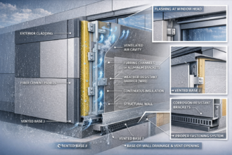
In a typical stick-built or unitized curtainwall system, the air barrier plane lives at the IGU perimeter seal, the pressure plate gasket and the back-pan or spandrel infill panel. None of these elements extend beyond the curtainwall frame.
The system is internally coherent and air-tight within its own boundary. The problem is that its boundary stops at the receptor.
In a typical rainscreen or masonry cavity wall assembly, the air barrier plane lives on the face of the structural sheathing or backup wall: either a fluid-applied membrane or a self-adhered sheet product. That membrane terminates at the rough opening or at the edge of the structural backup.
It has nowhere to go from there.
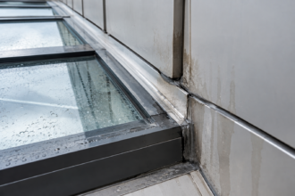
At the sill condition, the curtainwall receptor typically sits on a structural slab edge or shelf angle. The opaque wall’s air barrier membrane terminates 2 to 4 inches away with no transition material bridging the two planes.
Air moves freely through that gap regardless of how well either system performs in isolation. AAMA 501.2 field water infiltration testing at curtainwall perimeters has long served as a proxy indicator for air barrier failures at these conditions: if water can find a path under test pressure, air is already moving through the same gap under normal stack-effect pressure differentials.
The jamb condition is equally problematic and less frequently detailed correctly. The curtainwall vertical mullion and the opaque wall’s rough opening edge are rarely in the same plane.
The stepped geometry of that transition creates a condition that fluid-applied membranes cannot bridge without a backer rod, a cant or a rigid substrate to support them. Without that substrate, the membrane bridges air and eventually fails in tension.
The physics of stack-effect pressure make this failure worse on tall buildings than the gap geometry alone would suggest. In a 14-story building in a mixed heating-cooling climate, the pressure differential across the building enclosure at the lower floors in winter can reach 0.10 to 0.
15 inches of water column under normal operating conditions, without any mechanical system contribution. At that pressure, a 1/8-inch gap in the air barrier plane does not leak slowly.
It leaks at a rate that is measurable with a handheld flow meter. The curtainwall system itself, tested to AAMA 501.1 at 6.
24 psf, holds that pressure without measurable leakage. The 3-inch gap at the sill receptor, untreated, does not.
Field observation across multiple commissioning investigations confirms a consistent pattern: the air barrier membrane on the opaque wall sheathing is installed correctly and terminates cleanly at the rough opening edge. The curtainwall receptor is set correctly and sealed internally per the manufacturer’s instructions.
The gap between them, typically 2 to 4 inches of exposed slab edge or shelf angle flange, receives no treatment at all. In some cases, a bead of sealant is applied at the visible interior edge of the receptor as a cosmetic measure, which does nothing to address the air barrier plane discontinuity at the exterior face of the backup wall.
That sealant bead is the field equivalent of the note on the drawing that says “coordinate with adjacent trades. ” It acknowledges the problem without solving it.
What Whole-Building Blower Door Testing Is Actually Finding
Envelope commissioning practice across commercial building types consistently identifies curtainwall-to-opaque wall transitions as a top-three air leakage source, alongside penetrations and mechanical equipment curbs. This is not a marginal finding.
It shows up in deficiency reports with enough frequency that experienced commissioning agents now prioritize these conditions in their smoke-pencil survey before they look anywhere else.
The sensitivity of the failure is worth stating directly. A 1/16-inch continuous gap running the full height of a curtainwall bay contributes air leakage equivalent to leaving a standard door open several inches.
Multiply that by 40 bays on a 14-story building and the blower door result is not surprising. It is predictable.
The failure is hard to find without pressurization because the gap is concealed. The curtainwall receptor covers it from the exterior.
The opaque wall cladding covers it from the other side. Interior finishes cover it from inside.
Visual inspection finds nothing. Only ASTM E779 or ASTM E1827 whole-building pressurization testing with simultaneous smoke visualization actually locates the leakage path.
IECC 2021 Section C402.5.1.2 requires air barrier continuity documentation, but field verification methods vary significantly by jurisdiction. Many AHJs do not require blower door testing on commercial projects.
The result is that buildings with chronic air leakage at this condition pass plan review, pass inspection and fail their occupants for the life of the building.
The remediation cost calculus is what makes pre-construction attention to this detail economically non-negotiable. Addressing the transition membrane during construction, before the receptor is set and before cladding is installed, costs roughly $8 to $15 per linear foot of transition depending on material selection and site conditions.
Addressing the same condition after the building is enclosed, with cladding removal, receptor disassembly, membrane installation and reassembly, costs $150 to $400 per linear foot in documented remediation projects. The ratio is not unusual in building enclosure work, but the magnitude is.
A 14-story building with 40 curtainwall bays averaging 10 feet in width has approximately 1,600 linear feet of sill transition alone, not counting jambs. The difference between getting it right during construction and remediating it after occupancy is a number that gets the attention of ownership groups in ways that technical arguments about air barrier continuity do not.
ASTM E779 testing protocol requires depressurizing and pressurizing the building to 75 Pa and measuring steady-state airflow at each pressure increment. The resulting curve produces a whole-building air leakage rate normalized to building enclosure area, expressed in CFM75 per square foot.
ASHRAE 90.1-2022 sets a maximum of 0. 40 CFM75 per square foot for commercial buildings.
Projects with unaddressed curtainwall-to-opaque wall transitions routinely test at 0.55 to 0. 75 CFM75 per square foot, with the excess leakage tracing directly to the transition condition during simultaneous smoke visualization.
The test does not lie about where the air is going. The smoke pencil confirms what the numbers already indicate.
The Thermal Bridging Problem the Energy Model Didn’t Capture
Energy models assign a U-value to the curtainwall assembly and a separate U-value to the opaque wall assembly. The interface between them receives no thermal bridge penalty.
This is not a conservative assumption. It is an error.
The specific bridge is the structural steel shelf angle or embed plate that supports the curtainwall at each floor line. That element passes through the opaque wall’s insulation layer and connects the interior-conditioned structure to the exterior cladding.
It is a textbook linear thermal bridge: high-conductivity steel spanning across the thermal control layer. ISO 10211 methodology for thermal bridge calculation captures this condition explicitly through 2D finite element analysis.
THERM 7.x, the standard 2D simulation tool for fenestration and envelope assemblies, can model it accurately. Most energy models do not use either.
The quantitative impact is significant. Research published through the Building Enclosure Council and peer-reviewed THERM studies indicates that unmodeled shelf angle thermal bridges can increase the effective U-value at the transition zone by 40 to 70% above the nominal assembly U-value.
ASHRAE 90.1-2022 Normative Appendix A now includes linear thermal transmittance (psi-value) requirements that address exactly this condition, but adoption in practice lags the code language.
The compounding effect is where the real performance gap opens. When the air barrier also fails at this location, convective heat loss adds directly to conductive loss.
The actual thermal performance of the transition zone can be two to three times worse than the energy model predicts. The model shows compliance.
The building loses heat at a rate the model never anticipated.
The shelf angle geometry determines the severity of the bridge and the range of conditions found in practice is wide. A 6-inch by 4-inch by 3/8-inch steel angle running continuously across a building face at each floor line, with no thermal break, produces a linear thermal transmittance (psi-value) in the range of 0.25 to 0.
40 W/m-K depending on the insulation thickness and configuration of the adjacent wall assembly. On a building with 10-foot floor-to-floor heights and 200 linear feet of shelf angle per floor across 14 floors, that unmodeled bridge represents a meaningful annual energy penalty that the energy model never accounts for and the energy code compliance path never penalizes.
The thermal break solution is commercially available and well-documented. Proprietary thermal break assemblies from manufacturers including Schock, Halfen and others provide load-rated connections between the structural slab and the shelf angle with a polyamide or similar low-conductivity element interrupting the steel-to-steel conductive path.
These systems reduce the psi-value at the shelf angle condition by 60 to 80% in THERM analysis. They add cost, typically $25 to $45 per linear foot installed and they require coordination between the structural engineer of record and the curtainwall engineer because the thermal break element affects the load path and the deflection characteristics of the connection.
That coordination rarely happens unless the specification explicitly requires it and the structural drawings show the thermal break as a required element rather than an optional upgrade. When the specification is silent and the structural drawings show a standard weld plate, the thermal break does not get installed.
The energy model does not notice. The building performs accordingly.
What the Sill Condition Actually Requires: Material by Material
The correct material sequence at the sill starts with the structural backup: slab edge or shelf angle. A thermal break material comes next, separating the steel from the curtainwall receptor and interrupting the conductive path.
Then the curtainwall receptor. Then the transition membrane, which must lap from the opaque wall’s air barrier membrane onto the back of the receptor or onto a rigid substrate that connects to it continuously.
The transition membrane requirements are specific and non-negotiable. The bridging material must be chemically compatible with both the curtainwall system’s frame coating or finish and the opaque wall’s air barrier membrane.
Fluid-applied membranes require a minimum substrate width and a primed, clean surface to achieve rated adhesion. They cannot bridge gaps wider than their product data sheet allows without a backer.
Self-adhered sheet membranes require the same substrate conditions and must be lapped and sealed at all terminations.
The sequencing of trades is where this fails in the field. The fluid-applied membrane on the opaque wall sheathing must be installed and cured before the curtainwall receptor is set, so the transition lap can be made correctly.
On most projects, the curtainwall is set first because the structural frame drives the schedule. The membrane subcontractor arrives later and finds the receptor already in place, blocking access to the substrate.
The transition gets improvised or skipped.
Specifying the correct material is necessary but not sufficient. The specification must assign responsibility to a named trade, define the sequence of installation explicitly and require inspection at the transition before the receptor is covered by cladding or interior finish.
Without those three elements in the contract documents, the detail on the drawing is aspirational.
Chemical compatibility between the transition membrane and adjacent materials is a failure point that receives almost no attention in specifications and produces failures that are difficult to diagnose after the fact. Fluid-applied polyurethane membranes are incompatible with certain silicone-based curtainwall sealants: the silicone can inhibit cure at the interface and produce a permanently tacky, non-adhered bond line that looks correct on visual inspection and fails under the first thermal movement cycle.
Butyl-based self-adhered sheet membranes can delaminate from aluminum curtainwall frames if the frame surface is not primed with a compatible primer and many curtainwall manufacturers’ installation guides explicitly prohibit direct membrane adhesion to their frame coatings without written approval. The specification needs to name the specific membrane product, the specific primer and the specific curtainwall frame coating and require written compatibility confirmation from both manufacturers before installation begins.
That level of specificity is rare. The result is that field crews select compatible-looking products based on what is available on the jobsite and what the membrane manufacturer’s technical representative recommends without knowledge of the curtainwall system’s specific finish chemistry.
The minimum lap dimension at the transition is another specification gap. Most fluid-applied membrane manufacturers require a minimum 2-inch lap onto an adjacent substrate to achieve rated adhesion and continuity.
At the sill condition, achieving a 2-inch lap onto the back of the curtainwall receptor requires that the receptor be positioned with enough clearance from the face of the sheathing to allow the membrane to wrap around the receptor flange. That clearance dimension needs to appear on the structural drawings, the curtainwall shop drawings and the air barrier installation drawings simultaneously.
On most projects, it appears on none of them.
The Jamb Condition Requires a Different Solution Than the Sill
The sill and the jamb look like the same problem on a section drawing. They are not.
At the sill, the transition is primarily planar: two membranes at roughly the same elevation need to connect across a gap. At the jamb, the transition involves a change in plane, a change in substrate material and often a change in the depth of the air barrier relative to the face of the building.
The curtainwall vertical mullion sits proud of or recessed from the opaque wall face depending on the system geometry. The opaque wall’s air barrier membrane wraps the rough opening edge and terminates.
The mullion’s perimeter seal addresses the glazing unit but does not extend to the rough opening. The gap between them is three-dimensional and cannot be solved with a single membrane layer applied in a single direction.
The correct approach at the jamb uses a preformed transition piece: either a rigid cant or a factory-fabricated membrane boot




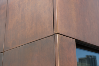


The detailing gaps highlighted in your article can lead to significant moisture intrusion issues. During our client inspections, we frequently discover that these transitions are often overlooked, resulting in costly damage. When we use moisture meters and thermal imaging, we can pinpoint concealed leaks that may not be obvious. What strategies do you recommend for addressing these gaps during the initial design phase to prevent future complications?