- Zinc scuppers on North American facades are failing prematurely due to unaddressed galvanic couples with steel angles, aluminum rivets and copper components.
- European manufacturer details assume masonry substrates and mild climates that do not match North American steel-stud construction or de-icing salt exposure.
- The three most dangerous metal pairings are zinc against galvanized steel, aluminum fasteners and copper or copper-ion-bearing drainage streams.
- Facade transition geometry concentrates moisture dwell time and dissimilar metal contact exactly where corrosion risk is highest.
- Specifiers can prevent failure by requiring dielectric isolation, Type 316 stainless fasteners with neoprene washers and a copper audit of the full drainage path.
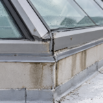
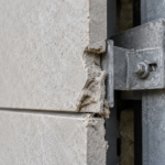
Eighteen months after substantial completion on a six-story mixed-use project in Chicago, a facade engineer pulled back the base cladding panel at a zinc scupper assembly and found white-streaking stains, active pitting and a zinc flange that had lost nearly 40 percent of its original thickness. The project specifier had cited a 25-year warranty from the European manufacturer’s literature.
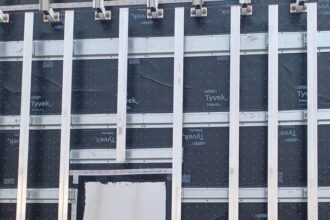
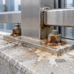
The investigation revealed two simultaneous galvanic couples operating at the same connection: the zinc scupper was bearing directly against a galvanized steel backup angle and the assembly was secured with aluminum blind rivets through the zinc flange. Neither contact condition was flagged in the original detail.
Both were fatal to the assembly’s longevity.
This is not an isolated case. It is the predictable outcome of specifying zinc drainage components without accounting for the substrate and fastener conditions that North American commercial construction introduces by default.
Why Zinc Is Appearing at More North American Facade Transitions
Zinc has earned genuine specification momentum on mid-rise commercial facades over the past decade. The aesthetic demand for pre-weathered and natural patina finishes is real and European manufacturers have responded by expanding North American distribution networks aggressively, bringing product literature calibrated to Central European installation conventions along with their material.
The problem is a category confusion that runs through most specifications. Specifiers who understand zinc as a cladding panel material carry those panel-system assumptions directly into scupper and gutter detailing without scrutiny.
Zinc panel systems are engineered at the manufacturer level with compatible clips, isolators and fasteners. Zinc drainage components, by contrast, land in a specification section where the detailer is assembling a custom condition from multiple trades and multiple material families.
The panel system’s engineered compatibility disappears the moment the drainage component leaves the manufacturer’s catalog and enters a field-assembled connection.
ASTM B69, the Standard Specification for Rolled Zinc, is the baseline North American product standard for the material itself. The European equivalent, EN 988, carries different alloy tolerances that affect corrosion behavior in ways that matter at connection points.
Titanium-zinc alloys conforming to EN 988 typically contain 0.06 to 0. 20 percent titanium and 0.08 to 1.
0 percent copper, with copper content at the upper range producing measurably different galvanic behavior than the leaner alloys common in ASTM B69 material. Neither standard governs installation.
That gap is where failures originate.
Zinc’s long-term performance reputation in Europe is legitimate. That reputation rests on substrate conditions, climate variables and installation conventions that do not automatically transfer to a steel-stud backup wall in IECC Climate Zone 5. When a specifier pulls a zinc scupper detail from a European manufacturer’s technical manual and drops it into a project drawing set without adapting the substrate and fastener conditions, the warranty language travels but the performance conditions do not.
How Galvanic Corrosion Works at Metal-to-Metal Interfaces
Zinc sits at approximately negative 0.76 volts on the standard hydrogen electrode scale. That position makes zinc anodic relative to steel and aluminum in most electrolyte conditions, which is exactly why galvanized coatings work: the zinc sacrifices itself to protect the steel substrate.
At a facade transition, that same electrochemical logic operates against the zinc drainage component when it contacts a more cathodic metal.
ASTM G82, the Standard Guide for Development and Use of a Galvanic Series for Predicting Galvanic Corrosion Performance, provides the reference framework. Three variables govern couple severity: the electrode potential difference between the two metals, the surface area ratio of anode to cathode and the electrolyte conductivity of the moisture present.
De-icing salt runoff in Climate Zones 4 through 6 dramatically increases electrolyte conductivity relative to clean rainwater. Sodium chloride concentrations measured in snowmelt runoff at base-of-wall conditions in Chicago, Minneapolis and Buffalo regularly exceed 500 parts per million during peak winter maintenance periods.
That single variable accelerates corrosion rates far beyond what European testing protocols anticipate and no European manufacturer’s accelerated weathering test replicates it.
Facade transitions concentrate all three risk factors simultaneously. Water accumulates at base-of-wall and parapet conditions by design.
Dwell time is extended because drainage geometry is rarely perfect and capillary forces hold moisture at lapped interfaces. Dissimilar metals are most densely co-located at these exact junctions because that is where the drainage component, the backup structure, the cladding attachment and the air barrier termination all converge.
The distinction between wet galvanic corrosion and atmospheric galvanic corrosion matters here. Standing water contact drives the faster reaction.
Condensation film drives a slower but continuous reaction. Both are active at facade transitions.
Neither stops when the rain stops. A zinc scupper that drains completely after each rain event still experiences continuous atmospheric galvanic corrosion at every metal-to-metal contact point through the condensation film that forms on cold metal surfaces during temperature cycling.
In Climate Zone 5, that cycling occurs on nearly every day between October and April.
The Three Most Dangerous Metal Pairings at Zinc Gutter Assemblies
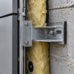
The zinc scupper bearing against a galvanized steel backup angle is the most common dangerous pairing in steel-stud backup wall construction. Galvanizing is a zinc coating over steel; it is not a neutral substrate.
Once the galvanic coating at the contact point is consumed, the base steel becomes cathodic and the zinc scupper becomes the sacrificial anode. The pitting accelerates because the cathode area (the steel angle) is large relative to the localized anode area at the contact point.
This is exactly the area ratio geometry that ASTM G82 identifies as the most aggressive configuration. A galvanized shelf angle running the full length of a building elevation presents an enormous cathode surface.
The zinc scupper flange bearing against it at a single scupper location presents a small anode. The current density at that small anode is correspondingly high and the material loss rate reflects it.
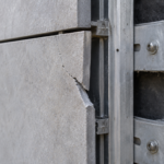
The second pairing is zinc gutter against aluminum cladding attachment hardware, specifically blind aluminum rivets used to secure zinc gutter flanges to backup structure. Aluminum is cathodic to zinc in the presence of chloride-bearing moisture.
ASTM G71, the Standard Guide for Conducting and Evaluating Galvanic Corrosion Tests in Electrolytes, documents published galvanic potential data showing the aluminum-to-zinc differential under chloride exposure. The small anode (zinc flange material at the rivet hole) paired with the large cathode (aluminum rivet body) creates the worst possible area ratio.
Pitting initiates at the fastener penetration and propagates outward. In the Chicago project, rivet holes that were 4.8 millimeters in diameter at installation had corroded to irregular voids exceeding 12 millimeters in diameter at 18 months.
The flange perforations had compromised the assembly’s water control function entirely before the exterior cladding panel was removed.
The third pairing is zinc scupper against copper flashing or copper-bearing solder. Copper sits approximately 0.85 volts more cathodic than zinc.
Even trace copper ion runoff from upstream copper components dissolves into the drainage stream and deposits cathodic copper ions onto the zinc surface downstream, creating a distributed galvanic attack that is nearly impossible to detect until pitting is well advanced. A copper through-wall flashing at a lintel three floors above a zinc base scupper can deliver sufficient copper ion concentration to the drainage stream to initiate pitting at the zinc surface.
The source and the failure location are separated by enough distance that the connection is rarely made during investigation.
One field substitution compounds all three scenarios: stainless steel fasteners are routinely substituted as a perceived upgrade. Stainless is strongly cathodic to zinc.
A stainless screw through a zinc flange creates a large cathodic surface area relative to the zinc material at the penetration. Best practice requires stainless fasteners with neoprene-isolated zinc washers at every penetration.
Most field crews omit the washer. The washer is a small-diameter component that arrives in a bag, gets set aside during installation and is absent from the finished assembly.
Specification language that requires the washer without requiring photographic documentation of installed washers before concealment produces the same outcome as specification language that omits the washer entirely.
European Detailing Assumptions That Do Not Transfer to North American Conditions
European zinc gutter tradition developed against masonry and concrete backup substrates. There are no embedded steel angles, no galvanized shelf angles and no steel-stud framing at the drainage termination zone in a traditional European masonry facade.
North American light-frame and steel-stud construction introduces dissimilar metals at the drainage termination by default, before a single fastener is selected. A zinc scupper set into a masonry opening in a load-bearing brick wall contacts brick, mortar and possibly a stone sill.
None of those materials appear on the galvanic series. The corrosion risk profile of that assembly is categorically different from a zinc scupper bearing against a galvanized steel shelf angle in a steel-stud rainscreen wall and European manufacturer literature was written for the former condition.
The climate baseline difference is equally significant. European zinc performance data reflects moderate humidity, low chloride exposure in inland regions and minimal freeze-thaw cycling relative to the Great Lakes, Upper Midwest and Northeast markets where zinc specification is growing fastest in North America.
De-icing salt splash at base-of-wall conditions is a North American variable absent from most European product testing protocols. A zinc scupper performing for 40 years on a Munich commercial building has never experienced the electrolyte conductivity of chloride-laden snowmelt runoff pooling at its base flange in January.
Munich averages fewer than 30 freeze-thaw cycles annually. Chicago averages more than 100. Each freeze-thaw cycle pumps moisture into the metal-to-metal interface and mechanically works the contact zone, maintaining the electrolyte film that drives galvanic corrosion continuously through the heating season.
Manufacturer installation guides specify copper or stainless fasteners for zinc-to-zinc connections. They do not explicitly address mixed-substrate conditions common in North American commercial construction.
That silence is not permission. It is a gap that the specifier must fill.
DIN 18339, the German standard for zinc sheet and strip work, governs installation practice in the European context. No parallel North American standard exists.
SMACNA’s Architectural Sheet Metal Manual, 7th Edition, Chapter 1 provides general dissimilar metals guidance but does not address architectural zinc drainage components specifically. The specifier writing a zinc scupper detail on a North American project has no domestic code anchor for connection requirements.
That absence forces reliance on manufacturer guidance that was not written for the substrate conditions the detail will encounter. The practical consequence is that the specifier’s detail becomes the governing document for the assembly and the specifier’s awareness of galvanic risk becomes the primary line of defense against the failure mode that the manufacturer’s literature does not address.
How Facade Transition Geometry Concentrates Corrosion Risk
The wall base condition is the highest-risk location in any zinc drainage assembly. The zinc scupper or through-wall gutter sits at the intersection of the drainage plane, the air barrier termination and the cladding base angle.
Metal-to-metal contact density is at its maximum. Moisture dwell time is at its maximum.
The water control layer terminates here, which means any failure in the drainage component directly compromises the assembly’s ability to manage the water control layer. Base-of-wall conditions also collect the full drainage contribution of the wall above, concentrating whatever dissolved ions, particulates and contaminants the drainage stream has accumulated across the full facade height.
A zinc scupper at grade level on a six-story building receives drainage that has passed across every metal component on the wall above it.
At the parapet condition, the geometry creates a different but equally dangerous concentration. Zinc cap flashing or coping bears against the parapet wall framing, typically galvanized steel in light-frame construction.
The top surface collects precipitation and directs it toward the scupper. The underside of the coping is a condensation surface in cold climates.
Both faces of the zinc component are in contact with moisture simultaneously and the backup structure is almost always galvanized steel. Parapet cap flashing details frequently show the zinc coping sitting directly on a galvanized steel top track without any isolation layer called out.
That contact condition runs the full length of the parapet, producing a continuous galvanic couple along the entire bearing line rather than a localized contact at a single fastener.
Thermal movement compounds the geometry problem. Zinc has a coefficient of thermal expansion of approximately 22 millionths per degree Celsius, roughly twice that of steel.
At facade transitions where zinc bears against steel backup structure, differential movement opens and closes the interface joint cyclically. Each cycle pumps moisture into the contact zone and expels it.
The electrolyte never fully dries at the interface. Galvanic corrosion operates continuously.
On a 3-meter zinc scupper assembly spanning between two fixed points, the differential thermal movement between the zinc component and the steel backup structure across a 50-degree Celsius seasonal temperature range produces approximately 1.6 millimeters of relative displacement. That movement is sufficient to abrade any protective oxide layer that forms at the contact surface, continuously exposing fresh metal to the electrolyte.
The drainage geometry itself can trap water at the zinc surface. Scupper throats that are undersized for the roof drainage area or that lack adequate slope to the drain, create ponding conditions directly against the zinc assembly.
SMACNA recommends a minimum scupper throat depth of 75 millimeters for most commercial applications, but field-fabricated scuppers are routinely installed shallower to accommodate cladding reveal dimensions. This is a design error compounded by a material error.
Ponding water against a zinc component in a galvanic couple is not a slow failure. It is a rapid one.
Specifying Zinc Drainage Components Without Repeating This Failure
The Chicago project failure was preventable at the specification stage. Three specific measures would have changed the outcome.
First, require dielectric isolation at every zinc-to-dissimilar-metal bearing condition. EPDM or neoprene isolation tape at the zinc scupper bearing against the backup angle breaks the galvanic circuit.
This is not a complex detail. It requires a line in the specification and a note on the drawing.
Most current zinc scupper details include neither. The isolation tape should be specified at a minimum thickness of 1.5 millimeters and should extend beyond the bearing surface by at least 25 millimeters in each direction to account for installation tolerance.
A tape that stops at the edge of the bearing surface leaves exposed zinc in contact with the steel angle at the perimeter of the bearing zone, which is exactly where moisture accumulates by capillary action.
Second, prohibit aluminum fasteners in zinc drainage assemblies by specification. Require stainless steel Type 316 fasteners with neoprene-isolated zinc washers at every penetration.
Reference ASTM G82 in the specification section as the basis for the fastener compatibility requirement. That citation gives the contractor and the shop drawing reviewer a technical basis for rejecting substitutions.
Type 316 stainless is specified rather than Type 304 because the molybdenum content in 316 provides measurably better resistance to pitting in chloride environments. The potential difference between 316 stainless and zinc is still significant, which is why the neoprene washer isolation is not optional.
Require the contractor to submit photographic documentation of installed washers at each fastener location before the assembly is concealed by cladding panels. That requirement converts the washer from a specification item that disappears in the field into a documented installation step.
Third, audit the upstream drainage path for copper components before finalizing the zinc drainage detail. If copper is present anywhere in the roof drainage system that discharges to or across the zinc assembly, either eliminate the copper, substitute a compatible metal or introduce a physical separation that prevents copper ion contamination of the drainage stream.
This audit should be performed at the design development stage, not during construction administration. Copper through-wall flashings, copper conductor heads and copper-soldered joints in roof drainage leaders are common enough in commercial construction that their presence should be assumed until the drainage path is specifically reviewed and documented as copper-free.
Zinc performs. It performs for decades when the assembly is detailed to isolate it from incompatible metals.
The European track record is real. Replicating it in North American commercial construction requires acknowledging that the substrate conditions are different and detailing accordingly.
The warranty language from the manufacturer’s literature does not change the electrochemistry. The galvanic series does not have a warranty exception.