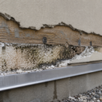
- A 22-story tower suffered panel delamination after anchor capacities tested 34% below manufacturer-published values.
- Stone honeycomb panels transfer load through multiple bond interfaces that solid stone fastener standards never anticipated.
- Four distinct failure modes including adhesive bond line failure and fatigue-driven pull-through are rarely captured by standard lab testing.
- Manufacturer anchor tables rely on small sample sizes tested under dry lab conditions that do not reflect winter field exposure.
- Facade engineers must specify independent field pull-out testing with moisture conditioning and statistically defensible acceptance criteria.
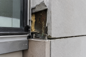
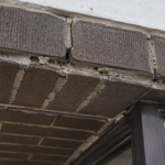
During a post-installation inspection on a 22-story mixed-use tower in the mid-Atlantic region, a facade engineer discovered that six stone honeycomb panels had partially delaminated at their upper screw-fixed anchor points after a single winter season, despite the installer following the manufacturer’s published torque specifications. Pull-out testing on adjacent panels revealed actual anchor capacities averaging 34% below the manufacturer’s tabulated values.
The discrepancy traced directly to the interaction between the aluminum honeycomb core, the thin stone face and substrate moisture infiltration. No project specification had required independent pull-out verification testing under field-representataive conditions.
That gap is not unusual. It is the norm.
What Makes Stone Honeycomb Panels Structurally Different from Solid Stone
Stone honeycomb panels are composites: a thin stone face, typically 5 to 8 mm thick, bonded to an aluminum honeycomb core, with total panel thickness running 20 to 30 mm. Solid stone cladding for comparable spans typically requires 30 to 40 mm minimum thickness.
The weight difference is significant. Stone honeycomb panels weigh 12 to 18 kg/m² versus 75 to 100 kg/m² for 30 mm solid granite, a reduction of 75 to 80%.
That weight savings is why specifiers are adopting them at an accelerating rate on projects where dead load limits drive material selection.
The load path is fundamentally different from solid stone. In solid stone, a fastener bears against a monolithic material with consistent mechanical properties through its full thickness.
In a honeycomb panel, load transfers from the fastener through the stone face, across the adhesive bond line and into the aluminum core before distributing to the subframe. Each of those interfaces represents a potential failure plane that simply does not exist in solid stone.
On a high-rise tower with hundreds of anchor points, the probability that at least one of those interfaces is compromised by installation variability, material inconsistency or moisture exposure is not theoretical. It is near-certain.
Core geometry matters more than most specifiers realize. Hexagonal cell size, cell wall thickness and aluminum alloy grade all govern local bearing capacity around fastener penetration points.
A panel using 3003-H19 aluminum with a 6 mm cell size and 0.05 mm wall thickness behaves very differently under fastener pull-out than one using 5052-H38 aluminum with a 10 mm cell size and 0. 08 mm wall thickness, even if both panels carry the same nominal thickness designation and the same stone face.
Those distinctions rarely appear in manufacturer marketing literature and are not always disclosed in the anchor tables specifiers rely on for design. Facade engineers need to request core specification sheets separately and verify that the tested configuration matches what is being supplied.
ASTM C1242, the standard guide for dimension stone attachment systems, was written primarily with solid stone in mind. It does not address composite panel core behavior.
Relying on it for honeycomb panel design is a category error. The standard’s guidance on embedment depth, edge distance and fastener spacing was developed against the mechanical properties of monolithic stone.
Applying those parameters to a 6 mm stone face bonded to an aluminum core produces anchor designs that appear code-compliant on paper while carrying failure modes the standard never anticipated.
How Screw-Fixed Anchors Are Typically Detailed in Honeycomb Panel Systems
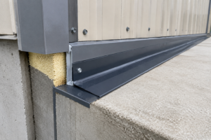
Three attachment configurations dominate the market: face-fixed screws through routed kerfs in the stone surface, edge-fixed clips bearing on the panel perimeter and back-pan systems with through-bolted connections. Each creates a different pull-out load path through the composite assembly and none of them behaves the way a fastener behaves in solid stone.
Face-fixed kerf anchors concentrate load at the stone surface and depend entirely on the adhesive bond line to transfer that load into the core. Edge-fixed clips distribute load more evenly across the panel perimeter but introduce peel stress at the bond line under wind suction.
Back-pan systems with through-bolted connections can bypass the stone face entirely, but they require precise panel fabrication tolerances that field conditions frequently violate.
Manufacturer-supplied anchor tables typically report characteristic pull-out values derived from laboratory coupon tests on pristine, dry, room-temperature panels. Those are not field conditions.
They are not even close to field conditions on a mid-Atlantic high-rise in February. A panel that has been stored outdoors on a pallet for six weeks before installation, exposed to rain and temperature swings, has a different adhesive bond condition than the specimen tested in a climate-controlled laboratory.
That difference is not captured in the table and it is not disclosed in the footnotes.
Screw engagement depth is constrained by panel thickness in a way that solid stone is not. With solid stone, an engineer can specify deeper embedment to increase pull-out capacity.
With a 25 mm honeycomb panel, the geometry is fixed. There is no additional depth available.
A specifier who recognizes that published pull-out values are marginal for the design wind load cannot simply call for longer screws and expect a proportional capacity increase. The only path to higher capacity is a different anchor configuration, a different panel product or a reduced anchor spacing, each of which carries its own cost and coordination implications.
Installer variability compounds the problem in both directions. Over-torquing screws in the thin stone face causes local crushing of honeycomb cells, reducing the effective bearing area and degrading capacity before the panel ever sees a wind load.
Under-torquing leaves panels susceptible to wind-induced vibration fatigue over time. Field observations on multiple projects have documented torque values ranging from 40% to 180% of the manufacturer’s specification within a single installation crew on the same project day, without any individual installer recognizing the deviation.
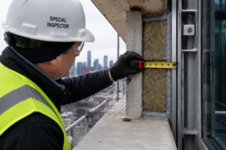
Specifying a torque value is necessary but not sufficient. Specifying a verification protocol, including periodic torque checks by a special inspector during installation, is what actually controls the outcome.
ETAG 034, the European Technical Approval Guideline for Kits for External Wall Claddings, Parts 1 and 2, is widely referenced by honeycomb panel manufacturers for CE-marked products. Its test protocols include cyclic load testing.
However, ETAG 034 is not adopted by the International Building Code and is not referenced in AAMA standards, which means North American specifiers are often working without an equivalent framework. A manufacturer whose product carries a CE mark under ETAG 034 has met a defined qualification threshold.
That same manufacturer selling into the North American market is operating in a qualification vacuum and the project team absorbs the difference.
The Pull-Out Failure Modes Specific to Composite Panel Construction
Four distinct failure modes occur in screw-fixed honeycomb panel assemblies. Understanding all four is necessary because they interact and because standard pull-out testing protocols often capture only one of them.
Mode 1 is stone face cone failure. The screw pulls a conical plug of stone face material and the failure surface is entirely within the thin veneer.
In solid stone with 25 to 50 mm embedment, cone geometry provides meaningful resistance. In a 5 to 8 mm face, the cone is so shallow that capacity is drastically reduced.
The honeycomb core provides no meaningful contribution to this failure mode. Limestone and marble faces, which are softer and more porous than granite, are particularly susceptible.
A 6 mm Crema Marfil face will exhibit cone failure at loads that a 6 mm absolute black granite face would carry without cracking, yet both may appear under the same generic anchor table if the manufacturer does not distinguish by stone type and grade.
Mode 2 is adhesive bond line failure. Load transfers from the stone face to the honeycomb core through structural adhesive.
Peel and shear stresses at the bond interface can cause progressive delamination before screw pull-out occurs. This mode is invisible during visual inspection.
It is not captured by standard pull-out testing unless the test fixture replicates the actual load angle at the anchor point, which field-installed geometry rarely matches the laboratory configuration. Bond line failure is particularly sensitive to moisture.
Epoxy adhesives used in panel fabrication can lose 20 to 40% of their shear strength after sustained moisture exposure at the bond interface, a condition that develops gradually and produces no visible warning before failure.
Mode 3 is core crushing and pull-through. The screw head or washer pulls through the honeycomb core as cell walls buckle locally.
Capacity here is governed by cell wall thickness and alloy grade, not by stone properties. Most specifiers are still referencing stone anchor tables.
That is the wrong table for this failure mode. Core crushing is also sensitive to the washer geometry specified.
A larger-diameter washer distributes load across more cell walls and increases pull-through resistance. That detail is rarely called out in project specifications and installers default to whatever hardware the manufacturer packages with the panel system.
Mode 4 is fatigue-driven progressive failure. Thermal cycling and wind-induced vibration create cyclic loading at anchor points.
Aluminum honeycomb cores are susceptible to fatigue crack initiation at cell wall junctions adjacent to fastener holes. Failure can occur at loads well below static pull-out capacity after sufficient cycles.
On a building in a high-wind exposure category, an anchor point may experience thousands of load cycles annually from wind gusts alone, before thermal cycling is added. AAMA 501.5, the test method for thermal cycling of exterior walls, applies to the assembly but does not specifically address fastener fatigue in composite panels.
Brookes and Meijs documented composite panel failure modes in European high-rise applications in the fourth edition of “Cladding of Buildings,” and the fatigue failure pattern they describe matches what field investigations in North America are now finding. The implication for design is that a static pull-out test result, even a conservative one, does not fully characterize the anchor’s service life performance.
Why Manufacturer Anchor Tables Are Insufficient for Design Reliance
The gap between manufacturer test conditions and field conditions is not a minor calibration issue. It is a systematic problem that produces unconservative designs.
Laboratory specimens are tested at controlled humidity and temperature. Field panels arrive on site after storage, handling and exposure.
Moisture infiltration behind the stone face degrades the structural adhesive bond before service loads are applied. Freeze-thaw cycling in IECC Climate Zones 5 through 7 accelerates that degradation.
The panel that performed acceptably in a laboratory coupon test at 70 degrees Fahrenheit and 50% relative humidity is not the panel being loaded by a January wind event in Philadelphia. A project in Climate Zone 6 with a design wind pressure of 50 psf at the upper corners of the building is applying loads to panels whose adhesive bond condition may already be compromised by a season of freeze-thaw exposure.
The manufacturer’s table was not built to account for that sequence of events.
Sample size is a second problem. Many published pull-out values derive from small coupon populations, n equals 5 to 10 specimens.
Characteristic values calculated from populations that small do not represent lower-bound field performance with any statistical confidence. A 5th-percentile value derived from 8 test specimens carries a confidence interval so wide that the actual lower-bound field capacity could fall substantially below the reported characteristic value without contradicting the test data.
ICC-ES AC193, the acceptance criteria for mechanical anchors in concrete elements, requires minimum test populations and statistical rigor that produce genuinely conservative characteristic values. Stone honeycomb panel anchors have no equivalent North American third-party qualification pathway.
Specifiers are relying on self-certified data.
Substrate variability introduces a third source of error. Manufacturer tables assume installation into a rigid, planar substrate.
Real subframing introduces tolerance stack-up, panel bow and differential thermal movement. Those conditions alter the effective load angle on the fastener, shifting the failure mode and reducing capacity in ways the manufacturer’s table does not account for.
A panel installed with a 3 mm shim under one corner to correct subframe tolerance is no longer loaded the way the test specimen was loaded. The load angle at the upper anchor changes, the peel component at the bond line increases and the failure mode shifts from Mode 3 toward Mode 2, which is the mode least likely to be captured by the manufacturer’s test protocol.
Third-party validation is rare and should be required. Unlike structural adhesive anchors governed by ICC-ES AC308 or AC193, stone honeycomb panel anchors have no equivalent qualification pathway in North America.
The absence of a standard does not make the risk disappear. It transfers it to the project team.
Facade engineers who accept manufacturer tables without independent verification are accepting liability for a data set they did not generate, cannot audit and cannot verify was produced under conditions representative of their project.
What Independent Field Pull-Out Testing Should Include
Specifying independent pull-out verification testing is the single most effective risk mitigation available to the facade engineer. The specification needs to define what that testing actually requires, because “pull-out testing per manufacturer recommendations” is not a sufficient requirement.
That language allows the manufacturer to define the test protocol, the acceptance criteria and the sample size, which reproduces exactly the same conflict of interest that produced the inadequate tables in the first place.
Testing should occur on panels installed on the actual subframing system, not on bench-mounted coupons. The substrate condition should replicate field installation, including any tolerance corrections, shim conditions and sealant or gasket compression.
Load should be applied at the actual angle the anchor experiences under combined wind suction and self-weight, not at a convenient perpendicular angle. On a typical high-rise facade, the upper anchor of a panel carries a combination of outward wind suction and downward gravity load from the panel self-weight.
That combined load vector is rarely the angle used in manufacturer coupon tests. Testing at the actual service angle is not a refinement.
It is a basic requirement for the result to mean anything.
The test program should include panels that have undergone controlled moisture exposure, because the mid-Atlantic failure case that opened this article traced directly to moisture infiltration. Testing only dry panels and then applying a generic reduction factor is not adequate engineering.
A controlled moisture conditioning protocol, such as immersion or cyclic wet-dry exposure for a defined period before testing, produces results that are directly applicable to the climate the building will actually experience. For projects in IECC Climate Zones 4 through 7, that conditioning step is not optional.
It is the only way to test the panel condition that will exist during the highest wind events of the year, which in those climate zones occur in winter when panels are at their wettest.
Sample size should follow a statistically defensible protocol. Using the framework of ICC-ES AC193 as a model, even if that standard does not formally apply, produces characteristic values with known confidence intervals.
A minimum of 20 anchor tests across representative panel locations, with statistical analysis to establish a 5th-percentile lower-bound value, is a defensible starting point. Tests should be distributed across corner panels, field panels and panels adjacent to penetrations, because those locations experience different installation conditions and different service loads.
The design value should then incorporate an appropriate safety factor applied to that lower-bound result, not to the manufacturer’s mean value. Applying a safety factor to a mean that was itself derived from a small, non-representative sample produces a design value that is conservative in appearance only.
The Specification Gap That Allows This Risk to Persist
The mid-Atlantic failure case was not the result of a negligent installer or a defective product. It was the result of a specification that trusted manufacturer data without requiring independent verification.
That is a procurement and specification problem, not a product problem.
Division 07 specifications for stone honeycomb cladding assemblies routinely incorporate manufacturer anchor tables by reference and call it structural adequacy. No project-specific pull-out testing.
No field verification protocol. No requirement to test under conditions representative of the actual climate exposure.
The specifier writes “install per manufacturer’s recommendations” and considers the anchor design complete. That language shifts all engineering judgment to the manufacturer, who has a commercial interest in publishing values that make their product competitive and who bears no direct liability when field performance falls short of tabulated values.
The IBC does not prohibit this approach. ASTM C1242 does not prohibit it either.
But neither standard provides a basis for confidence that the tabulated values will hold in the field. The absence of a prohibition is not engineering validation.
IBC Section 1604.3 requires that structural systems be designed with adequate stiffness to limit deflections and Section 1603. 1 requires that construction documents show the loads used in design.
Neither provision creates an affirmative obligation to verify that the anchor capacity assumed in design is actually achievable under field conditions. That gap in the code framework is real and it will not close until a failure produces litigation that establishes a duty of care standard through case law or until a standards body takes up the issue directly.
Facade engineers who are evaluating stone honeycomb panels for mid- to high-rise applications need to treat the anchor design as a project-specific engineering exercise, not a table look-up. That means engaging the manufacturer’s technical team to understand the statistical basis for published values, specifying independent field pull-out testing as a contract requirement and establishing a minimum tested capacity that includes a safety factor referenced to a documented lower-bound value rather than a mean.
It also means writing those requirements into the contract documents with enough specificity that a contractor cannot satisfy them by submitting a manufacturer’s data sheet and a certificate of compliance. The specification language has to describe the test protocol, the acceptance criteria, the sample size and the consequences of failing to meet the minimum tested capacity before installation proceeds.
What the Next Generation of Specifications Needs to Require
The industry’s adoption of stone honeycomb panels has outpaced the development of qualification standards for their anchor systems. That gap will produce more failures before it produces better standards.
The facade engineering community cannot wait for ICC-ES or AAMA to close it.
Project specifications for stone honeycomb cladding should require, at minimum: a documented statistical basis for all published anchor values including sample size and confidence interval; field pull-out testing on installed panels at a frequency of not less than one test per 500 square feet of cladding area; testing under moisture-conditioned panel conditions for projects in IECC Climate Zones 4 through 7; and a design safety factor applied to the 5th-percentile tested value rather than the manufacturer’s mean. Each of those requirements addresses a specific, documented failure mechanism.
The statistical basis requirement forces manufacturers to disclose the quality of their data. The field testing frequency requirement ensures that installation variability is captured across the full cladding area, not just at a few representative locations selected by the installer.
The moisture conditioning requirement aligns test conditions with the climate exposure that governs anchor demand. The safety factor requirement ensures that the margin between tested capacity and design load is calculated from a genuine lower-bound value.
Facade engineers writing these requirements for the first time will encounter resistance from contractors and manufacturers who argue that the requirements are burdensome, that no other project has required them and that the manufacturer’s published data is sufficient. All three of those arguments were available to the project team on the 22-story mid-Atlantic tower before the panels delaminated.
None of them prevented the failure. The specification language that allows this risk to persist is not a reasonable industry standard.
It is a habit that has not yet been tested in enough failure investigations to produce widespread change. Facade engineers who write better specifications now are not waiting for that process to run its course.
The weight savings that make stone honeycomb panels attractive are real. So is the pull-out risk.
Any specification that captures one without addressing the other is incomplete. The panels that partially delaminated on that 22-story tower were installed correctly.
The specification failed them.