- Demountable rainscreen systems are gaining traction due to embodied carbon mandates but lack North American performance standards specific to their unique risks.
- Repeated removal cycles degrade clip engagement depth and spring-lug preload in ways that standard single-cycle mock-up testing cannot detect.
- Field investigations consistently show 15 to 30 percent clip pull-out capacity reductions after two or more removal cycles compared to virgin installation values.
- Isolator pad displacement and sealant discontinuity at clip zones create compounding moisture intrusion pathways that only surface years after occupancy.
- Specifiers can manage these risks by requiring ten-cycle pull-out testing and post-cycling water penetration testing before system acceptance.
The Embodied Carbon Mandate Driving Specifiers Toward Demountable Systems
Adaptive reuse project volume has climbed steadily over the past decade and tenant-churn economics are pushing building owners to demand facade flexibility as a base specification requirement rather than an upgrade. That demand intersects directly with embodied carbon reduction targets: LEED v4.1 MRc Building Life-Cycle Impact Reduction credit language explicitly rewards design strategies that extend material service life and enable component reuse and the ILFI Living Building Challenge Materials Petal creates similar pressure toward envelope assemblies that can be disassembled and redirected at end of occupancy.
The result is a specifier market primed to accept demountable rainscreen systems on sustainability grounds before the structural and hygrothermal performance questions have been answered.
The problem is that North America has no performance standard specific to demountable rainscreen cladding. The closest applicable benchmark is European ETAG 034 Parts 1 and 2, which addresses cladding kits and includes provisions for mechanical resistance and water tightness, but carries no jurisdictional weight on this side of the Atlantic.
Manufacturer marketing language describing “circular economy” benefits and “tool-free removal” has outpaced independent third-party validation by a wide margin. Specifiers are writing demountable systems into project manuals based on product literature, not tested performance data.
The carbon accounting logic that drives this demand is not wrong on its face. A facade panel that can be removed, refurbished and reinstalled on a subsequent project genuinely reduces the embodied carbon burden compared to a panel that goes to landfill at first tenant changeover.
The Environmental Product Declaration data for aluminum composite panels, fiber cement and high-pressure laminate cladding all show that manufacturing represents 80 percent or more of total lifecycle carbon for those materials. Extending service life across two or three building occupancies cuts that manufacturing carbon by a proportional fraction.
The sustainability argument is arithmetically sound. The specification practice built on top of it is not, because the carbon benefit only materializes if the panel survives repeated removal cycles with its structural and water-resistance performance intact.
A panel that causes a moisture intrusion failure requiring full substrate replacement generates far more embodied carbon in remediation than it saved through reuse. The specifier community has not yet connected those two sides of the ledger with the same rigor it applies to the initial carbon calculation.
Clip, Carrier and Panel: Anatomy of a Demountable Rainscreen Interface
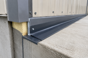
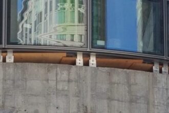
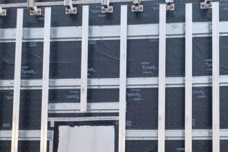
Three primary attachment typologies define the demountable rainscreen market. The sliding hook-and-rail system suspends panels from an extruded aluminum rail using a hooked return at the panel edge; demountability is achieved by lifting the panel up and out of the hook engagement.
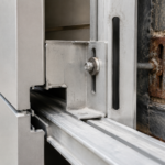
The snap-lock clip uses a spring-tension lug that deflects during insertion and springs back to capture the panel flange; removal requires a release tool or deliberate inward deflection of the lug. The mechanical fastener with captive nut system uses a threaded connection at the clip-to-carrier interface, with the nut retained in the carrier slot to allow panel removal without disassembling the substrate framing.
Each typology must transfer the same three load types through a connection designed to be repeatedly disengaged: gravity dead load from panel self-weight, out-of-plane wind pressure and suction and in-plane seismic racking. That load path runs through the clip engagement zone every time, regardless of how many removal cycles have occurred.
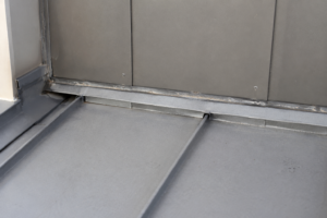
The weather-resistance challenge is distinct from the structural one. In a fixed system, the clip zone is sealed once during installation and left undisturbed for the building’s service life.
In a demountable system, that same zone is a recurring disruption point. Every removal cycle creates an opportunity to displace isolator pads, break sealant continuity and introduce dimensional variation that compounds over time.
AAMA 501.1 establishes a baseline water penetration test protocol using dynamic pressure, but it tests virgin installations. It does not address post-cycling performance, which is precisely where demountable systems diverge from fixed ones.
The “tolerance stack” problem compounds this: dimensional variation accumulates across repeated removal and reinstallation cycles, progressively degrading clip engagement depth and load-transfer efficiency in ways that no single-cycle mock-up test will reveal.
The hook-and-rail typology is the most common in the North American market and also the most susceptible to engagement depth loss over time. The nominal hook engagement depth on most extruded aluminum rail systems is between 12 and 18 millimeters.
Field measurement after two or more removal cycles on high-traffic panels, specifically corner panels and panels adjacent to mechanical access points, routinely shows engagement depths at the low end of that range or below it. The panel has not visibly moved, but the structural reserve has been consumed by dimensional drift.
A snap-lock system introduces a different failure sequence: the spring lug loses preload through repeated deflection and the audible click that field workers use as a confirmation of engagement becomes an unreliable indicator of actual capture force. Neither of these degradation patterns is visible during a standard pre-occupancy inspection.
Load Transfer at the Clip Interface: Where Structural Redundancy Goes Missing
Fixed rainscreen systems distribute load across continuous sub-framing with multiple fastener points per clip. A typical fixed aluminum rainscreen clip engages substrate framing at two or more fastener points and published ICC-ES ESR reports provide defined pull-out and shear values for those connections.
That data exists because fixed systems go through the ICC-ES AC428 acceptance criteria process, which requires structural testing, water penetration testing and durability evaluation as a package. Specifiers can pull an ESR number, verify the tested conditions match the project parameters and move forward with documented confidence.
Snap-lock demountable clips frequently rely on a single engagement lug with no published pull-out or shear capacity data. The manufacturer’s literature may cite an “allowable load” derived from internal testing, but that testing rarely replicates post-cycling conditions and the data is not third-party verified through ICC-ES or an equivalent body.
That is not a minor gap. That is a structural redundancy failure by design.
Wind uplift is the critical failure mode. ASCE 7-22 Chapter 30 establishes components and cladding wind pressure requirements based on building geometry, exposure category and risk category.
Corner zones routinely generate design pressures of 40 to 60 psf on mid-rise commercial buildings in Exposure Category C. Demountable clip manufacturers rarely provide system-specific tested data at those pressure levels and almost none provide data at those pressures after cyclic engagement and disengagement.
The cyclic fatigue dimension compounds the structural problem further. Repeated engagement and disengagement introduces micro-deformation in aluminum clip flanges.
The effective bearing area at the lug interface decreases with each cycle as the aluminum work-hardens and the engagement geometry shifts. No current North American standard requires cyclic fatigue testing for demountable facade clips.
Specifiers have no standardized data to evaluate, because the industry has not yet demanded it.
The seismic load path deserves equal attention, particularly on projects in SDC C and above. ASCE 7-22 Section 13.5 requires nonstructural components, including cladding and their attachments, to be designed for seismic forces derived from the component importance factor, the component amplification factor and the spectral response acceleration at the site.
For a mid-rise office building in a moderate seismic zone, that calculation can produce in-plane racking demands of 15 to 25 psf on individual panels. Fixed systems address this through continuous sub-framing that distributes racking across multiple clip lines.
Demountable systems with discrete clip points and no continuous engagement along the panel edge concentrate that racking demand at the clip lug, which is the same point already carrying gravity and wind loads. The structural engineer of record is responsible for verifying that the clip connection can handle the combined load case, but without post-cycling test data from the manufacturer, that verification is based on first-installation values that may not hold after the system has been exercised.
That is a calculation built on an assumption that the field condition will not support.
The Clip Interface as a Recurring Water Intrusion Pathway
Three failure mechanisms are specific to demountable systems and none of them appear in standard mock-up testing. First, the isolator or gasket at the clip seat compresses or displaces during reinstallation.
The EPDM pad that provided thermal break and drainage plane continuity in the original installation gets pinched or rolled out of position when a replacement panel is driven home by a worker who has never seen the original installation sequence. Second, sealant continuity at the drainage plane breaks when panels are removed and replaced without full re-sealing.
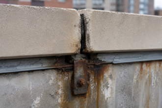
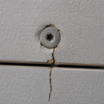
The original bead is disturbed, the replacement bead is applied inconsistently and the result is a discontinuous water control layer at the most vulnerable point in the assembly. Third, fastener holes in the carrier rail elongate over multiple removal cycles, creating an unintended capillary pathway that bypasses the drainage cavity entirely.
Standard mock-up testing does not catch any of this. ASTM E1105 static pressure water infiltration testing and AAMA 501.2 field water testing are both performed on virgin, never-removed installations.
They test the system as designed, not the system as it performs after three tenant changeovers. That distinction matters enormously on adaptive reuse projects where the demountability feature is exercised repeatedly over a 20-year ownership horizon.
The drainage plane discontinuity risk deserves specific attention. Demountable systems frequently use segmented WRB or eliminate the WRB entirely behind the clip zone, relying on the rainscreen cavity for drainage.
ASTM E2112, which addresses WRB continuity principles for fenestration installation, provides a useful analogy: discontinuities in the water control layer at penetration points are where failures concentrate. The same principle applies at clip zones.
When clip geometry creates horizontal ledges that interrupt downward drainage, water ponds at those ledges and migrates laterally to the first discontinuity it finds. The “reinstallation gap” compounds this: field observation across multiple failure investigations confirms that replacement panels are routinely installed by trades unfamiliar with the original sequence, introducing misalignment that defeats the designed drainage geometry before the first rain event.
The EPDM isolator displacement problem is more common than the industry acknowledges. Most demountable clip systems ship with isolator pads pre-positioned on the clip body, held in place by friction or a shallow recess.
That positioning survives first installation under controlled conditions with experienced applicators. It does not reliably survive the second or third installation by a general contractor’s punch-list crew working from a one-page installation diagram.
The pad migrates, the clip body contacts the carrier rail directly, the thermal break is lost and a conductive pathway opens between the exterior panel and the interior framing. In IECC Climate Zone 5 and 6 buildings, that conductive pathway drives condensation at the clip location, which is also the location where the water control layer is most likely to be discontinuous.
The two failure mechanisms reinforce each other and neither is visible until the gypsum board behind the assembly shows staining or the thermography scan shows an anomalous cold spot pattern that traces the clip grid exactly.
The Standards Gap: Why No Existing Protocol Addresses Demountable System Performance
The current standards landscape for demountable rainscreen systems has a structural problem: every applicable standard was written for fixed systems and the demountable-specific performance questions fall into the gaps between them. AAMA 508 provides a voluntary test and classification method for pressure-equalized rainscreen wall systems, but it addresses the cavity pressure dynamics of the panel-to-panel joint, not the clip engagement interface.
ICC-ES AC428 requires structural, water penetration and durability testing for rainscreen cladding systems, but its test protocols do not include cyclic removal and reinstallation sequences. ASCE 7-22 Chapter 30 establishes the wind pressure design targets, but it does not prescribe how clip connections must be tested to demonstrate compliance with those targets after repeated cycling.
The European ETAG 034 framework is worth examining even without jurisdictional applicability. It requires mechanical resistance testing under sustained load, water tightness testing under dynamic conditions and durability assessment that accounts for material degradation over service life.
A demountable system evaluated against ETAG 034 Part 2 would at minimum have to demonstrate that its water tightness performance survives the conditions it will actually encounter. No equivalent North American requirement exists.
The practical consequence for specifiers is that writing a performance specification for a demountable rainscreen system requires constructing test criteria from scratch, assembling relevant sections from AAMA 501.1, ASTM E1105, ASCE 7-22 and ICC-ES AC428 and then adding project-specific cyclic testing requirements that no manufacturer currently offers as standard documentation. That is not a theoretical exercise.
It is the only defensible approach when the system is being specified for a building with a 20-year adaptive reuse horizon.
The AAMA technical committee structure offers a partial roadmap for where a demountable-specific standard could originate. AAMA 508 was developed through the Curtain Wall and Storefront committee in response to a documented performance gap in pressure-equalization testing methodology.
A parallel process for demountable clip systems would require industry participants, specifically manufacturers, specifiers and building envelope consultants, to agree that the gap exists and that closing it serves the market. That agreement has not formed yet, partly because manufacturers have little commercial incentive to fund testing that might constrain their marketing claims and partly because the failure pattern in demountable systems tends to surface two to five years after occupancy, well outside the window where the specifier or contractor faces direct accountability.
The liability diffusion problem is as much an obstacle to standard development as the technical complexity of writing the test protocol.
ASTM Committee E06 on Performance of Buildings maintains jurisdiction over several of the test methods most relevant to this gap, including E1105 and E2357. A task group within E06 could in principle develop a supplemental test method addressing post-cycling water penetration resistance for demountable cladding attachments without requiring a full new standard. That path would be faster than a new AAMA document and would produce a citable method that specifiers could reference in project manuals immediately.
The building envelope consulting community is positioned to initiate that process, but it has not done so at scale.
What Field Investigation Reveals That Mock-Ups Don’t
Post-occupancy investigations of demountable rainscreen failures consistently show a pattern that mock-up testing cannot replicate: the system performs well initially and degrades at the clip interface over time, with failure modes that only become visible after one or more removal cycles. Water staining on gypsum board behind the assembly is frequently the first visible symptom, appearing two to four years after occupancy, long after the mock-up test results have been filed and forgotten.
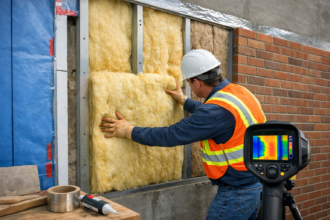
Infrared thermography during heating season reveals secondary damage before visual inspection does. Wet insulation or wet cavity conditions at clip locations show as anomalous cold spots in IECC Climate Zone 5 and 6 buildings, where the temperature differential between interior and exterior is large enough to generate readable contrast.
By the time thermography shows a wet condition, the water control layer has been failing for at least one full seasonal cycle.
Pull-out testing of demountable clips after two or more removal cycles routinely shows capacity reductions of 15 to 30 percent compared to virgin installation values, based on field measurements from failure investigations. That reduction is not accounted for in the original structural calculations, which used manufacturer-stated allowable loads derived from first-installation testing.
The structural engineer of record stamped drawings based on data that no longer represents the field condition. That is a liability exposure that the profession has not yet fully reckoned with.
The investigation pattern also reveals a documentation failure that compounds the physical one. Closeout packages for demountable rainscreen systems rarely include a reinstallation procedure specific to the clip typology installed.
The project manual may reference the manufacturer’s standard installation guide, but that guide addresses first installation, not the second or third. When a tenant changeover requires panel removal eighteen months after occupancy, the contractor performing the work has no project-specific guidance on isolator pad positioning, sealant reapplication sequence or engagement depth verification.
The work gets done by inference and the inference is frequently wrong in ways that do not become visible until the next rain event drives water through the gap that the inference created.
Moisture mapping using pin-type resistance meters on the substrate framing behind failed demountable clip zones consistently shows elevated readings that extend well beyond the visible stain boundary on the interior finish. A 300-millimeter water stain on gypsum board typically corresponds to a wet zone on the sheathing that is two to three times larger in area, because water migrates laterally through the cavity insulation before it reaches the interior surface.
By the time the building owner calls for an investigation, the remediation scope is already larger than the visible damage suggests. Removing panels to access the substrate for drying and repair is straightforward in a demountable system, which is a genuine advantage over fixed cladding in that specific scenario.
The irony is that the demountability feature that makes remediation easier is also the feature that created the failure pathway in the first place.
Specifying Demountable Systems Without Compromising the Envelope
The answer is not to stop specifying demountable systems. The embodied carbon argument is real, the adaptive reuse economics are real and the demand for facade flexibility will not reverse.
The answer is to specify demountable systems with the same rigor applied to any high-risk attachment condition, which means requiring cyclic testing before system acceptance.
A defensible specification for a demountable rainscreen system should require the manufacturer to submit pull-out and shear capacity data for the clip engagement after a minimum of ten removal and reinstallation cycles, tested in accordance with a protocol derived from ICC-ES AC428 structural testing requirements. It should require water penetration testing per ASTM E1105 performed on a mock-up that has been through those same ten cycles, not on a virgin installation.
It should require a written reinstallation procedure that a trade contractor unfamiliar with the original installation can follow without ambiguity and it should require that procedure to be included in the project closeout documents.
The WRB behind the clip zone cannot be segmented or omitted. The water control layer must be continuous through the clip attachment points, with sealant detailing at each clip penetration that survives removal and reinstallation.
If the system geometry makes that continuity impossible to maintain through repeated cycling, the system is not suitable for the application regardless of its sustainability marketing. That is not a harsh judgment.
It is the minimum standard the building deserves.
The ten-cycle threshold for pre-submission testing is a starting point, not a ceiling. For a building with a stated 20-year adaptive reuse horizon and a three-year average tenant occupancy, the facade could realistically see six to seven full removal and reinstallation cycles across its service life.
A specification that requires ten-cycle testing provides a margin above that expected service demand, but the project team should document the assumed cycle count in the basis of design narrative so that future owners understand the tested service envelope. That documentation belongs in the owner’s project requirements, the basis of design and the operations and maintenance manual, not just the project manual that gets filed after construction closes out.
Preconstruction mock-up requirements should be structured to simulate field conditions rather than laboratory conditions. The mock-up should be assembled by the crew that will perform the actual installation, not by the manufacturer’s representative.
It should be cycled through at least three removal and reinstallation sequences before the water penetration test is performed, with each cycle documented by the building envelope commissioning agent. The commissioning agent should verify isolator pad position, sealant bead continuity and clip engagement depth at each cycle, not just at the final installation before testing.
That verification sequence creates a record of how the system behaves under field conditions and identifies training gaps before they become failures on the building skin.
Substitution requests for demountable systems during construction administration require the same level of scrutiny as substitution requests for any other structural attachment. A contractor who proposes substituting a snap-lock demountable system for the specified hook-and-rail system because the snap-lock product has a shorter lead time is proposing a change in attachment typology, load path geometry and post-cycling performance characteristics, not just a change in panel supplier.
The architect and structural engineer of record both need to review that substitution against the post-cycling test data requirements in the specification and the contractor needs to provide that data before the substitution is approved. The construction schedule pressure that drives most substitution requests does not reduce the structural or hygrothermal risk of accepting an untested system.
It only reduces the time available to evaluate it.