
- Millions of square feet of 1980s and 1990s precast spandrel facades are entering their first serious forensic review cycles with bearing pads no one planned to replace.
- Neoprene bearing pads fail through four distinct mechanisms including compression set, ozone degradation, thermal fatigue and chemical attack that each require different field diagnostics.
- Embed plate misalignment stacks construction tolerances from two independent systems and concentrates bearing stress in ways no one verified during original construction.
- Contract document gaps leave bearing pad specification and inspection responsibility unclaimed across structural, precast and envelope scopes of work.
- Communicating pad deterioration as a structural load path failure rather than a maintenance issue is what moves remediation from deferred lists to capital budgets.
Precast Spandrel Bearing Pad Failures: Who Owns This Connection?
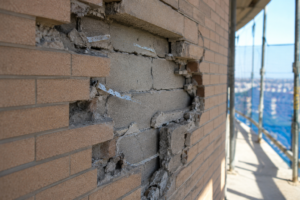
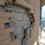
During a routine facade condition assessment on a 1989-vintage office tower, a senior envelope consultant probes a neoprene bearing pad at a spandrel panel seat connection and watches it crumble: not compress: under finger pressure. The pad has lost roughly 60 percent of its original thickness to compression set and ozone degradation and the embed plate above it has rotated measurably out of plane.
No one in the original contract documents owned this connection detail and no one in the current ownership group had budgeted to replace it.
That scenario repeats itself across North American cities right now. The 1980s and 1990s precast boom produced millions of square feet of spandrel panel facades that are entering their first serious forensic review cycles.
Bearing pad replacement is consistently the line item that surprises owners and it surprises them because no one told them these components had a service life.
The Forgotten Interface: What Bearing Pads Actually Do
The neoprene bearing pad at a precast spandrel connection is not a gasket and it is not a shim. It performs three distinct structural functions simultaneously: it distributes concentrated gravity load from the panel edge across the bearing seat, it accommodates dimensional tolerances between the precast panel soffit and the structural ledger and it provides a compliant interface that isolates thermal and seismic movement between the panel and the frame.
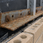
The typical assembly consists of a steel ledger angle or cast-in embed plate welded to the structural frame, a neoprene pad seated on that plate and the precast panel resting on the pad. Separate tieback anchors, typically slotted connections with hairpin reinforcement or welded plate assemblies, resist out-of-plane wind and seismic loads independently.
This matters diagnostically: bearing pad failures manifest as vertical settlement, panel rotation and soffit cracking, while tieback failures produce out-of-plane displacement and cracking at the panel top anchor.
Pad geometry is not arbitrary. A standard pad for a mid-weight spandrel panel, typically in the 12,000 to 18,000-pound range, runs 4 to 6 inches in the bearing direction and 6 to 8 inches along the panel length, with a thickness of 3/8 to 1/2 inch.
That thickness is the compliance budget for the entire connection. Too thin and the pad cannot absorb differential thermal movement without transferring shear force to the embed plate weld.
Too thick and the pad becomes unstable under eccentric load, tending to walk or extrude laterally from beneath the panel edge. The PCI Design Handbook, 8th Edition, Chapter 6 establishes connection design principles and identifies bearing pads as a serviceable component with an assumed finite life.
That language exists in the handbook. It rarely makes it into the project closeout documentation that an owner actually reads.
The gap between what the handbook assumes and what the operations and maintenance manual contains is where deferred failures accumulate.
How Neoprene Degrades: Four Mechanisms Consultants Must Recognize
Neoprene bearing pads fail through four distinct mechanisms and experienced assessors need to recognize each one because the field evidence looks different and the remediation urgency differs.
Compression set is the baseline failure mode. Under sustained gravity load over decades, neoprene loses its elastic recovery capacity.
The pad deforms permanently, reducing effective bearing area and eventually transferring load directly to steel-on-steel contact at the embed plate edge. ASTM D395 defines the laboratory test method for compression set; field confirmation comes from measuring residual pad thickness against the original specification and observing whether the pad rebounds at all when panel load is temporarily relieved during investigation.
A pad at 40 percent of its original thickness with no measurable rebound has failed in compression set regardless of how it looks on the surface. On a project assessed in 2021 involving a 1987 office building in the upper Midwest, extracted pad samples tested at 78 percent compression set against an ASTM D395 Method B limit of 35 percent.
The pads had been in continuous service for 34 years without a single inspection entry in the building maintenance log.
Ozone and UV degradation attack the pad surface and progress inward. Spandrel zones, by definition, sit at the exterior face of the floor plate with high UV exposure.
In urban environments, ambient ozone concentrations accelerate surface crazing and cracking in neoprene at a rate that correlates with building orientation and proximity to traffic corridors. South and west exposures on buildings within two blocks of high-traffic arterials consistently show more advanced surface degradation than north-facing facades on the same structure.
What looks like minor surface checking on a visual survey can mask through-cracking at the pad interior. A probe or pick inserted at the pad edge on a degraded sample will often penetrate 1/4 inch or more into what appears from the face to be intact material.
Thermal cycling fatigue accumulates damage that is not visible until the assembly has already redistributed load. The panel-to-frame interface experiences differential thermal movement every day.
Neoprene accommodates that movement through micro-shear within the pad thickness. After approximately 20 to 25 years of service, cumulative fatigue damage reduces the pad’s shear compliance and it begins transferring thermal forces to the anchor hardware rather than absorbing them.
The field indicator is cracking at the panel soffit near the bearing zone, oriented perpendicular to the panel length, which maps the location where the panel is rocking on a pad that no longer absorbs movement. Consultants who attribute that crack pattern to shrinkage without probing the bearing connection are missing the load path story.
Chemical attack and moisture infiltration complete the failure sequence. Water entry at deteriorated sealant joints introduces chlorides to the connection cavity, accelerating corrosion of the embed plate and ledger angle.
Wet-dry cycling causes the pad to swell and contract dimensionally, which destabilizes its seating position. In coastal environments or in northern climates where deicing salts migrate up the facade through capillary action, chloride-induced corrosion of the embed plate can undercut the pad bearing area from below, leaving the pad effectively bridging a corroded void.
ASTM D2240 durometer hardness testing provides a field-expedient screening tool: neoprene pads specified to 50 to 60 Shore A at installation commonly test above 80 Shore A after 30 years of service. At that hardness, the pad is effectively rigid and provides none of its intended compliance.
A pad reading 85 Shore A is transmitting thermal and seismic movement directly to the structural connection rather than absorbing it, which is a load path change the original structural engineer of record never accounted for.
Misaligned Embed Plates: The Variable That Multiplies Bearing Stress
Embed plate misalignment is not a defect in the traditional sense. It is the predictable result of stacking two independent tolerance systems on top of each other without a verification step in between.
The structural frame carries its own construction tolerances per ACI 117-10, which allows column face variation and floor-to-floor elevation differences that accumulate over the building height. The precast erection then adds its own tolerance stack.
PCI MNL-135, the Tolerance Manual for Precast and Prestressed Concrete, establishes erection tolerance limits for bearing seat elevation at plus or minus three-quarters of an inch. On a 12-story building, that tolerance, applied in the same direction at each floor, produces a cumulative offset that can place a bearing pad at the extreme edge of its intended seat.
The load path consequence is direct. A bearing pad seated on a tilted or laterally offset embed plate concentrates load at one edge of the pad rather than distributing it across the full bearing area.
That edge concentration creates a stress riser that accelerates compression set locally, initiates splitting tension in the panel soffit concrete and, in cases where the panel edge cantilevers past the bearing point, can produce a shear failure plane at the panel end. A 6-inch-wide pad carrying 15,000 pounds of panel weight at full bearing area sees approximately 625 pounds per square inch of average contact stress.
The same load concentrated at a 1-inch edge strip, which is what a severely tilted embed plate produces, generates contact stress that exceeds the bearing capacity of standard 5,000 psi precast concrete at the panel soffit corner.
Visual indicators during assessment include panel edge rotation relative to the structural grid, mortar or grout extrusion at bearing seats (which maps the direction of panel movement), rust staining patterns that reveal embed plate geometry through the panel soffit and measurable panel tilt documented with a digital inclinometer. A tilt reading greater than 1/8 inch per foot at the panel soffit, measured perpendicular to the facade plane, warrants immediate connection investigation regardless of the pad’s surface condition.
The contractual gap here is specific: structural engineers of record specify embed plate location tolerances but do not inspect bearing pad installation. Precast fabricators install pads per shop drawings but do not verify field conditions after erection.
General contractors close out the precast subcontract based on visual acceptance of the panel installation, not on verification of bearing pad seating geometry. No one closes that loop and the building owner inherits a connection assembly that may have been misaligned from day one.
Why the Contract Documents Create an Ownership Gap
The bearing pad sits at the intersection of three separate scopes of work and falls cleanly within none of them. This is not a criticism of any individual practitioner.
It is a structural problem in how precast facade projects are contracted and documented.
The structural engineer of record designs the embed plate and ledger angle, specifies weld sizes and steel grades and establishes the load that the connection must carry. The precast engineer of record (typically the fabricator’s engineer of record) designs the panel geometry, the connection hardware cast into the panel and the tieback anchor assembly.
The envelope consultant, if retained at all during original construction, addresses sealant joint design and weatherproofing. Bearing pad material specification, installation inspection and long-term serviceability fall between all three scopes.
CSI MasterFormat 2020 makes this concrete. Section 03 45 00 covers Precast Architectural Concrete.
Section 05 05 23 covers Metal Fastenings. The bearing pad assembly, which is neither purely precast concrete nor purely metal fastening, lives in the gap between those two division assignments.
In practice, bearing pad specification most often appears as a single line item in the precast subcontractor’s shop drawing submittal, referencing a generic neoprene pad to a Shore A hardness range with no durometer verification requirement, no installation inspection hold point and no reference to ASTM D2000 material classification for long-term weathering performance. On competitively bid projects, that gap means no subcontractor carries explicit responsibility for the complete connection assembly as a system.
The shop drawing review process compounds the problem. The structural engineer of record reviews the embed plate geometry and weld details.
The precast fabricator’s engineer stamps the panel connection hardware. The bearing pad, submitted as a product data sheet rather than a designed element, passes through review without anyone calculating the contact stress under the specified load or verifying that the pad dimensions match the actual bearing seat geometry as built.
On projects where the structural frame was cast with embed plates at the outer tolerance limit and the precast panels were erected at their outer tolerance limit in the same direction, the bearing pad is asked to perform at conditions no one ever checked against the pad specification.
The downstream consequence surfaces during forensic assessment: no as-built documentation of pad thickness, no record of durometer specification, no manufacturer data sheet in the project file and no maintenance provision in the original operations and maintenance manual. Owners have no baseline against which to measure current conditions and consultants have no specification to enforce.
The assessment team is left reconstructing the original design intent from PCI handbook tables and whatever shop drawing fragments survive in the building archive.
What a Competent Assessment Protocol Actually Requires
A facade condition assessment on a precast spandrel system older than 25 years needs to treat bearing pad evaluation as a primary deliverable, not an incidental observation. That means going beyond visual survey.
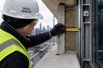
Access matters. Swing stage or suspended scaffold access that allows a consultant to physically probe bearing pads at representative floors, orientations and facade zones is the minimum standard.
Binocular survey from grade or drone photogrammetry will not detect compression set, will not reveal pad crumbling and will not identify the rotational displacement that indicates load redistribution to steel-on-steel contact. If the scope of services does not include physical access to connection zones, the assessment cannot characterize bearing pad condition.
A sampling protocol that covers at minimum 10 percent of connections, stratified by floor level, cardinal orientation and proximity to building corners, provides a statistically defensible basis for extrapolating condition across the full facade. Corner bays warrant higher sampling density because they accumulate biaxial thermal movement and typically show accelerated pad deterioration relative to field bays.
Field testing should include durometer hardness readings per ASTM D2240 at each sampled connection, residual thickness measurement against the original specification (which requires locating that specification, which is its own challenge) and documentation of panel rotation relative to the structural grid using a digital inclinometer. Where access permits, probe the pad edge with a pick or probe to assess surface crazing depth.
A pad that crazes and fragments under probe pressure has lost its functional compliance regardless of its measured thickness. Photograph each connection with a scale reference in frame.
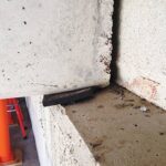
Record the embed plate condition, the presence or absence of corrosion product at the pad perimeter and any evidence of pad migration from its original seated position. Pads that have walked laterally more than 1/4 inch from their original position indicate that the connection has been cycling under thermal load without the pad providing adequate restraint, which means the tieback anchors have been absorbing forces outside their design envelope.
Laboratory confirmation on extracted samples, tested per ASTM D395 for compression set, provides defensible data for remediation recommendations and for communicating urgency to building owners who are accustomed to deferring facade maintenance. When extracted samples also undergo ASTM D412 tensile testing, the results frequently show elongation at break values below 100 percent against a new neoprene baseline of 300 to 400 percent, which quantifies the degree to which the material has embrittled.
That number, presented alongside a photograph of a crumbled pad, is more persuasive in a client meeting than a Shore A hardness reading alone.
Communicating Risk to Owners Who Have Never Heard of a Bearing Pad
The technical findings are the easier half of this work. The harder half is translating bearing pad deterioration into language that produces a budget authorization.
Owners of 1980s-vintage office towers are managing assets that have been refinanced, sold and managed by successive ownership groups with no institutional memory of the original construction. They understand roof replacement cycles.
They do not understand that a half-inch neoprene pad carrying 15,000 pounds of precast panel has a service life that expired a decade ago. The asset manager who receives a facade assessment report referencing ASTM D395 compression set values and Shore A hardness readings will forward it to the property manager, who will forward it to the maintenance supervisor and the finding will stall at every handoff because no one in that chain has a frame of reference for what the numbers mean in terms of building risk.
The communication frame that works in practice is consequence-based rather than material-based. A failed bearing pad that has transferred load to steel-on-steel contact at the embed plate edge is now loading the weld between the embed plate and the structural frame in a way the structural engineer of record never designed for.
That is a statement about structural integrity, not about facade maintenance. It changes the conversation and it changes the budget priority.
Owners who defer sealant replacement for years will authorize emergency shoring within days when the word “weld” appears in the same sentence as “overloaded” and “not designed for this condition.
Photographs of extracted pad samples placed next to a new pad of the same specification communicate condition faster than any test result. A crumbled pad fragment next to an intact pad, labeled with the floor level and facade zone where it was found, answers the question “how bad is it?
” in a format that does not require technical training to interpret. Include a panel weight calculation in the report narrative.
State explicitly that a panel weighing 14,000 pounds is currently bearing on a connection that has lost 60 percent of its designed bearing area. Owners understand weight.
They understand that 14,000 pounds needs to be supported by something that is actually functional.
Document the load path consequence explicitly in the assessment report. Quantify the panel weight.
Reference the design bearing area versus the observed effective bearing area. If the embed plate shows rotation, note that the tieback anchors are now resisting a moment load in addition to their designed lateral load.
Give the structural engineer of record a reason to issue a letter of concern. That letter is what moves bearing pad replacement from the deferred maintenance list to the capital budget.
A structural engineer’s letter of concern, even one that stops short of declaring an unsafe condition, triggers insurance carrier review on most commercial properties. That review, in turn, applies pressure that no assessment report can generate on its own.
The Remediation Budget Gap Nobody Planned For
Bearing pad replacement on an occupied mid-rise building is not a simple maintenance task. It requires temporary shoring of each panel, removal of the deteriorated pad, surface preparation of the embed plate (which is frequently corroded), installation of a new pad to current specification and re-engagement of the panel with all tieback hardware verified and re-torqued.
The shoring requirement is where the budget escalates beyond what owners initially anticipate. Each panel must be temporarily supported while its bearing pad is replaced, which means erecting shoring towers or installing needle beams through the spandrel zone at each connection.
On an occupied building, that work requires coordination with tenants on the affected floors, temporary protection of the occupied space below and, in many jurisdictions, a shoring design stamped by a licensed engineer of record. The shoring design alone can add 15 to 20 percent to the per-connection remediation cost before a single pad is touched.
New pad material must match or exceed the original specification in Shore A hardness and must be sourced from a manufacturer who can provide ASTM D2000 material certification, because the building’s insurer will require documentation that the replacement material meets a defined standard.
On a 15-story building with four bearing connections per spandrel panel and panels at 8-foot centers on a 150-foot-wide facade, the connection count reaches into the hundreds before accounting for return facades and mechanical penthouses. Multiply that by the shoring and access cost for each connection on an occupied building and the remediation budget reaches a scale that surprises every owner who encounters it for the first time.
A project of that scale, executed on a swing stage with a two-person crew replacing four connections per day, runs 60 to 80 working days of access time on the primary facade alone. That timeline has lease implications, insurance implications and lender notification requirements on financed properties that the owner’s facilities team is not equipped to manage without outside coordination.
The practical recommendation from field experience: when a facade condition assessment identifies bearing pad deterioration on more than 20 percent of sampled connections, treat the entire facade as requiring systematic pad replacement rather than spot repair. Spot repair on a 30-year-old precast system produces a patchwork of pad ages and stiffnesses that creates differential movement across the facade.
That differential movement transfers load to the connections that were not replaced, accelerating their failure. A facade with 30 percent of its pads replaced and 70 percent of its original pads still in service is not 70 percent of the way to a solved problem.
The stiffness differential between new 50 Shore A pads and original pads that have hardened to 80 Shore A means the new pads absorb movement that the old pads refuse to accommodate, concentrating fatigue at the new-to-old transition zones.
Budget for the complete system. Assess it as a complete system.
And start that conversation with the owner before the investigation scope is finalized, because the scope that finds the problem has to be large enough to characterize it accurately.