Cementitious Fireproofing at Exposed Steel Facade Frames
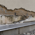
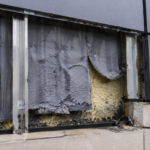
A forensic investigation on a six-year-old mid-rise office building in the Pacific Northwest revealed active corrosion at the base of exposed wide-flange facade columns. The damage wasn’t at the steel itself.
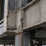
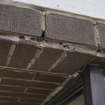
It was precisely at the termination line where cementitious spray-applied fireproofing ended and the cladding attachment bracket began. Moisture had been wicking laterally behind the bracket plate for years, invisible beneath the architectural cladding, while the fireproofing edge had delaminated and lost adhesion across nearly 40% of the sampled connection zones.
The failure was not a product failure. It was a detail coordination failure that no single discipline had owned.
Why Exposed Steel Facades Are Forcing a Fireproofing Coordination Problem
The trend toward architecturally expressed structural steel in commercial mid-rise construction is accelerating. Perimeter moment frames, curtain wall bypass conditions and exposed wide-flange columns are showing up on project after project as architects push for a visible structural expression.
That aesthetic decision creates a fireproofing problem that the industry has not resolved at the specification or detail level.
Fireproofing is typically specified by the structural engineer of record under Division 07. Cladding attachment is detailed by the facade engineer or a delegated design subcontractor under a separate scope. Those two scopes rarely share a coordination meeting and they almost never share a drawing set that shows both systems at the same node.
The result is a gap, not in the building, but in professional responsibility.
Spray-applied fire-resistive material (SFRM) was developed for interior protected steel in conditioned spaces. It performs well in that environment.
Applying it to perimeter columns that terminate near exterior cladding attachment hardware puts it in a condition it was not engineered to handle. IBC 2021 Section 704 governs fire-resistance-rated assemblies at exterior walls and AISC Design Guide 19 addresses fire resistance of structural steel framing, but neither document resolves the coordination gap between the fireproofing applicator’s scope and the facade contractor’s scope.
That gap is systemic and procurement sequences make it worse: fireproofing is applied before cladding attachment details are finalized on most projects.
That sequencing problem has a direct contractual consequence. The fireproofing subcontractor mobilizes early, often immediately after steel erection and decking, because the general contractor needs the floor plates enclosed before interior trades can begin.
Cladding attachment shop drawings, by contrast, are typically not approved until four to six months into the construction schedule on a mid-rise project. The fireproofing applicator has no approved facade attachment drawings to reference when they are standing at the perimeter column with a spray rig.
They terminate the material at whatever hardware is already welded to the steel, which is usually the embed plate or a preliminary bracket location that may not reflect the final approved geometry. When the facade contractor arrives months later with approved shop drawings showing a slightly different bracket position or a larger plate footprint, the SFRM termination condition is already set and largely inaccessible for correction without partial removal.
The general contractor does not typically flag this as a problem because neither subcontract explicitly assigns responsibility for the interface condition. The result is a built termination that no one designed and no one inspected.
How Cementitious SFRM Behaves at Termination Edges
SFRM is a porous, alkaline, vapor-permeable material. In a protected interior environment, that porosity is inconsequential.
At an unprotected termination edge near an exterior cladding attachment, that same porosity becomes the primary failure mechanism.
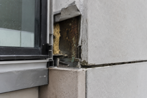
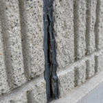
Termination edges at bracket plates, embed plates and cladding anchor zones are typically left raw, uncoated or covered only by a sealant bead applied by whoever noticed the gap last. Sealant at these locations is not specified for compatibility with the SFRM substrate, is not maintained and is not considered a primary water control layer by anyone on the project team.
It is a field improvisation.
Adhesion loss at termination edges accelerates through three mechanisms operating simultaneously. Thermal cycling at the facade moves the bracket plate relative to the SFRM face; the SFRM, being brittle, cannot accommodate that movement without cracking at the bond line.
Vibration from cladding panel wind loads transmits through the bracket into the SFRM termination zone. Freeze-thaw cycling in IECC Climate Zones 5 and above saturates and fractures the SFRM edge over successive winters.
ASTM E605 establishes the procedures for measuring SFRM thickness and density in the field, but those measurements are taken at the field of the section, not at the termination edge. ASTM E736 sets minimum adhesion and cohesion values for SFRM, but no one is pulling samples at bracket plate terminations during construction.
By the time adhesion loss is detectable, capillary action has already been drawing water into the SFRM-to-steel interface from the termination point inward for months or years.
The material properties of gypsum-based and cement-based SFRMs differ in ways that matter at termination edges. Gypsum-based products are more susceptible to moisture degradation at the substrate level; cement-based products are generally more durable in damp conditions but exhibit higher stiffness and are therefore more prone to cracking under differential thermal movement.
Neither product type has a published manufacturer detail for termination at an exterior cladding bracket. Manufacturer technical data sheets for commonly specified products, including those from the major SFRM producers, address minimum thickness, density and application temperature but are silent on termination geometry at connection hardware.
That silence is not an oversight. It reflects the fact that these products were tested and listed for interior column assemblies and the manufacturers have not sought listings for the exterior termination condition because no one has asked them to.
Specifiers who assume that a UL-listed product covers the termination condition at a facade bracket are reading a warranty that does not exist.
The Fire Rating Continuity Problem at Cladding Attachment Zones
IBC 2021 Section 703.2 requires fire-resistance-rated assemblies to be continuous. That requirement is not ambiguous.
What is ambiguous, in practice, is how it applies to the bracket plate, weld plate and through-bolt conditions that interrupt the SFRM envelope at facade attachment points.
SFRM must be applied at the required thickness around all sides of the steel section, including at connection hardware. A bracket plate welded to the flange of a wide-flange column physically interrupts the SFRM envelope.
The fireproofing applicator terminates the material at the plate edge because the plate is already in place and there is no detail telling them to do otherwise. That termination creates an unrated gap at the connection hardware, regardless of what the project specifications say about the field-applied thickness.
UL-listed column assemblies, including those in the UL X701 series, specify minimum SFRM thickness and continuity requirements. Those requirements are routinely violated at facade attachment points, not because applicators are careless, but because the listed assembly was never detailed at the connection condition.
The UL listing assumes a clean column section in a protected environment. It does not contemplate a welded bracket plate with a cladding system installed over it.
AHJ interpretation on this point varies widely. Some plan reviewers treat a cladding bracket as a penetration requiring a rated through-penetration firestop.
Others treat it as an interruption of the rated assembly requiring compensating SFRM thickness. Most do not address it at all.
Specifiers are not resolving this ambiguity in the contract documents and that omission transfers the risk to the field. AISC Code of Standard Practice Section 10 addresses delegated design responsibilities, but it does not resolve who owns the coordination between the fireproofing scope and the facade attachment scope.
The practical consequence of this AHJ variability is that the same detail condition can pass inspection in one jurisdiction and fail in another, with no change to the underlying construction. In jurisdictions where the building official defers to the UL listing without examining the connection condition, the rated assembly is accepted on paper while the actual field condition at the bracket plate remains unrated.
Special inspection programs under IBC Chapter 17 require periodic SFRM thickness verification, but those inspections are scheduled for the field of the column section and are not typically extended to connection hardware. The special inspector’s report documents compliance with the listing at the locations that were measured.
It does not document the termination condition at the bracket plate because that condition is not part of the inspection protocol. The result is a record of compliance that does not reflect the actual fire-resistance condition of the assembly at its most vulnerable point.
Anatomy of the Moisture Trap the Detail Actually Creates
The physical geometry of this condition is straightforward. A bracket plate is welded or bolted to the steel flange.
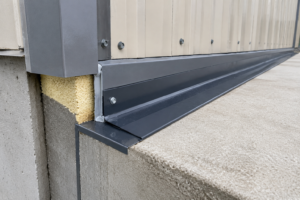
SFRM is terminated at or near the plate edge, either flush with the plate face or slightly short of it. The cladding system is then installed over the bracket, creating a concealed interstitial cavity between the back face of the cladding panel and the face of the SFRM termination.
That cavity is not drained. It is not ventilated.
It is not accessible after cladding installation. It is a classic trapped moisture condition and every source of water in the building envelope feeds it.
Condensation accumulates at the cold steel surface within the cavity during heating season. Wind-driven rain infiltrates through imperfect sealant joints at the cladding perimeter.
Construction moisture trapped during enclosure contributes an initial load. The SFRM, being porous and hygroscopic, absorbs and holds that moisture against the steel substrate rather than allowing it to drain or evaporate.
The bracket plate itself creates a horizontal shelf that prevents any drainage that might otherwise occur.
Corrosion at this zone initiates at the steel surface beneath the SFRM termination edge, where moisture concentration is highest and oxygen availability is sufficient. NACE SP0169 establishes thresholds for corrosion initiation at steel surfaces in contact with moisture; the conditions at this node routinely exceed those thresholds within the first two to three years of service.
By the time the corrosion is detectable, section loss may be structurally significant. ASTM C1583 pull-off testing, used in forensic assessment of SFRM adhesion, consistently shows near-zero bond values at these termination zones in buildings five years and older.
Published proceedings from IIBEC field investigations confirm this pattern across multiple building types and climate zones.
The thermal bridging behavior of the bracket plate compounds the moisture problem in ways that are rarely modeled during design. A steel bracket plate welded to a wide-flange column flange conducts heat out of the building at a rate that depresses the surface temperature of the steel in the concealed cavity well below the dew point of interior air during heating season.
THERM modeling of typical bracket plate geometries in Climate Zone 5 conditions shows surface temperatures at the back face of the bracket plate dropping to 38 to 42 degrees Fahrenheit during design winter conditions, while interior relative humidity at 35% produces a dew point of approximately 37 degrees Fahrenheit. The margin between surface temperature and dew point at this location is effectively zero, meaning condensation is a near-certain outcome during any sustained cold weather period.
Primer and shop-applied paint systems on the steel provide some initial corrosion resistance, but those coatings are compromised at weld zones and at the SFRM-to-steel interface where adhesion loss has already occurred. Once the coating is breached, bare steel in a persistently wet, oxygen-available environment corrodes at rates that can produce measurable section loss within three to five years of initial exposure.
What the Specifications and Shop Drawings Are Missing
Standard SFRM specifications, typically based on MasterSpec Section 07 81 00, describe field application procedures, minimum thickness requirements and density testing. They do not address termination conditions at exterior cladding attachments.
The specification tells the applicator how thick to spray the material and how to test it. It says nothing about what to do when the spray path ends at a bracket plate face.
Shop drawings for cladding attachment systems show the bracket geometry, the fastener pattern and the connection to the primary structure. They rarely show the SFRM termination condition.
The fireproofing applicator is not in the room when the cladding attachment shop drawings are reviewed and the facade contractor is not present when the fireproofing submittals are approved.
The fireproofing applicator terminates SFRM at the face of the bracket plate as a practical field decision. That is not a designed termination.
It is a default one, made by a tradesperson trying to complete their scope cleanly. No one has told them otherwise because the specification does not address it and the detail drawings do not show it.
The missing specification language is specific. It includes: the termination sealant type and its tested compatibility with the SFRM substrate; the minimum return dimension of SFRM onto the bracket plate face; the required overlap or transition treatment at embed plates and weld plates; and explicit assignment of inspection responsibility at concealed termination zones before cladding installation begins.
That inspection requirement is the most important omission. Once the cladding goes on, the termination condition is inaccessible and unverifiable for the life of the building.
The submittal process makes this worse in a specific and predictable way. Section 07 81 00 submittals typically include the manufacturer’s product data sheet, the UL listing number and a sample application procedure.
The structural engineer of record reviews those submittals for conformance with the specified product and thickness. The submittal review does not include a drawing showing how the SFRM terminates at each bracket plate type on the project, because no such drawing exists in the submittal package and none is required by the specification.
The architect’s submittal log shows the fireproofing submittal as approved. The facade contractor’s submittal log shows the cladding attachment shop drawings as approved.
Neither approval record references the other and no combined review of the interface condition ever occurs. The project record documents two approvals that together leave the most critical detail on the project unresolved.
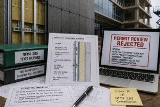
Closing that gap requires a specific submittal requirement: the fireproofing applicator’s shop drawings must include a detail for each unique bracket plate condition on the project, reviewed and approved by both the structural engineer of record and the facade engineer before application begins at any perimeter column location.
Closing: The Detail You Need to Write Before the Next Project Goes to Bid
The coordination failure described in this article is not rare. It is the default outcome when fireproofing and facade attachment are treated as separate scopes with no shared detail obligation.
Every exposed steel facade project with cementitious fireproofing has this condition somewhere. Most of them have never been looked at.
The fix is not a new product. It is a detail and a specification clause written before the project goes to bid.
The detail needs to show the SFRM termination condition at each bracket plate type, with a minimum return dimension onto the plate face, a compatible termination sealant and a note assigning inspection responsibility to a named party before cladding installation. The specification needs to reference that detail explicitly in Section 07 81 00 and require the fireproofing applicator to coordinate with the facade contractor’s approved shop drawings before application begins at any perimeter column location.
The named inspection party matters. Assigning that responsibility to the special inspector of record, with a specific hold point in the inspection program that prevents cladding installation from proceeding until the SFRM termination condition at all perimeter bracket locations has been documented and photographed, creates a contractual mechanism that does not currently exist on most projects.
That hold point should appear in the project’s Statement of Special Inspections under IBC Section 1705.14, which governs special inspection of fire-resistant penetrations and assemblies. Most Statements of Special Inspections on exposed steel facade projects do not include a line item for SFRM termination at cladding attachment hardware.
Adding that line item costs nothing at the document preparation stage and eliminates the primary mechanism by which this condition goes undetected for the life of the building.
If you are detailing an exposed steel facade frame right now and your drawing set does not show the SFRM termination at the cladding bracket, you have an open liability. Close it before the steel goes up, not after the cladding comes down.