
Expansion Joint Cover Assemblies at Exterior Wall Planes: Where the Movement Capacity Assumption Fails and Why the Substrate Transition Detail Is the Primary Source of Water Intrusion
A forensic investigation on a nine-year-old mixed-use tower in the mid-Atlantic region revealed chronic water intrusion at the 4th and 8th floor spandrel zones. Not from the curtainwall system that received three rounds of remediation.
From undersized expansion joint covers that had exhausted their rated movement capacity within the first two heating-cooling cycles. The substrate transition from precast spandrel panel to metal stud backup wall had never been continuously backed, leaving the joint cover anchor leg cantilevering over a void.
The cladding contractor absorbed four years of blame before anyone pulled the cover off the wall and looked at what was behind it.
That sequence is not unusual. It is the standard failure pattern.
The Movement Capacity Assumption That Gets Built Into Every Project
Most expansion joint covers on commercial projects get specified using rule-of-thumb joint widths: 1 inch or 2 inches, selected by the project architect based on what appeared in the last project’s specification section rather than calculated movement demand. MasterSpec Section 07 95 13 provides a framework, but it does not mandate movement calculations as a submittal requirement.
The result is that joint width and cover selection proceed on assumption rather than analysis.
The confusion between design movement capacity and total rated travel makes this worse. Manufacturers publish total travel figures in their technical data.
What they do not always state prominently is that usable design capacity is typically 50 percent of that figure. The remaining 50 percent exists as a buffer against contact stress at the extremes of travel.
Specify a cover rated for 1 inch of total travel on a joint that demands 3/4 inch of actual movement and you have consumed most of your usable capacity before the building finishes its first year of thermal cycling.
Tall buildings and geometrically complex structures generate differential movement between dissimilar structural bays that exceeds what standard specification sections anticipate. AISC Design Guide 3 provides inter-story drift context that, when applied to actual building geometry and height, produces movement demand numbers that frequently exceed the embedded assumptions in a 1-inch nominal joint.
The gap between assumed and actual movement is rarely caught at submittal review because the calculation was never required in the first place.
That gap compounds across building height. A 15-story concrete frame building in Climate Zone 5 with a 100-degree Fahrenheit annual temperature differential across an exposed concrete spandrel will generate thermal movement in the range of 3/8 inch to 1/2 inch per 20-foot bay, depending on material coefficient and restraint conditions.
Add inter-story drift from wind loading at upper floors and the cumulative demand at a horizontal joint between the 12th and 13th floors can exceed 3/4 inch of total movement. A 1-inch nominal joint cover with 50 percent usable capacity is already at its design limit before wind and seismic contributions are added.
The calculation takes less than an hour. It is almost never done.
The submittal review process does not catch this because reviewers are checking dimensions against the contract document joint width, not checking the joint width against a movement demand calculation. If the drawings show a 1-inch joint and the submittal shows a cover rated for a 1-inch joint, the submittal gets approved.
The underlying question of whether 1 inch was the right number never gets asked. Requiring a movement demand calculation as a condition of submittal approval, formatted to show thermal, wind and seismic contributions separately, would surface this gap on every project where it exists.
How Expansion Joint Cover Systems Are Actually Rated and What the Numbers Don’t Tell You
Manufacturer movement ratings come from controlled laboratory conditions. Anchor spacing, substrate flatness and thermal gradient at time of installation all affect field performance.
None of those variables appear in the published rating. That is a significant limitation that practitioners need to carry into every submittal review.
ASTM E1399 governs cyclic movement testing for expansion joint covers, but it tests the seal element in isolation. The full assembly, including anchor legs, backing substrate and transition conditions, is not part of the test protocol.
A cover can pass E1399 and still fail in the field within two years if the backing condition is wrong.
The compression-only versus compression-extension distinction is where submittals most frequently go unreviewed at the level of detail that matters. A joint that opens in winter and closes in summer requires a cover rated for extension.
Specifying a compression-only cover on that condition is a guaranteed failure mode. It happens on projects regularly because the reviewer is checking dimensions, not movement directionality.
Published cycle life data, often cited at 10,000 cycles, does not account for combined loading. Simultaneous thermal movement, wind-induced racking and seismic drift create a loading condition that degrades seal elements and anchor connections faster than any single-axis laboratory cycle test will predict.
The number on the data sheet is a controlled-condition figure. Field life under combined loading is shorter.
What the data sheet also does not capture is the effect of installation temperature on initial compression set. A neoprene or EPDM seal element installed at 95 degrees Fahrenheit in August carries a different initial compression state than the same element installed at 35 degrees Fahrenheit in January.
The manufacturer’s rated movement capacity assumes installation at a mid-range temperature, typically around 70 degrees Fahrenheit. An element installed at temperature extremes starts its service life already displaced from the neutral position, which reduces effective travel in one direction before the building has experienced a single seasonal cycle.
Field installation records almost never document ambient temperature at time of cover installation, which means this variable is invisible during forensic investigation unless the investigator specifically asks for it and the contractor’s daily logs are detailed enough to contain it.
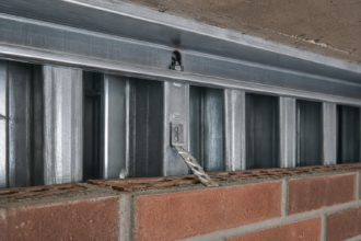
Anchor spacing is a second field variable that the published rating does not address directly. Most manufacturer installation instructions specify maximum anchor spacing in the range of 12 to 18 inches for standard covers, with reduced spacing at corners and transitions.
In practice, anchors get installed at whatever spacing the installer finds convenient, which on metal stud substrates often means spacing driven by stud location rather than cover performance requirements. An anchor leg that spans 24 inches between fasteners on a 20-gauge metal stud substrate will deflect under wind load in a way that the laboratory test specimen, anchored to a rigid steel fixture, never experienced.
That deflection translates directly into cover rotation and nose separation at the joint face.
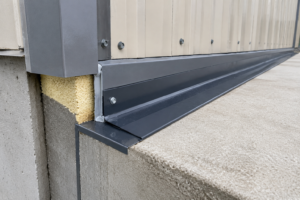
The Substrate Transition Problem: Why the Backing Condition Is the Primary Failure Point
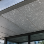
The most common failure condition in exterior expansion joint cover assemblies is not seal material degradation. It is the transition from one substrate type to another across the joint.
Precast to metal stud, concrete frame to CMU, concrete to light-gauge backup: each substrate carries different stiffness, different thermal mass and different surface plane tolerance. Where those substrates meet at a joint, the backing condition for the anchor leg on one or both sides is almost always discontinuous.
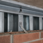
When an anchor leg lands on a substrate transition where blocking, framing or embedment is missing or interrupted, the leg cantilevers over a void. Under thermal cycling and wind load, the cover rotates.
That rotation breaks the compression fit between the cover nose and the joint face. Water enters through the gap between the nose and the face, not through seal material failure.
The water control layer is defeated at the joint face, not at the seal element.
This is the primary water intrusion pathway in joint cover failures. Practitioners who focus remediation on the seal element without addressing the backing condition will see the failure return within one to two heating-cooling cycles.
The contract documents almost never show this condition correctly. Transition details at substrate changes are routinely left to “field verify and coordinate” language in the specifications, which means no trade owns the condition and no one resolves it before the cover goes on.
The structural drawings show the precast embed. The framing drawings show the metal stud layout.
Neither drawing shows the continuous blocking required to give the joint cover anchor leg a substrate to bear against across the transition zone. ASTM E331 water penetration testing under static pressure will confirm that the assembly fails at this condition and NIBS Guideline 3 on enclosure commissioning identifies substrate transition verification as a specific pre-installation checkpoint.
Neither reference prevents the failure if the detail was never drawn.
The division of responsibility between trades makes this worse in a predictable way. The joint cover is typically furnished and installed by the caulking and sealant subcontractor or the specialty metals subcontractor, depending on how the work is divided in the project manual.
The blocking and framing behind the joint is the responsibility of the framing subcontractor. The precast embed is the responsibility of the precast erector.
No single trade has line-of-sight responsibility for the complete backing condition across the transition and the general contractor’s superintendent is rarely looking at joint cover anchor conditions during framing inspections. The enclosure commissioning process described in NIBS Guideline 3 assigns a specific verification step to this condition, but enclosure commissioning is still not standard practice on the majority of commercial projects.
The result is that the backing discontinuity gets covered up by the joint cover, concealed by the cladding system and not discovered until water intrusion forces an investigation years later.
Reading the Forensic Evidence: How to Distinguish Joint Cover Failure from Cladding Failure
Water intrusion from joint cover failure presents as a linear, elevation-consistent pattern that tracks the joint line. It does not present as discrete staining at cladding penetrations or sealant interfaces.
When the water map shows a continuous wet trace along a horizontal or vertical joint line that crosses multiple cladding units, the joint cover is the primary suspect. That pattern is diagnostically distinct from cladding failure, which produces point-source or interface-specific staining.
Infrared thermography and spray rack testing adapted from ASTM E1105 can isolate the joint cover as the source, but the test protocol must pressurize the joint cavity independently from the cladding cavity. Testing the cladding assembly without isolating the joint cavity will produce ambiguous results and will support the misdiagnosis.
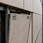
Physical investigation findings that confirm joint cover failure are specific: the cover nose lifted or rotated away from the joint face, anchor fasteners backed out or stripped in the substrate and the seal element compressed asymmetrically or extruded laterally rather than uniformly. These are not subtle findings.
They are visible the moment the cover is removed. The problem is that the cover is rarely removed in preliminary investigations.
Misdiagnosis as cladding failure persists because of proximity bias. The cladding is visible and accessible.
Pulling a joint cover requires a decision to look there specifically and that decision usually requires someone to have already ruled out the more accessible systems. ASTM E2128 provides a systematic wall leakage investigation protocol that, when followed, leads the investigator to the joint cover backing condition before the third round of cladding remediation.
The cost consequence of misdiagnosis is significant and consistently underestimated at the start of investigations. A single round of curtainwall sealant remediation on a mid-rise tower typically runs between $150,000 and $400,000 depending on access method and scope.
Three rounds of that remediation, applied to a problem that originated behind the joint cover, represents a remediation expenditure that could have been avoided entirely if the investigation protocol had required joint cover removal as a first-phase step. ASTM E2128 Section 7 specifically identifies expansion joint covers as a discrete system requiring independent investigation, separate from the cladding system evaluation.
Investigators who compress the protocol by evaluating the cladding and the joint cover as a single assembly will miss the source condition in the same way the preliminary investigations on the mid-Atlantic tower missed it for four years. The linear stain pattern is the diagnostic signal.
When that pattern appears, the joint cover comes off before any cladding remediation is authorized.
Detailing the Substrate Transition Correctly: The Specific Conditions That Must Be Shown
The detail must show continuous blocking or embedment at the full anchor leg length on both sides of the joint. This is not a condition that can be inferred from general notes or left to field coordination.
It requires explicit coordination between the structural, framing and envelope drawings before permit issue.
At precast-to-metal-stud transitions, the standard corrective condition is a steel angle or tube section welded or bolted to the precast embed and extending inboard far enough to provide a continuous bearing surface for the joint cover anchor leg. This element must appear on the drawings with dimensions and connection details.
It cannot be implied. The SMACNA Architectural Sheet Metal Manual addresses blocking and substrate requirements for sheet metal assemblies in terms that apply directly to joint cover anchor conditions; the same principles govern here.
Sealant backing at the joint face, specifically backer rod and sealant at the cover nose contact zone, must be shown as a secondary water barrier. The cover compression fit is the primary water control element.
The sealant is the redundant line of defense. Details that show only the sealant, without showing the cover compression fit as a separate and primary condition, have inverted the performance hierarchy and will produce assemblies that depend on the secondary element to carry primary load.
Transition details at floor-to-wall and wall-to-roof intersections require three-dimensional coordination drawings. A single section cut does not capture the corner condition, which is where backing discontinuity is most severe and most consistently omitted.
The corner is where the anchor leg on the wall plane meets the anchor leg on the floor plane and neither has continuous backing through the turn. IBC Section 1403.2 establishes the weather protection performance obligation that the detail must satisfy.
The detail as drawn must demonstrate how that obligation is met at the corner, not just in the field of the wall.
Specify the blocking material, the connection method and the minimum bearing length for the anchor leg explicitly. Do not use the phrase “provide continuous backing as required.
” That language has produced more failed joint cover installations than any other single specification error.
The minimum bearing length for the anchor leg is a number that should appear on the drawing, not in a general note. For standard extruded aluminum covers with anchor legs in the range of 2 to 3 inches, the bearing surface behind the anchor leg should extend a minimum of 1-1/2 inches beyond the anchor fastener centerline in each direction along the joint.
At substrate transitions, that bearing requirement means the blocking element must bridge the transition by at least that dimension on each side. A steel angle sized at 3 inches by 3 inches by 1/4 inch, welded to the precast embed plate and extending 2 inches past the framing face, satisfies that condition at a precast-to-metal-stud transition and gives the installer a defined surface to fasten into.
That level of specificity is what the detail needs to show. General notes directing the contractor to “provide solid backing” have never produced a correctly executed substrate transition in the absence of a dimensioned detail showing exactly what solid backing means at that specific condition.
The Forward-Looking Condition That Will Accelerate These Failures
Building height and geometric complexity are increasing on commercial projects across IECC Climate Zones 4 through 7, where the thermal delta between summer and winter creates the largest annual movement demand. As projects push past 20 stories with mixed structural systems, the differential movement between adjacent bays will continue to exceed the assumptions embedded in standard specification sections.
The expansion joint cover industry has not significantly changed its product rating methodology in response to this trend. ASTM E1399 still tests the seal element in isolation.
Movement calculations are still not required submittal documentation on most projects. The backing condition at substrate transitions is still left to field coordination on the majority of contract document sets.
The forensic caseload on buildings constructed between 2010 and 2020 is beginning to reflect this gap. Investigations that open with a cladding hypothesis are closing with a joint cover finding.
The building owners who funded three rounds of curtainwall remediation before anyone pulled the cover off the wall are not outliers. They are the leading edge of a pattern that will become more visible as these buildings age into their second decade.
Mixed structural systems are a specific accelerant for this problem. A building that combines a concrete podium with a steel-framed tower above grade 3 generates differential thermal and structural movement at the transition level that exceeds what either system would produce independently.
The concrete podium moves slowly and carries high thermal mass. The steel frame above moves faster and responds more directly to ambient temperature swings.
The joint at that transition level is doing more work than any other joint in the building and it is almost always detailed using the same standard section that applies to joints in the field of the wall. Projects in Climate Zone 6 with this structural configuration, including a significant number of mixed-use residential towers constructed in upper Midwest markets between 2012 and 2019, are now entering the age range where the cumulative effect of under-capacity joint covers and discontinuous backing conditions is producing water intrusion at rates that owners and property managers are attributing to general building aging rather than a specific, correctable design and installation deficiency.
The correction path is not technically complex. It requires three specific changes to standard practice: movement calculations at schematic design, explicit substrate transition details on construction documents and pre-installation inspection of backing conditions before joint covers are installed.
None of those steps requires new technology or new products. They require a decision to treat the expansion joint cover as an engineered assembly rather than a commodity specification item.
Require movement calculations at schematic design. Show the substrate transition detail explicitly.
Pull the cover during pre-installation inspection and verify the backing condition before the anchor screws go in. Those three steps would have prevented every failure described in this article.