

The Deflection Track Detail Is Breaking Your Air Barrier: and Your Energy Model’t Know It
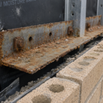
During a forensic investigation of a 6-year-old mid-rise office building in the upper Midwest, an envelope consultant discovered that every floor line along the CFS backup wall showed the same pattern: the air barrier membrane had been cleanly terminated at the deflection track leg, left unconnected to the structure above and the continuous insulation boards had been cut short to accommodate the track’s slip clearance. The condition repeated across 14 floors and four elevations.
It was never flagged during construction observation, never modeled in the thermal analysis and never tested during the air barrier commissioning protocol. The resulting infiltration and thermal bridging losses were estimated to account for more than 40% of the building’s envelope-related energy penalty.
That building is not an outlier. It is a representative sample.
What the Deflection Track Is Actually Doing: and Why It Creates a Problem by Design
The deflection track, also called a slip-track or slotted head track, serves a specific structural function: it allows the top of a non-load-bearing CFS stud wall to move vertically relative to the overhead structure without transferring axial load down through the studs. The studs float inside the track.
The track slots allow that vertical slip. This is intentional, code-compliant framing practice governed by AISI S220 (current edition), which sets deflection limits and head-of-wall clearance requirements for nonstructural CFS members.
The intentional clearance gap between the top of the stud and the overhead structure typically runs from three-quarters of an inch to one and a half inches depending on the calculated live load deflection and seismic drift demand. That gap is not a construction defect.
It is a designed condition.
Here is the problem. The track is designed to move.
Any rigid connection across that joint will experience cyclic stress and eventually fail. Any air barrier membrane bridging the joint must accommodate movement or it will debond, crack or tear.
Any insulation board bearing against the track flange will be subject to the same cyclic loading. Most details drawn at this condition ignore the movement requirement entirely.
The joint gets detailed as if it were static and the assembly pays for that assumption over time.
In high-rise construction, the cumulative vertical deflection under full live load can push the upper end of that clearance range consistently. A 40-story building with concrete flat-plate floors designed for L/360 live load deflection can see measurable seasonal movement at every floor line, not just at the top of the wall.
The deflection track is doing exactly what it was designed to do at every one of those locations. The envelope assembly has to respond to that reality and the detail that ignores movement at the joint is not conservative.
It is wrong from the first day of occupancy.
How the Air Barrier Is Supposed to Cross This Joint: and How It Usually Doesn’t
IECC 2021 Section C402.5 requires a continuous air barrier assembly across all transitions, including structural interfaces. Section C402.5.1 and Table C402.
5. 1.
1 define approved materials and assembly configurations. The language is unambiguous: the air barrier must be continuous at all joints, penetrations and transitions.
The deflection track condition is a transition. Code requires it to be resolved.
In practice, three field conditions break that continuity with near-universal consistency. First, the membrane is terminated at the deflection track leg with no transition detail connecting it to the deck or spandrel above.
The installer runs the membrane to the track, stops and moves on. Second, a fluid-applied membrane is applied over the track without any accommodation for movement.
The membrane cures rigid, the track moves and the bond line fails within the first heating and cooling cycle. Third, backer rod and sealant are used as the sole air seal across the joint, without a flexible transition membrane or proper bond-breaker geometry.
Sealant across a dynamic joint without a two-sided bond-breaker is not an air barrier detail. It is a temporary condition that will fail.
The slotted track geometry compounds every one of these problems. The track flange is narrow.
It is typically galvanized steel with mill oil residue that requires aggressive surface prep before any membrane will bond reliably. The slot pattern physically interrupts substrate continuity, which means membrane adhesion is inconsistent across the flange width even when prep is done correctly.
Installers working at pace on a multi-story project are not stopping to wipe down each track flange with solvent before applying membrane. The prep step gets skipped, the bond is marginal from day one and the first thermal cycle finishes the job.
There is a fourth field condition worth adding to that list: the air barrier membrane is installed correctly on the wall below the track and correctly on the wall above the track, with a gap at the track itself that nobody addresses because each crew assumes the other crew owns the transition. The below-track crew terminates at the track.
The above-track crew starts at the track. The track itself is unaddressed.
This is not a workmanship failure in the conventional sense. It is a coordination failure that the drawing set created by not assigning ownership of the transition explicitly.
One more problem worth naming: ASTM E2357 whole-wall air leakage testing protocols do not isolate the head-of-wall condition as a discrete failure point. A building can pass aggregate air leakage testing while every deflection track line leaks, because the leakage is distributed and diffuse rather than concentrated at a single testable location.
The test is not designed to catch this condition. Relying on it to confirm air barrier continuity at the deflection track is a fundamental misapplication of the standard.
The Continuous Insulation Problem: A Gap That Thermal Models Don’t See
The geometry here is straightforward and the consequence is significant. Continuous insulation boards on the exterior face of a CFS backup wall must terminate or be interrupted at each floor line where the deflection track and the slab edge or spandrel beam occupy the same plane.
The ci layer cannot run continuously through a structural connection point without deliberate detailing to accommodate both the structural geometry and the track’s slip movement. In most field assemblies, it does not.
The typical outcome: insulation boards are cut to fit around the track, leaving an uninsulated band three to six inches wide at every floor line. On a 10-story building with 12-foot floor-to-floor heights, that band repeats nine times per elevation.
The thermal control layer is interrupted at every one of those locations.
Thermal models miss this because they use idealized assemblies. The ASHRAE 90.1-2022 zone-method calculations for CFS-framed walls, documented in Appendix A Table A2.
3, account for stud bridging through the correction factors built into the calculation methodology. They do not include repeating geometric gaps at floor lines.
The model assumes the ci layer is continuous because the specification says it is continuous. The field condition says otherwise.
The scale of the problem is worth calculating explicitly. On a building with 200 linear feet of perimeter per floor and nine floor lines, a four-inch uninsulated band at each floor line represents 600 square feet of wall area with no continuous insulation.
On a building with R-20 ci specified, that 600 square feet is contributing zero insulation value toward the assembly’s thermal performance. If the total opaque wall area is 20,000 square feet, the uninsulated floor-line band represents 3% of the total area by count, but its contribution to heat loss is disproportionate because the uninsulated zone is also typically the location of the highest thermal mass concentration, where the concrete slab edge or spandrel beam is already conducting heat through the assembly.
The ci gap and the structural thermal bridge stack at the same location.
Research from the Building Science Corporation and Oak Ridge National Laboratory on thermal bridging in CFS assemblies documents effective R-value reductions of 15 to 25% from nominal in poorly detailed conditions. The deflection track gap compounds that reduction further.
A wall specified to meet IECC 2021 Table C402.1.3 requirements for Climate Zone 5 with R-20 continuous insulation may be performing at effective R-14 or lower once the floor-line interruptions are accounted for. The energy model shows compliance.
The building does not perform to it.
Why Field Inspections and Commissioning Protocols Routinely Miss It
The inspection sequencing problem is simple: by the time exterior cladding and interior finishes are installed, the deflection track condition is fully concealed. Special inspection for air barriers occurs during installation, but the head-of-wall transition is often completed before the inspector arrives or is immediately obscured by subsequent trades working in sequence.
The window for observation is narrow and frequently missed.
On a typical mid-rise project running multiple floors simultaneously, the framing crew, sheathing crew and membrane crew may be separated by only one or two floors of vertical distance. The membrane installer reaches a floor line, terminates at the track and moves upward.
The exterior wall framing for the next floor is already being set above. By the time a special inspector makes a scheduled site visit, the transition condition at any given floor line may already be covered by sheathing on the upper wall, exterior cladding support angles or both.
The inspector documents what is visible. What is visible is not the problem location.
Commissioning creates a false sense of confidence. Whole-building blower door testing per ASTM E779 or ASTM E1827 measures aggregate leakage but cannot localize the deflection track as a source.
The condition is diffuse, repeating and distributed across the entire building perimeter. It registers as background leakage rather than a discrete failure and a building with significant floor-line air leakage can still return a passing result if the rest of the assembly is tight.
The drawing set problem is equally serious. Air barrier continuity at the deflection track is rarely shown explicitly in construction documents.
The architectural drawings show the track in section. The air barrier specification requires continuity.
The connection between those two facts, the actual transition detail, is left to the contractor to resolve in the field. It usually gets resolved by terminating the membrane at the track and assuming someone else will address the gap.
Nobody does.
The submittal review process does not catch it either. The air barrier manufacturer submits product data and an installation guide.
The installation guide shows the membrane applied to a flat wall with generic transition language at joints. It does not show a slotted deflection track with designed slip clearance.
The design team reviews the submittal, confirms the product meets the specification and approves it. The approved submittal does not resolve the detail.
It confirms the material. Those are not the same thing and treating them as equivalent is how the condition gets built into every floor of a 14-story building without anyone flagging it.
What a Defensible Detail Actually Requires
Resolving the deflection track condition requires treating it as what it is: a dynamic structural joint that must be crossed by both the air control layer and the thermal control layer without compromising either layer’s function or the joint’s structural intent.
For the air barrier, the minimum defensible approach is a flexible transition membrane, typically a self-adhered flashing tape or sheet-applied flexible membrane with documented elongation capacity, that bridges from the backup wall air barrier to the underside of the slab or spandrel above. The transition membrane must be bonded on two sides only, with a free loop at the joint to accommodate slip movement.
A bond-breaker at the midpoint of the joint prevents three-sided adhesion and allows the membrane to deform without tearing. This is not a novel detail.
It is standard practice for expansion joints in fluid-applied systems and should be applied here by the same logic.
The elongation specification matters. A self-adhered flashing tape with 50% elongation at break is not the same product as a sheet membrane rated for 300% elongation.
The deflection track joint will cycle through its full clearance range repeatedly over the building’s service life. A product selected for elongation capacity adequate to a static flashing condition will fail at a dynamic joint.
The specification should call out minimum elongation at break explicitly, with a value calibrated to the designed slip clearance and an appropriate safety factor. A joint with three-quarters of an inch of designed slip in a membrane bonded over a two-inch span is asking for 37% elongation at the bond line under full deflection.
Specifying a product with 50% elongation capacity at break leaves almost no margin. Specifying 200% or greater leaves enough margin that the product survives the joint’s service life without replacement.
For the thermal layer, the solution requires a compressible or segmented insulation strategy at the floor line. Mineral wool batt or semi-rigid board cut to fill the track cavity, combined with ci board returned tightly to the track flange on both the upper and lower wall sections, can close the geometric gap without interfering with slip movement.
The key is that the insulation at the joint must not be rigid-bonded to both the wall and the structure. It needs to accommodate the same movement the track is designed to allow.
Neither of these details is complicated. Both require explicit drawing coordination between the structural engineer’s head-of-wall detail and the envelope consultant’s air barrier and ci continuity details.
That coordination is where most projects fail before the first stud is set.
The Specification Gap That Makes This Worse
Specifications routinely require air barrier continuity and continuous insulation without providing the details that make continuity achievable at the deflection track. Section 07 27 00 in a typical project manual will cite IECC 2021 C402.5 compliance, require the membrane to be continuous at all transitions and reference ASTM E2357 as the performance benchmark.
It will not describe how the membrane crosses a slotted track with three-quarters of an inch of designed slip clearance.
That gap between specification requirement and constructable detail is where the failure lives.
The contractor reads the spec, prices a continuous membrane and installs it to the track. The inspector sees membrane at the track and checks the box.
The commissioning agent runs the blower door and gets a number. The energy model shows compliance.
The building underperforms for its entire service life and the first forensic investigation six years later finds the same condition on every floor.
The specification language that would close this gap is not lengthy. A single paragraph in Section 07 27 00 requiring the contractor to submit a shop drawing showing the proposed transition detail at all deflection track locations, with the detail reviewed and accepted by the envelope consultant before installation begins, would force the resolution of this condition into the pre-construction phase where it belongs.
That paragraph is absent from most project manuals. Adding it costs nothing.
The absence of it costs the building owner 40% of their envelope energy performance for the life of the building.
Section 07 21 13 for board insulation has the same gap. The specification requires ci to be continuous and requires minimum R-values to be maintained at all locations.
It does not address the deflection track as a condition requiring special treatment. A performance note requiring the contractor to submit a floor-line insulation continuity detail for each deflection track configuration on the project, with the submitted detail demonstrating how the specified R-value is maintained across the floor line without interfering with the track’s designed slip clearance, would force that resolution into the submittal process.
It would also give the design team a documented basis for rejecting field conditions that do not match the accepted submittal. Neither the specification nor the submittal process currently provides that basis, which is why the condition gets built in and stays built in.
What Changes When You Treat This Detail as a Primary Coordination Point
The deflection track condition should appear on the air barrier continuity plan as an explicit detail reference, not as a transition covered by a general note requiring continuity. It should be coordinated between the structural drawings and the envelope drawings before the project goes to bid, not resolved by RFI during framing.
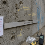
Envelope commissioning protocols on projects where CFS backup walls are present should include visual inspection of the head-of-wall transition before cladding conceals it, with photographic documentation at minimum one location per floor per elevation. Infrared thermography during the first heating season can locate floor-line thermal gaps in the ci layer even after cladding is installed and that data should be a standard deliverable on any project claiming compliance with ASHRAE 90.1-2022 Appendix A thermal performance requirements.
The pre-bid coordination meeting is the right place to establish that the deflection track transition is a primary envelope detail requiring a specific resolution, not a field condition left to the installing contractor’s judgment. When the structural engineer, envelope consultant and specifications writer are in the same room before the project goes to bid, the question of who owns the transition detail and what that detail looks like can be answered once.
When that conversation does not happen, it gets answered differently by every crew on every floor of every project and the answer is almost always the same wrong answer: terminate the membrane at the track and move on.
The deflection track is not going away. It is the right structural solution for non-load-bearing CFS walls in multi-story construction and the movement it accommodates is real.
The envelope assembly has to resolve it. Start drawing that detail before the project leaves the design phase, because the field will not invent it on its own.