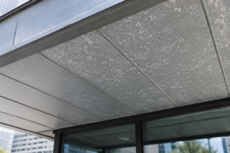
FRP Cladding in Commercial Facade Applications: Thermal Expansion Tolerances, Attachment Limits and the Risks Hidden Behind the Lightweight Assumption
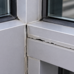
A facade retrofit on a 1980s-era office building in Phoenix specified FRP panels as a direct substitution for aluminum composite material, citing equivalent weight and lower cost. Within 18 months, panel edges had begun delaminating at fastener zones and visible waviness had developed across multiple bays.
Not from structural failure. From unaccommodated thermal movement that the original attachment layout had never been designed to absorb.
The project became a case study in what happens when a material’s physical behavior is subordinated to its procurement advantages.
Why FRP Is Entering Commercial Facade Specifications: and How It Gets There
The retrofit market is driving this. Existing steel-stud and CMU backup walls with limited structural reserve are pushing specifiers toward sub-3 psf cladding solutions and FRP clears that threshold comfortably.
The problem is the procurement pathway. FRP panels are frequently sourced through industrial and transportation supply chains rather than architectural facade manufacturers, which means they arrive on job sites without facade-specific performance documentation.
No tested assembly data. No warranty language tied to a specific cladding configuration.
The substitution pattern compounds this. FRP regularly enters specifications as a value-engineering swap after design development, bypassing the scrutiny that would have applied to the originally specified system.
By the time it appears on a submittal, the detail set is locked and the schedule pressure is real. A contractor presenting an FRP substitution at the 90% construction document stage is not presenting it for evaluation; they are presenting it for approval and the distinction matters.
The review process that should catch material-specific performance gaps gets compressed into a submittal turnaround window that was never designed to accommodate a fundamental system change.
There is also a foundational gap in the standard framework. ASTM E2140 provides a specification benchmark for metal composite material panels.
No equivalent standard exists for FRP panels in facade applications. That absence is not a technicality; it means specifiers have no single reference document establishing minimum performance requirements for panel construction, facing materials, core composition or bond integrity.
Every FRP facade specification is, in that sense, being written from scratch. The specifier who does not recognize this is effectively accepting a product on the basis of a data sheet written by the manufacturer for the manufacturer’s purposes.
Industrial FRP producers are not in the business of anticipating facade engineering requirements and their documentation reflects that. Tensile strength, flexural modulus and basic dimensional tolerances appear routinely.
Thermal movement calculations, joint sizing guidance and long-term UV performance thresholds do not.
The weight argument also deserves more scrutiny than it typically receives. FRP panels in the 1.5 to 2.
5 psf range do satisfy the structural reserve constraints that drive retrofit specifications. But weight is one variable in a system that has many.
A panel that satisfies the weight budget while introducing unquantified thermal movement risk, unverified fire performance and no tested attachment data has not solved the retrofit problem. It has traded one constraint for several unknowns.
The Thermal Expansion Problem: FRP Moves More Than Specifiers Expect
FRP’s coefficient of thermal expansion ranges from 12 to 20 x 10-6 per degree Fahrenheit depending on resin type and fiber orientation, as characterized under ASTM D696. That upper bound is not hypothetical. Polyester resin systems with random chopped strand mat reinforcement routinely test at the high end of that range.
Aluminum sits at approximately 13 x 10-6 per degree Fahrenheit. The numbers look similar on paper.
They are not equivalent in practice.
The difference is in how facade detailing has evolved to accommodate each material. Decades of aluminum curtainwall and panel system practice have produced well-understood joint sizing conventions, fixed-point and floating-point attachment discipline and sealant selection criteria calibrated to aluminum movement.
None of that institutional knowledge transfers automatically to FRP.
Consider the geometry. A 10-foot FRP panel in Phoenix or Las Vegas can experience surface temperature swings of 120 to 150 degrees Fahrenheit across a single day, particularly on west and south exposures with dark finishes.
Using a mid-range CTE of 16 x 10-6 per degree Fahrenheit, that produces linear movement of 0.23 inches per panel length. A fixed-point attachment detail that was sized for aluminum at the same span would be undersized by a meaningful margin.
That 0.23-inch figure is not a worst-case scenario; it is a routine daily condition in high-solar climates. When the attachment detail does not accommodate it, the movement does not disappear.
It transfers into the panel as stress, concentrating at fastener locations and panel edges where the geometry creates the highest local strain.
Fiber orientation anisotropy makes this worse. A panel with predominantly unidirectional glass fiber reinforcement will expand at different rates along its length versus its width.
That directional asymmetry is not captured in generic FRP tables. ASTM D696 test results vary by laminate construction and must be obtained from the specific manufacturer for the specific product being specified.
Defaulting to aluminum CTE assumptions when FRP is substituted is a specification error. It happens constantly.
The resin system itself contributes independently of the fiber architecture. Polyester resin matrices have higher thermal sensitivity than epoxy systems and the resin-dominated expansion behavior becomes more pronounced as fiber volume fraction decreases.
Low-cost commodity FRP panels typically have lower fiber volume fractions than structural laminates, which pushes their effective CTE toward the upper end of the published range. A specifier who pulls a mid-range CTE value from a generic reference table and applies it to a commodity panel product is likely underestimating actual movement by a meaningful percentage.
The only way to avoid that error is to require tested data for the specific product, not category averages.
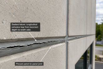
Sealant selection adds another layer of complexity that aluminum-derived practice does not resolve. Sealant joint widths are typically sized to keep sealant strain within the manufacturer’s rated movement capability, usually expressed as a percentage of joint width.
If the joint was sized for aluminum movement and the installed panel moves 40 to 50 percent more, the sealant is operating outside its rated range from the first thermal cycle. Silicone sealants with high movement ratings can tolerate more abuse than polyurethane systems, but neither is a substitute for correctly sized joints.
The sealant selection conversation cannot happen productively until the thermal movement calculation has been done with the correct CTE values.
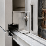
Attachment Mechanics: Where Fixed Points Become Failure Points
Proper FRP panel attachment requires the same fixed-point and floating-point discipline that governs metal panel systems, but the execution tolerance is tighter and the consequences of getting it wrong are faster to appear. Each panel needs exactly one fixed point controlling the origin of thermal movement.
Every other fastener location must allow bidirectional movement through slotted holes sized to the actual calculated panel expansion. This is not a recommendation.
It is a mechanical requirement for a material with this CTE range.
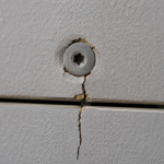
Bearing stress at fastener holes is a critical limit state that FRP’s material properties make genuinely difficult to manage. The interlaminar shear strength of common FRP laminates is low relative to aluminum and oversized holes, improperly torqued fasteners or inadequate edge distances can initiate delamination at the attachment zone well before any surface failure is visible.
The failure initiates at the fiber-matrix interface under the fastener head and progresses inward.
Pull-through and pull-out values for FRP are laminate-dependent and must be established by test, not by analogy to aluminum or high-pressure laminate. ETAG 034, the European Technical Approval Guideline for Kits for External Wall Cladding, provides the most rigorous available testing framework for rainscreen cladding attachment.
It has not been adopted into IBC-based specifications. That gap leaves North American specifiers without a standardized protocol for establishing FRP fastener performance in a tested assembly configuration.
ASTM E488 covers fastener pull-out in substrate materials and is a useful supplementary reference, but it does not address the panel-side bearing and pull-through behavior that governs FRP attachment design.
Edge distance requirements for FRP are more demanding than for aluminum because the material’s resistance to bearing stress drops off sharply as the fastener approaches the panel edge. A minimum edge distance of three times the fastener diameter is a reasonable starting point for most glass-fiber laminates, but that value should be confirmed against test data for the specific laminate thickness and fiber architecture being used.
Field installations frequently violate this requirement because the attachment layout was developed for a different material and never recalculated. Installers working from aluminum panel details do not automatically recognize that the edge distance rules have changed.
Thermal cycling fatigue deserves specific attention. Repeated micromovement at fastener locations against a rigid substrate generates cumulative damage that static load testing under ASTM E330 does not capture.
A panel that passes structural testing on day one may be developing fatigue-initiated cracking at fastener holes by year three. The mechanism is straightforward: each thermal cycle produces a small amount of relative movement between the panel and the fastener shank.
Over hundreds or thousands of cycles, that movement abrades the hole perimeter and initiates matrix cracking that propagates along fiber-matrix interfaces. The process is invisible from the exterior until the damage has progressed far enough to affect panel geometry or allow water infiltration.
By that point, replacement is typically the only remediation option.
Washer selection and torque control are underspecified in most FRP attachment details. Oversized washers distribute bearing load across a larger area of laminate and reduce the risk of pull-through under wind loading.
Torque limits must be specified and enforced because FRP compresses under fastener head load in a way that aluminum does not and overtorqued fasteners crush the laminate locally, reducing the effective bearing area and accelerating fatigue damage. These are installation-level details that do not appear in generic specifications and are not volunteered by industrial FRP suppliers.
UV Degradation and Surface Delamination: The Slow Failure No One Inspects For
Unsaturated polyester and vinyl ester resin systems are the most common and lowest-cost FRP matrix materials in commercial panel applications. Both are susceptible to UV-initiated hydrolysis that progressively degrades the resin-fiber interface.
Surface gelcoat or a UV-stabilized topcoat is the primary defense. The problem is that longevity under facade conditions is rarely specified with measurable performance criteria.
“UV-stabilized” in a product data sheet is not a performance threshold. It is a marketing descriptor.
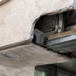
Delamination initiates at the surface ply and progresses inward. Early-stage delamination produces no visible signal from grade and is not captured by routine visual facade inspections.
By the time blistering or edge separation is visible, the affected area is substantially larger than what the surface shows. A panel that appears to have a localized blister at one corner may have subsurface delamination extending across a third of its area.
The only reliable way to detect early-stage delamination is through infrared thermography or acoustic tap testing, neither of which is part of standard building maintenance protocols for most commercial properties.
Gelcoat thickness is a variable that specification documents rarely address with precision. A gelcoat layer below 15 mils provides inadequate UV protection for exterior facade applications, particularly in high-solar climates.
Industrial FRP products are not consistently manufactured to facade-grade gelcoat specifications because their original market applications do not require it. A panel destined for a truck body or a chemical storage enclosure does not need to maintain color stability and surface adhesion through 20 years of south-facing solar exposure in a desert climate.
The facade application imposes requirements that the product’s manufacturing standards were never written to meet.
The combination of thermal cycling and UV degradation accelerates the failure timeline. As the resin matrix loses cohesion from UV exposure, the stresses generated by thermal movement concentrate at already-weakened fiber-matrix interfaces.
Fastener zones and panel edges are the first locations to show this combined effect because they experience the highest stress concentrations under thermal loading. A panel in year five of service on a south-facing facade in a high-UV climate may have surface resin degradation that has reduced its effective interlaminar shear strength by 20 to 30 percent relative to its original tested values.
The attachment detail that was marginally adequate at installation is no longer adequate under those degraded material properties.
Specifiers should require minimum performance thresholds for UV resistance using ASTM G154 for fluorescent UV lamp exposure or ASTM G155 for xenon arc exposure. Neither is routinely required in North American FRP facade specifications.
Acceptable performance thresholds, including gloss retention percentages, color delta-E limits and adhesion retention after exposure, must be explicitly written into the specification. Manufacturer data sheets do not volunteer failure thresholds.
Requiring 2,000 hours of exposure testing under ASTM G154 Cycle 1 conditions, with documented results submitted as part of the product submittal, is a reasonable and achievable standard. Manufacturers who cannot provide that data are signaling that their product has not been evaluated for facade service conditions.
What Third-Party Testing Should Cover: and Currently Doesn’t
Metal panel and high-pressure laminate systems specified for commercial facades routinely carry NFPA 285 fire test compliance documentation, ASTM E330 structural performance data across tested span and pressure combinations and manufacturer-backed warranty documentation tied to specific tested assemblies. FRP panels are frequently specified without any equivalent documentation package.
NFPA 285 compliance is not optional for panels installed over combustible insulation or within certain height thresholds under IBC Chapter 26. The test evaluates the entire assembly, not the panel in isolation. FRP panels have not been widely tested in NFPA 285 configurations and specifiers who assume compliance based on panel composition alone are taking a position that the AHJ may not accept.
The NFPA 285 test protocol requires a full-scale wall assembly mockup with the specific panel, insulation type, air barrier and framing configuration that will be used in the project. A passing result for one assembly configuration does not transfer to a different configuration, even if the panel product is identical.
When an FRP substitution is proposed after design development, the insulation type and air barrier system may already be specified and procured. If the FRP panel has not been tested in that specific assembly, NFPA 285 compliance cannot be claimed and the substitution cannot be approved for buildings where that compliance is required.
The structural testing gap is equally significant. ASTM E330 establishes uniform static air pressure testing for exterior windows, curtainwalls and cladding.
Specifiers should require test reports at project-specific design pressures, not generic manufacturer data developed for a different span and attachment configuration. When FRP is substituted after design development, this testing rarely gets revisited.
A test report showing adequate performance at a 4-foot span with a specific fastener pattern does not validate performance at a 6-foot span with a different fastener pattern, even if both use the same panel product. The structural behavior of a cladding panel is a function of the complete assembly geometry and test data must correspond to the actual installed configuration.
Impact resistance testing is another gap that FRP substitution reviews consistently overlook. ASTM E1996 governs missile impact resistance for exterior cladding in wind-borne debris regions and compliance is required under ASCE 7 and the IBC for projects in applicable wind zones.
FRP panels vary widely in their impact resistance depending on laminate construction and thickness and industrial products are not routinely tested to ASTM E1996 criteria. A panel that satisfies structural wind pressure requirements may fail missile impact testing and the two performance categories are not interchangeable.
Warranty documentation for FRP in facade applications is inconsistent at best. Industrial FRP manufacturers are not structured to provide the assembly-level warranty language that facade specifications typically require.
That structural mismatch between the product’s supply chain origin and the specification’s performance expectations is one of the clearest signals that FRP is being substituted into a context it was not designed to serve. A facade warranty that covers only the panel material and excludes attachment performance, joint integrity and long-term UV stability is not a facade warranty.
It is a product warranty that has been formatted to look like one.
Writing the Specification to Close the Gap
The absence of a dedicated facade standard for FRP does not mean specifiers are without tools. It means the specification itself has to do more work.
Several specific requirements belong in any FRP facade specification.
Require manufacturer-provided CTE test data per ASTM D696 for the specific laminate construction being supplied, in both the longitudinal and transverse directions. Do not accept generic FRP tables.
Require that joint widths and slotted hole dimensions be calculated from that tested data using the project’s design temperature range, not aluminum-derived defaults. The design temperature range should be established from ASHRAE 169 climate data for the project location, using the extreme high and low surface temperature values appropriate for the panel’s color and orientation, not ambient air temperature ranges.
Surface temperatures on dark-colored panels in high-solar climates can exceed ambient air temperature by 50 to 70 degrees Fahrenheit and that differential must be reflected in the movement calculation.
Require pull-through and pull-out testing per ETAG 034 or an equivalent protocol for the specific panel thickness and fastener type specified. Require that the attachment design be reviewed by a facade engineer who has confirmed the fixed-point and floating-point layout against the calculated movement values.
That review should produce a stamped calculation package, not a letter of general concurrence. The calculation package should identify the fixed-point location for each panel, the slot length and orientation at each floating fastener location and the minimum edge distances used in the design.
Require UV exposure testing per ASTM G154 or ASTM G155 with explicit pass/fail thresholds written into the specification: minimum 70% gloss retention, maximum delta-E of 3.0 after 2,000 hours of exposure and