

Aluminum Composite vs. Steel Soffit Panels: Risk Guide
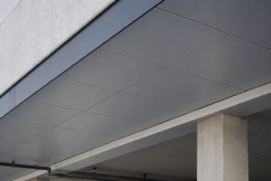
A parking structure soffit installation in the Pacific Northwest specified with standard aluminum composite material panels pulled directly from a vertical facade spec began delaminating within 18 months. Condensation pooled at panel seams.
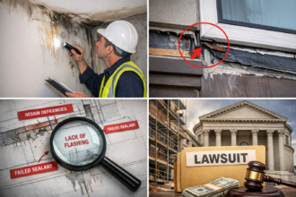
The project generated a six-figure warranty claim that the manufacturer denied, citing improper application category. The failure was not an installation error.
It was a specification error made at the material selection stage, before a single panel was hung.
That project is not an outlier. It is a pattern.
Why Soffit and Canopy Panels Are Not Vertical Facade Panels
Horizontal and near-horizontal orientations fundamentally change every moisture drainage assumption built into standard panel system engineering. Gravity-assisted drainage protects vertical rainscreen assemblies by moving water down and out of joints continuously.
At low slopes, that mechanism stops working. Water dwells, migrates laterally and enters seams under capillary action.
The same joint geometry that performs adequately on a vertical wall becomes a water collection point on a soffit.
Specifiers routinely copy vertical facade panel specs into soffit sections without adjusting for orientation-specific performance criteria. The panel product is identical.
The application category is not. Manufacturers write their warranties accordingly and AHJs are increasingly scrutinizing soffit assemblies under fire code provisions that have no vertical wall equivalent.
A 4mm ACM panel with a 10-year warranty on a vertical rainscreen carries that same 10-year warranty language into the soffit spec when copied without review, but the manufacturer’s warranty exclusions list horizontal applications separately. That exclusion is buried in the technical data sheet, not the product brochure.
ASTM E2128, the Standard Guide for Evaluating Water Leakage of Building Walls, applies primarily to vertical assemblies. No direct horizontal-surface equivalent exists at the same level of adoption.
That gap in the testing framework is itself a risk signal. When you specify a soffit system, you are operating in territory where standard diagnostic protocols were not written for your orientation.
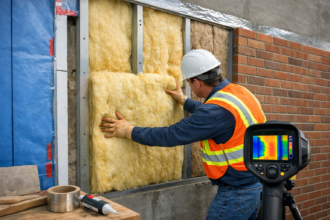
The closest analog, ASTM E1105 field water infiltration testing, can be adapted for overhead applications but requires custom test chamber fabrication that most field testing contractors are not equipped to provide. The result is that soffit assemblies frequently go unverified by any water infiltration test at all, even on projects where the vertical facade receives full ASTM E1105 testing at mock-up.
The two primary material candidates are aluminum composite material panels and fabricated steel panels. Each fails differently in soffit conditions.
Understanding those failure modes is the only basis for a defensible specification.
How Trapped Moisture Degrades Each Material Differently
ACM panel construction bonds aluminum face sheets to a polyethylene or fire-retardant core. That bond line is the vulnerability.
When moisture infiltrates panel edges in a soffit orientation, it cannot drain freely and it dwells at the adhesive interface. Core delamination follows.
The process accelerates because soffit assemblies cycle through condensation events that vertical assemblies rarely experience at the same frequency or duration. Field investigations of delaminated soffit ACM panels consistently show moisture staining and oxidation at the aluminum-to-core interface extending well beyond the visible delamination boundary, which means the damage area is always larger than the visible failure area.
Remediation scope routinely exceeds initial assessment by 30 to 50 percent once panels are removed.
Steel panels face a different failure mode. Galvanic and crevice corrosion initiate at lapped joints and fastener penetrations.
In coastal or high-humidity environments, those initiation sites become active within the first few years of service. The corrosion is not always visible immediately; it migrates beneath coatings before it breaks through to the panel face.
A steel soffit panel that looks acceptable at a five-year inspection may have active corrosion cells that have already consumed the zinc primer layer at lapped seams. By year eight, red rust bleed appears at the lap edges.
The building owner sees a sudden failure. The corrosion process started in year two.
The condensation mechanism driving both failure modes deserves explicit attention. Temperature differential between a conditioned interior and an exterior soffit surface creates a chronic wetting cycle on the underside of the panel assembly.
Standard warranty testing protocols do not replicate this condition. A panel product can pass every required test and still fail in soffit service because the test was never designed for that thermal exposure.
This is not a product quality problem. It is a test scope problem and specifiers who rely solely on test compliance as a proxy for application suitability are accepting a risk the test was never designed to address.
ASHRAE 160-2021 provides condensation risk thresholds relevant to metal panel cavity design. Its moisture-control design analysis criteria apply directly to the cavity conditions behind soffit panels, particularly in IECC Climate Zones 4 through 7 where interior-to-exterior temperature differentials are large enough to drive sustained condensation on cold panel surfaces.
In Climate Zone 6, for example, a parking structure soffit with an uninsulated concrete deck above and an exterior aluminum panel below can maintain surface temperatures below the dew point for six or more hours per day during winter months, a condition ASHRAE 160 flags as high condensation risk requiring active cavity ventilation or a continuous vapor control layer at the warm surface. Vapor retarder placement and ventilation gap requirements differ between ACM and steel assemblies.
Neither can be defaulted from a vertical wall specification. Both must be explicitly addressed for horizontal applications.
Fire Code Restrictions That Apply at Horizontal Surfaces
IBC 2021 Section 1402.6 addresses combustible cladding materials on exterior walls. What it does not do is automatically extend equivalent fire performance requirements to soffits and horizontal projections.
That gap creates false confidence. A specifier who confirms their ACM product complies with Section 1402.6 for a vertical facade has not confirmed compliance for the soffit of the same building.
The IBC treats soffits as part of the exterior wall assembly in some configurations and as a separate building element in others, depending on projection length and relationship to the exterior wall plane. That classification ambiguity means two AHJs reviewing the same drawing set can reach different conclusions about which code section governs and both can be technically defensible.
NFPA 285:2019 is a vertical test. The standard evaluates fire propagation characteristics of exterior non-load-bearing wall assemblies in a configuration that has no direct relationship to horizontal soffit geometry.
ACM products are frequently specified on soffit applications based solely on their NFPA 285 listing. That practice is technically unsupportable.
NFPA 285 compliance does not transfer to horizontal applications and no equivalent horizontal fire propagation test has achieved the same level of code adoption. The test apparatus orients the specimen vertically and measures flame propagation up the wall face and into the window opening.
That geometry tells you nothing about how the same assembly behaves when the panel is overhead and burning material can drip onto occupants or ignition sources below.
FM Approval Standard 4880 and UL 1040 address interior ceiling flame spread and are increasingly cited by authorities having jurisdiction for covered exterior soffit applications. The problem is that AHJ interpretation varies by jurisdiction and project type.
Specifiers must confirm directly which test protocol the local AHJ will accept before the specification is issued for bid. Discovering the AHJ’s position during permit review is too late.
On a recent transit canopy project in a mid-Atlantic jurisdiction, the AHJ required UL 1040 compliance for the soffit panels after the specification had already been issued for bid. The specified ACM product had no UL 1040 listing.
The substitution process added six weeks to the submittal schedule and required a re-bid of the panel scope.
Polyethylene-core ACM is explicitly restricted or prohibited in many jurisdictions at overhead exterior applications, even when the same product is permitted on vertical facades of the same building. The distinction follows from flame spread behavior: PE-core ACM in a horizontal overhead position presents a drip-and-spread ignition risk that vertical orientation does not.
FR-core ACM reduces but does not eliminate that risk. Confirming which core type your specification requires and confirming that the AHJ accepts it for the application category, are non-negotiable pre-specification steps.
Some jurisdictions have adopted local amendments that go further than the base IBC, prohibiting all ACM products at overhead exterior applications regardless of core type. California, New York City and several other high-density jurisdictions have issued interpretive guidance or local amendments that specifiers working in those markets must obtain and review independently of the model code.
Fastener and Connection Corrosion: The Risk Vertical Specs Ignore
Vertical facade fastener specifications typically assume transient water exposure. Soffit applications expose fasteners to sustained moisture contact and potential ponding at panel clips and sub-framing connections.
The assumption that a coated carbon steel fastener performing adequately on a vertical wall will perform adequately on a soffit is wrong. The exposure categories are not equivalent.
A coated carbon steel screw on a vertical wall sheds water within seconds of a rain event ending. The same screw on a soffit retains a moisture film at the head-to-panel interface for hours, particularly in shaded conditions where evaporation is slow.
The cumulative wet-contact hours over a five-year period are not comparable between the two orientations and coating performance degrades as a function of cumulative wet-contact time, not just peak exposure intensity.
Galvanic incompatibility between aluminum composite face sheets and steel sub-framing accelerates at horizontal surfaces where electrolytic moisture films persist between wetting events. This is a documented corrosion driver, not a theoretical one.
Dissimilar metal contact at clip connections and sub-framing attachments creates active corrosion cells that coating systems alone cannot suppress once moisture establishes a continuous film. The galvanic series places aluminum and carbon steel far enough apart in electromotive potential that even brief electrolytic contact drives measurable material loss.
At a soffit clip bearing directly on an aluminum panel return without an isolating washer, active corrosion can pit through a 0.040-inch aluminum face sheet in under three years in a high-humidity environment.
Steel soffit panels introduce a different fastener risk. Coating holidays at screw penetrations create initiation sites for red rust that migrate visibly across panel faces, generating aesthetic failures well before structural ones.
The panel may retain its load-carrying capacity while appearing to fail. That distinction does not help the building owner facing a facade remediation claim.
Self-drilling fasteners applied to pre-coated steel panels cut through the coating at the penetration point. Unless a sealant-backed washer is specified and installed correctly, that cut edge is bare metal in direct contact with overhead moisture.
Field observation on steel soffit panels at five-year intervals consistently shows rust migration patterns radiating from fastener locations, confirming that the penetration is the primary initiation site in the absence of sealant-backed washers.
Minimum fastener specification for soffit applications should require 316 stainless steel at coastal exposures, non-conductive isolators at all aluminum-to-steel contact points and sealant-backed fastener washers at every overhead penetration. AAMA 501.2 provides diagnostic relevance to fastener leak paths in installed assemblies, though its primary application is storefronts and curtain walls.
ASTM B117 salt spray testing thresholds for coating systems provide the baseline for evaluating fastener and clip coating performance; specify minimum salt spray hours in the contract documents, not just coating type. For soffit applications in non-coastal environments, a minimum of 1,000 hours salt spray resistance for fastener coatings is a defensible baseline.
Coastal applications should require 2,000 hours minimum, which effectively mandates 316 stainless or equivalent corrosion-resistant alloy fasteners because coated carbon steel cannot reliably achieve that threshold in overhead moisture conditions.
ACM and Steel Performance Across Three Soffit Environments
Environment selection drives material selection. Specifying without defining the exposure environment produces a defensible-looking specification that fails in the field.
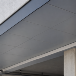
In a covered parking structure soffit, the exposure conditions are severe: high condensation cycling, vehicle exhaust acidifying surface moisture and de-icing salt migrating upward through drainage and evaporation. Steel panels with high-performance PVDF coating generally outperform PE-core ACM in this environment.
PVDF finish systems maintain adhesion and color stability under acid and chloride exposure better than the polyethylene core maintains its bond line integrity under chronic wetting. FR-core ACM is viable in this environment, but only with proper edge sealing at all panel perimeters and a ventilated cavity detail that allows moisture to escape rather than accumulate.
The ventilation gap behind soffit panels in parking structures must be sized to account for the reduced buoyancy-driven airflow in horizontal cavities; a 1-inch gap that provides adequate ventilation on a vertical rainscreen may be insufficient on a soffit where convective air movement is minimal. A minimum 2-inch clear cavity with open ventilation at both the wall-side and the free edge of the soffit is the standard detail for this application type.
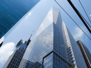
Building entry canopies in urban non-coastal environments present moderate moisture exposure with high aesthetic visibility and close AHJ scrutiny on overhead combustible materials. FR-core ACM performs well here if panel gauge and edge detail are specified correctly.
Steel offers longer finish warranty cycles in this application, typically 30-year PVDF finish warranties versus 10-year warranties common on ACM products, but steel requires more careful coordination of fastener coating compatibility and more attention to coating continuity at fabrication cuts. Entry canopies also receive more frequent cleaning than parking structure soffits and cleaning chemistry matters: alkaline cleaners attack PVDF coatings on steel panels and accelerate edge corrosion on ACM panels.
The maintenance specification should identify approved cleaning agents by pH range and prohibit pressure washing at panel joints, a practice that forces water into seams under conditions the joint sealant was not designed to resist.
Coastal and high-humidity facade overhangs represent the most demanding condition. Salt-laden air, sustained relative humidity above 80 percent and UV intensity combine to attack both material systems.
For both ACM and steel in this environment, 316 stainless fasteners are mandatory, not a best-practice recommendation. Steel requires a zinc-rich primer plus PVDF topcoat applied to fabricated panel dimensions, not to raw coil stock that gets cut in the field.
Field cuts through a coil-applied coating expose bare metal at the cut edge and in a coastal soffit environment that edge begins corroding within the first wet season. ACM requires marine-grade sealant at all panel edges and a documented re-sealing interval in the maintenance plan.
Silicone sealants rated for marine exposure and UV resistance, with a minimum 20-year service life per manufacturer data, are the appropriate product class for this application. Polyurethane sealants commonly used on vertical facades degrade faster under the combined UV and moisture exposure of a coastal soffit and should not be substituted.
Specifying the Right Assembly: What the Documents Must Say
A specification that names the material but omits the application category is an incomplete specification. For soffit and canopy panel assemblies, the contract documents must address orientation explicitly, define the exposure environment using the categories above, specify core type for ACM products by name (PE-core or FR-core), require AHJ confirmation of fire test protocol acceptance before submittal and establish fastener material minimums by exposure zone.
The four control layers require explicit treatment in soffit assemblies. The water control layer at a soffit is not a drainage plane; it is a barrier, because gravity does not assist drainage.
That distinction changes the product selection and the detailing at every joint. A drainage mat or drainage board that performs as the water control layer on a vertical wall provides no functional benefit on a soffit; the water control layer must be a continuous membrane or a fully sealed panel joint system with no reliance on gravity to move water away from the assembly.
The air control layer must be continuous across the soffit-to-wall transition, a joint that vertical facade specifications routinely leave unaddressed. That transition is where air-transported moisture enters the soffit cavity and an unsealed soffit-to-wall joint can deliver more moisture to the cavity than all other infiltration paths combined in a pressurized building.
The vapor control layer placement depends on climate zone and interior conditions; defaulting to “vapor barrier on the warm side” fails in mixed climates and produces condensation on the wrong surface. In Climate Zone 4 mixed-humid conditions, the correct vapor control layer placement for a soffit assembly over a conditioned space differs from the placement for the same assembly over an unconditioned parking level and the specification must address both conditions if both occur on the same project.
The thermal control layer at soffit sub-framing creates point thermal bridges at every clip location that the nominal R-value of any cavity insulation does not capture; effective R-value calculations must account for framing fraction and clip geometry. A soffit assembly with R-13 batt insulation between steel hat channels at 16 inches on center has an effective R-value closer to R-7 after accounting for thermal bridging through the framing, a reduction that changes the condensation risk profile significantly in cold climates.
The specification-to-field gap on soffit panels is wider than on vertical assemblies because the installer base has less accumulated experience with orientation-specific details. Pre-installation conferences should include a specific review of edge sealing sequence, fastener washer installation and cavity ventilation path confirmation.
Submittals should require the panel manufacturer to confirm in writing that the specified product is warranted for the application category as installed. That written confirmation is the document that resolves a warranty dispute in the specifier’s favor.
Without it, the manufacturer’s standard warranty exclusion for horizontal applications controls and the specifier carries the exposure.
The Claim You Are Trying to Avoid
The warranty denial in the Pacific Northwest project cited “improper application category. ” The manufacturer was technically correct.
The product was listed, tested and warranted for vertical facade use. Nothing in the specification required the manufacturer to extend that warranty to a soffit condition and nothing in the installation was wrong by vertical-wall standards.
That is the exposure specifiers carry when they copy and paste. The claim does not go to the installer.
It goes to the design professional. Six figures on a mid-size parking structure is a recoverable number.
The same specification error on a large mixed-use canopy assembly is not.
Confirm application category with the manufacturer in writing before the specification is issued. Get the AHJ’s fire test protocol acceptance in writing before permit submission.
Specify fastener materials by ASTM designation and exposure zone, not by generic coating description. These are not belt-and-suspenders precautions.
They are the minimum steps that separate a defensible specification from one that generates a claim you cannot win.