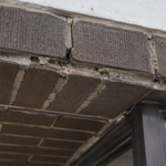
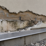
- A seven-year-old curtainwall suffered $2.3 million in remediation costs from a four-metal galvanic stack no specification section ever addressed as a system.
- Copper and zinc carry one of the most aggressive voltage potentials in common facade use at approximately 0.8 to 1.0 volts depending on electrolyte conditions.
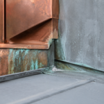
- Copper runoff contacting zinc panels below on the same drainage plane can initiate galvanic attack without any direct metal-to-metal contact between the two materials.
- MasterFormat’s division structure leaves no single trade responsible for the interfaces between Division 05, 07 and 08 creating compliant submittals that produce failing assemblies.
- A dissimilar metal compatibility matrix referenced in all three divisions and required before shop drawing approval is the specification tool that closes this gap.
Copper and Zinc in the Same Facade: The Galvanic Stack Nobody Specified
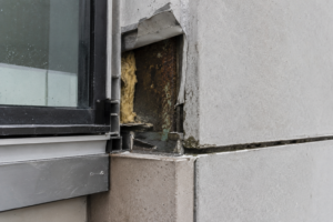
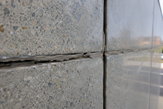
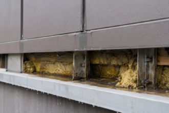
A forensic investigation on a seven-year-old mixed-metal curtainwall in the Pacific Northwest revealed accelerating white corrosion product weeping from behind zinc composite panels at every sub-girt connection point. Not from the panels themselves.
From the aluminum extrusions in direct contact with stainless fasteners seated against a steel embed. The failure had been attributed to “water infiltration” for three years before a building envelope consultant identified the actual mechanism: a four-metal galvanic stack that no single specification section had ever addressed as a system.
By the time liability was sorted across the cladding subcontractor, the glazing contractor and the structural steel fabricator, remediation cost had exceeded $2.3 million on a building still under its original facade warranty.
That is not an unusual story. It is a repeating one.
Why Galvanic Corrosion Keeps Surprising Specifiers Who Should Know Better
Galvanic corrosion is not new science. The electrochemical principles have been understood since the nineteenth century.
What is new is the complexity of contemporary facade assemblies and the speed at which mixed-material systems have proliferated relative to how slowly specification practice adapts to address them.
The core problem is jurisdictional. Division 05 owns structural steel.
Division 07 owns flashing, waterproofing and the water control layer. Division 08 owns glazing systems and curtainwall.
No division owns the interface between them. Each section references dissimilar metal compatibility in isolation, if it references it at all, without requiring cross-section coordination or a unified compatibility matrix for the full attachment stack.
Specifier reliance on manufacturer warranties compounds this. Most warranties explicitly exclude damage caused by contact with dissimilar metals not supplied by that manufacturer.
The warranty language looks like coverage. It is not.
ASTM G82, the foundational guide for developing and applying a galvanic series to predict corrosion performance, is rarely cited in facade specifications despite being the standard that should anchor every dissimilar metal compatibility requirement in the project manual.
What makes this particularly difficult to correct is that the failure timeline works against early detection. Galvanic corrosion in facade assemblies typically operates over a three-to-ten-year horizon before visible symptoms appear.
That timeline exceeds the construction administration phase, often exceeds the subcontractor’s warranty period and frequently outlasts the tenure of the project architect at the firm that designed the building. By the time the building owner sees staining or panel distortion, the design team has moved on and the specification record requires forensic reconstruction.
The institutional knowledge that might have caught the compatibility problem during design is no longer connected to the building. Specification practice needs to account for this lag by building in requirements that survive the project team’s departure, which means enforceable contract deliverables rather than design intent language.
The Galvanic Series in Plain Terms: What Copper, Zinc, Aluminum and Steel Actually Do to Each Other
The electrochemical nobility hierarchy relevant to common facade metals runs roughly as follows: copper sits at the noble end, stainless steel in passive condition sits near copper, carbon steel falls in the middle range, aluminum follows and zinc sits at the active anodic end. The less noble metal in any pairing corrodes sacrificially.
In a copper-zinc pairing, zinc is destroyed. In an aluminum-copper pairing, aluminum is destroyed.
This is not a matter of degree. It is the mechanism.
The voltage potential separation between copper and zinc in the galvanic series is approximately 0.8 to 1. 0 volts depending on electrolyte conditions.
That is among the most aggressive pairings in common facade use. Specifiers who understand the principle often underestimate the magnitude.
The area ratio problem makes this worse. A small anode connected to a large cathode accelerates corrosion dramatically because the anodic current density concentrates on a small sacrificial surface.
A single copper fastener penetrating a zinc panel creates a far more destructive condition than the reverse configuration. ASTM B117 salt spray testing, which is the accelerated corrosion test most commonly specified in facade sections, does not validate galvanic mechanism behavior.
It tests general corrosion resistance. Specifying ASTM B117 compliance for a zinc panel system and calling it corrosion protection is a category error.
Understanding the electrolyte requirement is equally important. Galvanic corrosion requires a conductive electrolyte bridging the two metals.
In facade assemblies, that electrolyte is almost always water, either bulk water from rain infiltration or thin-film condensation at the interface. This means that assemblies performing acceptably in dry climates can fail rapidly when the same detail is replicated in a marine or high-humidity environment.
A facade specification that was developed for a project in Phoenix and reused without modification on a project in Seattle has a fundamentally different risk profile at every dissimilar metal interface, even if every material specification is identical. Climate zone is not a footnote to galvanic compatibility analysis.
It is a primary variable. ASTM G50 atmospheric corrosion testing and the ISO 9223 corrosivity classification system both provide frameworks for calibrating expected corrosion rates to specific environmental conditions and both are almost entirely absent from facade project manuals.
Mapping the Attachment Stack: Where the Interfaces Actually Live
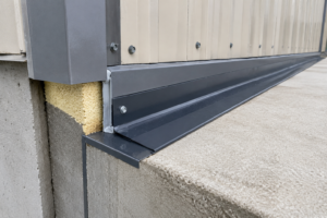
The typical mixed-metal facade attachment stack moves through several distinct material transitions. A structural steel embed anchored into the concrete structure receives a carbon steel or stainless steel anchor bracket.
That bracket supports an aluminum sub-girt or hat channel. Fasteners connecting the sub-girt to the bracket may be stainless, zinc-plated or aluminum depending on who specified them and whether the subcontractor substituted during procurement.
The cladding panel at the exterior face may be zinc, copper, aluminum composite or coated steel.
Each material transition in that stack is a potential galvanic interface. The four highest-risk locations are the anchor-to-embed connection, the fastener-to-sub-girt penetration, the sub-girt-to-panel interface and flashing laps where dissimilar metals overlap under compression.
SMACNA’s Architectural Sheet Metal Manual addresses dissimilar metal separation at laps and provides guidance that most facade specifications ignore entirely.
Runoff contact is a separate and underappreciated risk vector. Copper-rich runoff from copper cladding or copper-containing coatings contacting zinc or aluminum surfaces below creates galvanic attack without any direct metal-to-metal contact.
No isolation tape or gasket addresses this condition. AAMA 501 series curtainwall performance testing protocols do not include a galvanic-specific protocol, which means a curtainwall system can pass standard performance testing and still be on a ten-year path to galvanic failure.
The fastener is the most frequently overlooked interface because fastener specification is routinely delegated to the subcontractor and never coordinated with the cladding material specification.
What the stack diagram rarely shows is the role of field substitution in changing the galvanic character of the assembly. A subcontractor who substitutes zinc-plated screws for stainless at the sub-girt-to-bracket connection because they are cheaper and available from the same supplier has just introduced a new anodic element into a stack that was never analyzed with that material present.
The substitution is not flagged in the submittal review because fastener material is often not explicitly called out in the submittal package. The RFI process does not catch it because no one asked the question.
The result is an assembly that was designed with one galvanic profile and built with another. Requiring fastener material to be explicitly identified by alloy designation, not just by generic type, in every submittal that involves a metal-to-metal connection is a straightforward specification requirement that closes this gap.
It is rarely written that way.
Copper and Zinc: The Highest-Risk Pairing in Contemporary Facade Practice
Copper and zinc appear together on premium commercial facades with regularity because both materials are specified for aesthetic longevity. Architects specify zinc panels for their self-patinating gray finish and copper for its warm tone and long-term oxidation character.
They end up on the same elevation, on adjacent bays or in the same assembly with shared drainage planes. The aesthetic logic is sound.
The electrochemical consequence is not managed.
The specific failure modes follow a predictable sequence. Zinc panel corrosion initiates at fastener penetrations where stainless or copper-containing hardware contacts the panel face or edge.
Dezincification of brass components in contact with copper flashing removes zinc from the alloy matrix and leaves a porous copper sponge that has lost structural integrity while appearing intact. White zinc oxide staining appears at panel edges and joints before any structural section loss is visible.
By the time staining is noticed, the corrosion process has been running for months or years.
The runoff scenario deserves specific attention. Copper patina runoff carries cupric ions in solution.
When that solution contacts zinc panels or zinc-coated steel sub-girts positioned below the copper cladding on the same facade, it deposits copper ions onto the zinc surface and initiates galvanic attack through electrodeposition. The International Zinc Association’s technical guidance on copper-zinc incompatibility identifies this mechanism explicitly and recommends that zinc and copper never share the same drainage plane regardless of whether physical separation exists between them.
In humid or coastal environments corresponding to IECC Climate Zones 4C, 5 and marine-classified zones, visible zinc corrosion from copper runoff contact has been documented in peer-reviewed forensic literature within 18 to 36 months of installation. ASTM G31 immersion corrosion testing provides the laboratory validation methodology for quantifying this interaction rate, though it is almost never specified in facade project manuals.
NACE International (now AMPP) corrosion engineering literature on bimetallic corrosion rates in architectural applications provides field-correlated data that should inform specification requirements on any project combining these materials.
The dezincification failure mode warrants additional attention because it is the one most likely to be misread in the field. A brass fitting, compression sleeve or decorative element that has undergone dezincification retains its original geometry and surface appearance for a significant portion of its service life.
The copper matrix left behind after zinc removal looks like metal. It holds its shape.
It does not announce its degraded condition through visible distortion or obvious surface loss the way that white zinc oxide staining does on a panel face. A field inspector or building maintenance technician examining a facade assembly will not identify dezincified brass components without probing or laboratory analysis.
This means that the structural failure of a dezincified component, a fitting that fractures under wind load or thermal movement, arrives without warning. Specifying brass components in any location where copper flashing or copper cladding drainage can reach them is a decision that should require explicit engineering review, not a default material selection.
What the Specifications Are Missing: A Gap Analysis Across Division 05, 07 and 08
A typical Division 05 structural steel specification addresses corrosion protection through coating systems, hot-dip galvanizing per ASTM A123 and shop primer requirements. It does not address what happens when the galvanized embed contacts an aluminum bracket under sustained moisture exposure.
The galvanic relationship between zinc-coated steel and aluminum is not aggressive in most conditions, but introduce a copper fastener or copper-containing coating into that connection and the stack changes character entirely.
Division 07 flashing specifications typically require that dissimilar metals not be placed in direct contact and may reference separation by bituminous coating, isolation tape or plastic-faced sheet. This requirement appears in the flashing section and stops there.
It does not travel to Division 05 or Division 08. The subcontractors working those sections never see it.
Division 08 curtainwall and cladding specifications address the panel material and its finish system. They may include a warranty against corrosion of the panel itself.
They do not address the fastener specification, the sub-girt material or the flashing interface below the sill condition where copper-rich drainage from above will eventually reach zinc-coated components.
The gap is not ignorance. It is structure.
MasterFormat’s division architecture was not designed to manage cross-trade material compatibility. Closing this gap requires a project-specific dissimilar metal compatibility matrix, issued as a coordination document and referenced normatively in Division 05, 07 and 08 simultaneously.
Without that document, each trade installs a compliant assembly and the system fails at the interfaces between them.
The practical consequence of this structure is that the specification review process provides false assurance. A project architect reviewing Division 05 submittals against Division 05 requirements will find them compliant.
The same is true for Division 07 and Division 08 reviewed in isolation. Every submittal package passes.
Every material meets its specification. The assembly fails because the specification never addressed the assembly as a whole.
This is the condition that produces the $2.3 million remediation scenario described at the opening of this article and it is produced not by negligence but by a procurement and specification structure that treats the facade as a collection of independent scopes rather than an integrated system. The dissimilar metal compatibility matrix does not require a new division or a new trade.
It requires one coordination document that travels across all three divisions and makes the interface conditions explicit before the first shop drawing is submitted.
Isolation, Separation and Drainage: The Three Tools That Actually Work
Physical isolation between dissimilar metals requires a non-conductive barrier that maintains continuity under compression, thermal cycling and long-term service. Neoprene or EPDM isolation pads at bracket-to-embed connections and at sub-girt-to-panel interfaces are the standard approach.
The failure mode of this approach is installation: isolation pads that are compressed beyond their thickness tolerance, bridged by fastener washers or simply omitted by a field crew that does not understand why they matter.
Separation by drainage plane design is more reliable than isolation alone because it does not depend on installation precision at every fastener location. Designing the facade so that copper cladding and copper flashing drain away from zinc or aluminum components below eliminates the runoff contact vector entirely.
This is a design decision, not a specification requirement. It has to happen at the schematic level.
Specifying compatible fastener materials is the third tool and the most frequently botched. Stainless steel fasteners are compatible with aluminum sub-girts in most conditions.
They are not compatible with zinc panels at penetrations in wet environments. Silicon bronze fasteners are compatible with copper but incompatible with aluminum.
The fastener specification has to be material-specific to the interface it is connecting, not generic to the assembly type.
The installation dependency of isolation systems deserves more attention than it typically receives in specification language. Writing “provide isolation pad at all dissimilar metal contacts” is not a sufficient requirement.
The specification needs to define the minimum pad thickness after compression, the durometer range for the elastomer, the washer diameter relative to fastener shank diameter to prevent metal bridging and the inspection requirement that confirms pad presence before the connection is closed. Without those parameters, the isolation requirement is a design intent statement, not an enforceable installation standard.
Special inspection requirements under IBC Chapter 17 can be extended to cover dissimilar metal isolation at structural connections and doing so creates a third-party verification record that survives the construction phase. Most projects do not write the special inspection scope to include this check.
Adding it costs almost nothing at the specification stage and creates significant protection against the undetected installation failures that initiate long-term galvanic damage.
The Coordination Requirement That Every Mixed-Metal Facade Needs
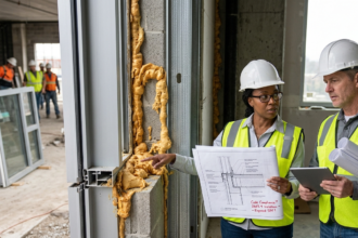
The building envelope consultant reviewing shop drawings on a mixed-metal facade has one job that the specification almost never gives them the tools to do: evaluate the complete attachment stack as a system rather than reviewing each trade’s submittals in isolation.
Require a dissimilar metal compatibility matrix as a contract deliverable. Make it the responsibility of the facade contractor of record, not the individual subcontractors.
Reference ASTM G82 in the specification as the standard against which compatibility claims are evaluated. Require that the matrix be submitted before any shop drawing approval and that it identify every metal-to-metal interface in the attachment stack from embed to panel face, including fastener materials at each layer.
The buildings failing today were specified by competent people who reviewed compliant submittals from qualified subcontractors. The failure was in the gap between the submittals, not in any single document.
Close the gap before the shop drawings arrive, because by the time you are reviewing submittals, the material decisions that will determine the outcome are already made.
The matrix requirement also changes the conversation with subcontractors during procurement. When a facade contractor knows that a compatibility matrix is a contract deliverable required before shop drawing approval, material selection decisions get made earlier and get made with the full stack in view.
A subcontractor who might otherwise default to zinc-plated fasteners because they are on hand will ask the question before ordering rather than after installation. The matrix functions as a coordination forcing mechanism, not just a documentation requirement.
Pairing it with a pre-installation meeting that brings the Division 05, 07 and 08 subcontractors into the same room to walk through the matrix together creates the cross-trade communication that the specification structure does not otherwise produce. That meeting, documented in the project record, also establishes shared awareness of the compatibility requirements that can matter significantly if a failure occurs and liability needs to be allocated.
The cost of that meeting is measured in hours. The cost of not having it can be measured in seven figures.