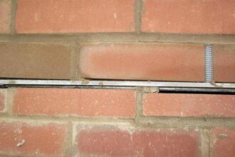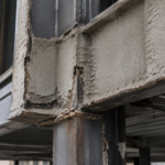
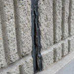
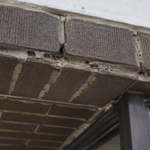
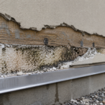
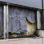
- Textured brick soffits invert normal drainage logic, causing moisture to dwell against mortar joints rather than drain away from them.
- Surface texture actively wicks water along the full joint length, increasing wetted area and extending drying time between freeze-thaw cycles.
- Standard five-year visual inspections can miss joints that have lost 60 to 70 percent of their bond integrity before visible cracking appears.
- Buildings in Climate Zones 5 through 7 may have cycled through 3,500 freeze-thaw events over 35 years with no quantitative baseline on record.
- Defensible soffit assessments require systematic grid-based probe testing, direct overhead access and documented baseline measurements for future comparison.
Textured Brick Soffits: Why Mortar Joints Fail Faster
During a routine five-year condition assessment of a 1989 mixed-use mid-rise in Minneapolis, a consultant probing a textured brick soffit with a pocket knife discovered that what appeared to be surface staining was actually a 40mm-deep mortar void running continuously across three courses. Invisible from grade, undetected in the previous inspection report and located directly above a covered pedestrian entry.
The discovery triggered an emergency shoring order and a liability review that traced back to an inspection protocol designed for smooth-face brick, applied without modification to a textured soffit assembly. That sequence of events is not unusual.
It is a pattern.
Why Soffit Brick Is a Different Animal Than Wall Brick
Gravity orientation is the first problem. Wall brick relies on drainage logic: water contacts the face, sheets downward and exits at weeps or flashing.
A soffit assembly inverts that logic entirely. Water that contacts a soffit face has no natural exit path.
It dwells against the mortar joint, migrates inward by capillary action and accumulates at the bond line rather than draining away from it. Every hour of dwell time is an hour of potential absorption.
The specification history compounds this. In 1980s and 1990s commercial construction, soffit brick was routinely specified as a continuation of the adjacent wall condition: same unit, same mortar, same joint profile, no soffit-specific detailing.
Contractors built what was drawn. What was drawn was a wall assembly rotated 90 degrees, with no acknowledgment that the performance demands had changed.
Project manuals from that era frequently referenced a single brick specification section covering all exposed masonry on the building, with no carve-out for soffit conditions. The result was that units selected for their appearance on a vertical wall face ended up installed overhead with no additional scrutiny of their absorption characteristics or joint compatibility in that orientation.
Thermal exposure on soffits also differs from walls. Direct solar drying is reduced or absent.
Humidity from below-grade parking structures, retail plinths and mechanical rooms vents upward through slab penetrations and expansion joints, loading the soffit environment with moisture that wall conditions never see. A covered pedestrian entry soffit over a retail podium, for example, receives moisture input from the occupied interior below, from precipitation driven horizontally under the canopy edge and from condensation cycling driven by the temperature differential between the heated interior slab and the cold exterior soffit face.
That combination of moisture sources has no equivalent on the wall face above it.
ASTM C216 (Standard Specification for Facing Brick) classifies units by grade and type but does not address texture classification as a performance variable in soffit applications. Grade SW (Severe Weathering) establishes minimum absorption and saturation coefficient thresholds for the unit itself, but those thresholds were developed against wall exposure data.
That gap matters. It means specifiers selecting units for soffit conditions have no ASTM framework that distinguishes a sand-finish unit from a smooth-face unit in terms of expected joint performance under sustained moisture exposure.
A unit that meets SW grade requirements on its unit absorption metrics can still produce accelerated joint failure in soffit orientation if its surface texture drives moisture concentration at the joint interface in ways the grade classification does not capture.
How Textured Faces Concentrate Moisture Differently Than Smooth Faces
Surface texture is not a cosmetic variable in a soffit assembly. It is a moisture management variable and it works against joint durability in ways that smooth-face units do not.
Ridges, grooves and sand-finish faces create capillary channels that actively wick water toward the mortar joint interface. A smooth-face unit sheds water across its face and concentrates moisture at the joint only at the direct point of contact.
A textured unit distributes moisture laterally along the full joint length through surface capillary action, effectively increasing the wetted joint area per rain event or condensation cycle. The joint is not just getting wetter at one point; it is getting wetter along its entire exposed length simultaneously.
In a running bond pattern with standard 10mm joints, a single textured unit face presents four joint segments to the soffit environment. Each of those segments receives moisture input from the full width of the unit face rather than from the joint width alone.
Texture also retains particulate contamination. Biological growth, airborne salts and construction residue lodge in surface irregularities and act as a hygroscopic reservoir.
That reservoir extends the duration of moisture presence at the joint face even after ambient humidity drops. A smooth-face unit dries in hours after a rain event.
A heavily textured unit in a low-solar soffit environment may not fully dry between events during a Minneapolis November. Lichen and algae colonies, common on north-facing and overhead masonry in humid climates, add a biological retention layer on top of the physical texture.
Those colonies are not merely cosmetic indicators; they are active moisture management problems that extend wetting duration and introduce organic acids that attack mortar binders over time.
BIA Technical Note 7 (Water Resistance of Brick Masonry: Design and Detailing) addresses capillary absorption principles for wall conditions. Applying that framework to an inverted soffit geometry reveals the problem directly: the mechanisms BIA describes for resisting water entry on a wall face become mechanisms for retaining water at a soffit face.
The assembly geometry converts a drainage asset into a detention liability. BIA Technical Note 7A extends those principles to flashing and drainage design, but again in the context of wall assemblies.
Neither document addresses the specific condition of a textured face in overhead orientation where gravity works against every drainage and drying assumption embedded in the guidance.
ASTM C67 (Standard Test Methods for Sampling and Testing Brick and Structural Clay Tile) includes initial rate of absorption (IRA) testing as a proxy for unit absorption behavior. The limitation for soffit performance prediction is significant: IRA is measured on bed faces, not on textured exposed faces.
A unit can pass IRA requirements comfortably while its textured face exhibits absorption characteristics that accelerate joint wetting in soffit orientation. That data gap has no current resolution in published literature.
Practitioners assessing existing textured soffit assemblies are working without a directly applicable absorption metric. One practical field workaround some consultants have adopted is conducting informal water drop tests on representative unit faces removed from the assembly, timing absorption against a smooth-face control unit from the same building.
That approach is not standardized and produces qualitative rather than quantitative data, but it gives the assessor a direct comparison that no published test method currently provides.
The Freeze-Thaw Mechanism at the Mortar-Unit Interface
The failure sequence is progressive and self-accelerating. Moisture accumulates at the textured face, migrates into the mortar joint by capillary action and saturates the outer zone of the joint.
When temperatures drop below freezing, that moisture expands by approximately 9% as it converts to ice. That expansion generates tensile stress at the mortar-unit bond line.
The bond line cracks. The crack volume increases the void available for moisture accumulation in the next wet cycle.
Each cycle enlarges the void. The joint does not fail at once; it fails incrementally and the rate of deterioration accelerates as void volume grows.
Soffit orientation concentrates this damage at the outer mortar face rather than distributing it through the joint depth. The outer face is both the primary moisture entry point and the first zone to reach freezing temperature during a cold event.
The result is a characteristic face-shell spalling pattern that differs from wall joint deterioration. Wall joints tend to show full-depth erosion over time.
Soffit joints show progressive outer-face delamination, with intact material behind the failure zone, until the bond line fails completely and the unit separates. That intact material behind the failure zone is precisely what makes the condition deceptive during visual inspection.
The joint appears to have depth and substance from an oblique viewing angle, while the actual bond line has already fractured across a significant portion of its area.
The mortar mix history of 1980s and 1990s construction adds another layer of risk. Pre-blended mortar products were less consistently specified in that era and field-batched mortar with variable water-cement ratios was common on commercial projects.
High water-cement ratio mortar produces higher porosity in the cured joint, which increases the volume of freezable water the joint can hold. A joint batched wet in the field to improve workability on a hot day may have a porosity profile meaningfully worse than the specification intended, with no record of that deviation surviving in the project documentation.
Thirty-five years later, the assessor has no way to reconstruct the actual mortar mix history from field observation alone.
Buildings in ASHRAE Climate Zones 5 through 7 (covering the Upper Midwest, Great Lakes region and Canadian Prairie markets where 1980s and 1990s commercial stock is concentrated) experience 40 to over 100 freeze-thaw cycles annually at the building envelope. A building that has been in service for 35 years in Minneapolis has potentially cycled through 2,800 to 3,500 individual freeze-thaw events at its soffit mortar joints.
That cycle count is not evenly distributed across the building. South-facing soffits over heated entries experience more daily cycling during shoulder seasons than north-facing soffits that stay frozen for extended periods.
The south-facing condition, counterintuitively, often shows more advanced deterioration because it cycles through freeze and thaw repeatedly within a single week rather than remaining in a sustained frozen state.
ASTM C1262 (Standard Test Method for Evaluating the Freeze-Thaw Durability of Dry-Cast Segmental Retaining Wall Units) is the closest published freeze-thaw cycling standard for masonry units. It does not apply to mortar joints and no equivalent standard exists for mortar joint assemblies in soffit orientation.
That absence is meaningful. ASTM C270 (Standard Specification for Mortar for Unit Masonry) establishes Type S and Type N compressive strength requirements and air-entrainment provisions, but it does not address freeze-thaw performance of the joint assembly in inverted geometry.
Type N mortar, sometimes specified in soffit conditions for workability, carries lower compressive strength and higher porosity than Type S. In a soffit assembly subject to 80 freeze-thaw cycles per year, that difference is not academic.
Air entrainment in mortar, addressed in C270 through the optional air content provisions, provides freeze-thaw resistance by creating distributed void space that accommodates ice expansion without generating bond-line stress. Whether the original mortar in a 1989 building included air entrainment is rarely documented and cannot be determined from field probe testing alone.
Core sampling and petrographic analysis can answer that question, but that level of investigation is rarely included in standard facade assessment scopes.
Why Standard Inspection Intervals Miss Progressive Joint Failure
Five-year facade inspection cycles are calibrated to visible surface deterioration on wall conditions. Textured soffit joint failure progresses internally before producing visible surface indicators.
A joint can lose 60 to 70% of its bond integrity before cracking or spalling becomes detectable from grade or from a standard swing-stage pass. The visual inspection protocol is not wrong for what it was designed to assess.
It is wrong for this application.
The Minneapolis case makes this concrete. The previous inspection report noted surface staining.
The staining was real. What the report missed was the 40mm void behind it, because the inspector was applying a visual survey methodology to a condition that required physical probe testing.
Those are not equivalent techniques. Sounding and probing reveal subsurface void development that visual surveys cannot detect in textured joint faces.
A coin tap or rod-sounding pass across a textured soffit joint produces an audible hollow response from a voided joint that looks intact from below. That technique requires direct overhead access and takes time, which is why it is routinely omitted from inspection scopes that were priced against a visual survey standard.
Inspection angle limitations compound the problem. Soffit conditions require direct overhead access for meaningful assessment.
Binocular surveys from grade, drone visual passes and swing-stage surveys conducted at face level all produce the same result: an oblique view of a textured surface that conceals rather than reveals joint void development. Lift equipment or rope access configured for direct overhead contact is the minimum standard for a defensible soffit condition assessment.
Drone technology has improved significantly in resolution and maneuverability, but a high-resolution image of a textured soffit face still cannot distinguish a surface crack from a through-joint void or identify the difference between a stained joint and a hollow one. Drones are a useful screening tool for identifying areas that warrant closer investigation.
They are not a substitute for contact-based assessment.
Documentation practice in existing inspection reports creates an additional problem. Reports for 1980s and 1990s buildings frequently lack baseline mortar joint depth measurements.
Without a baseline, quantifying deterioration rate between inspection cycles is impossible. The consultant performing the current assessment has no reference point.
Some jurisdictions with mandatory facade inspection programs, including New York City under Local Law 11 and Chicago under the Exterior Wall Inspection Program, require condition ratings but do not mandate quantitative mortar depth recording as a baseline metric. The result is a series of inspection reports that document condition at a point in time without generating the longitudinal data needed to identify acceleration in the deterioration rate.
ASTM E2270 (Standard Practice for Periodic Inspection of Building Facades for Unsafe Conditions) provides the framework most jurisdictions reference for facade inspection programs. Its provisions were developed primarily with wall conditions in mind.
Applying E2270 to textured soffit assemblies without supplementary probing protocols and direct overhead access requirements produces inspection reports that are technically compliant and operationally inadequate. E2270 defines unsafe conditions in terms of elements that present a falling hazard, which is the correct standard.
The gap is in the methodology prescribed for detecting those conditions before they become visible. A textured soffit joint that has lost 65% of its bond area meets the definition of an unsafe condition by any reasonable engineering standard, but it will not appear in a visual survey conducted under E2270 without the supplementary probing requirements that the standard does not currently mandate.
What a Defensible Soffit Assessment Actually Requires
The gap between a compliant inspection and a reliable one is widest in textured soffit conditions. Closing that gap requires three specific changes to standard practice.
First, probe testing on a systematic grid rather than selective probing at visible anomalies. For textured soffit assemblies on buildings over 20 years old in Climate Zones 5 through 7, a 1.5-meter grid spacing for probe testing is a reasonable starting point.
Visible anomalies warrant tighter spacing in the surrounding area. The Minneapolis void ran across three courses continuously; a single probe hit at the visible stain would have found it, but the inspection protocol never called for probing.
Grid-based probing also produces spatial data that selective probing cannot. A mapped grid of probe results across a soffit plane identifies deterioration patterns, including the directional spread of void development and the relationship between void location and moisture sources such as slab joints, pipe penetrations and canopy edge conditions.
That spatial pattern informs repair sequencing and helps the building owner understand whether the deterioration is localized or systemic.
Second, direct overhead access at representative locations. Representative means sampling each distinct soffit condition: covered entry conditions, parking structure soffits, canopy undersides and any location where interior humidity sources vent toward the soffit plane.
A drone pass or grade-level binocular survey does not substitute. Access planning for soffit assessments on mid-rise buildings typically requires coordination with building operations for lift equipment staging, which adds cost and scheduling complexity relative to a swing-stage wall survey.
That cost differential is real and should be addressed directly in the assessment scope rather than resolved by defaulting to a less appropriate access method. The cost of a scissor lift day and an additional field technician is a fraction of the cost of an emergency shoring order.
Third, baseline documentation of mortar joint depth and condition at the time of assessment, recorded in a format that allows quantitative comparison at the next inspection cycle. Photographs with scale references, probe depth measurements recorded by grid location and a condition map of the soffit plane.
Without that baseline, the next consultant is in the same position the Minneapolis team was in: no reference point, no rate of deterioration, no ability to predict when a marginal joint becomes a falling hazard. Baseline documentation also serves a direct liability function.
A consultant who records quantitative probe depth measurements at defined grid locations and returns five years later to find measurable increases in void depth has produced defensible evidence of deterioration rate. That evidence supports repair prioritization, budget forecasting and, if necessary, a legal record of the building condition at each inspection date.
The liability exposure on 1980s and 1990s soffit assemblies is not hypothetical. It is a function of age, climate exposure and the inspection methodology that has been applied to date.
Buildings that received visual-only inspections against a smooth-face protocol for 35 years are carrying unquantified risk. The question is not whether the joints have deteriorated.
They have. The question is how far the deterioration has progressed and whether the next freeze-thaw season is the one that produces a separation event above an occupied space.
Start probing. Document what you find.
Build the baseline now, because the consultant who inherits this building in five years will need it.