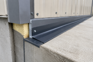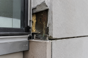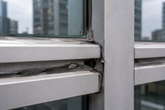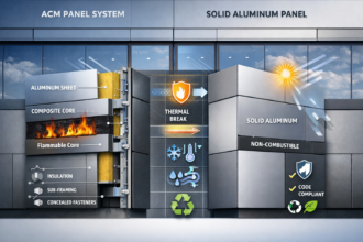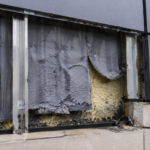
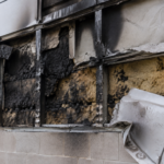
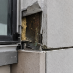
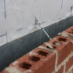
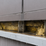
- Forensic investigations on buildings under 15 years old reveal welded aluminum subframe brackets developing fatigue cracks at heat-affected zones in high-movement zones.
- Aluminum expands at more than twice the rate of concrete, forcing bracket connections to absorb significant differential movement across thousands of thermal cycles.
- Welding 6061-T6 or 6063-T5 aluminum reduces base metal strength by 30 to 50 percent in the heat-affected zone, dramatically lowering fatigue life.
- Riveted connections in slotted holes distribute thermal movement without concentrating stress but require precise slot length calculations and field installation controls.
- Specifications that treat riveted and welded connections as interchangeable without zone-based movement analysis are creating the fatigue failures appearing in today’s forensic caseloads.
Riveted vs. Welded Aluminum Subframe: Fatigue Risk in Rainscreen Facades
A forensic investigation on a 12-story mixed-use building in Denver: completed in 2011: revealed that welded aluminum subframe bracket connections at south-facing high-movement zones had developed fatigue cracks at the heat-affected zones within nine years of installation, while riveted connections on the same elevation remained intact. The specification had treated both connection types as structurally equivalent, with no differentiation for thermal movement demand.
That single project framed a broader pattern now appearing in forensic caseloads across the Mountain West and Upper Midwest: buildings under fifteen years old showing structural fatigue at secondary attachment points that no one was looking for because the warranty period had already closed.
Aluminum Subframe Specifications Are Falling Behind Practice
Rapid adoption of aluminum subframe rainscreen systems in mid-rise commercial construction has outpaced specification development, particularly in ASHRAE Climate Zones 5 through 7 where thermal differentials are severe and cycling frequency is high. Most project specifications default to manufacturer standard details without requiring connection-type-specific structural analysis at high-movement zones.
The engineer of record stamps the facade package, the facade engineer reviews shop drawings against a performance specification and nobody explicitly invokes fatigue design criteria because the specification never asked for it.
Forensic investigators are now documenting fatigue-related attachment failures in buildings under fifteen years old. That timeline falls outside typical warranty and observation periods, which means owners are absorbing remediation costs with no contractual recourse.
AAMA 501.1 governs water penetration testing for curtain walls and does not address subframe fatigue at all. That gap between performance testing and structural durability evaluation is not an oversight in the standard; it reflects the original scope.
The problem is that project specifications treat passing AAMA 501.1 as confirmation of long-term structural adequacy. It is not.
The contractual structure of most facade projects reinforces this gap. The facade contractor is responsible for fabrication and installation per the approved shop drawings.
The facade engineer reviews shop drawings for conformance with the performance specification. The structural engineer of record reviews for primary structure loads.
Nobody in that chain owns the fatigue design of secondary subframe connections unless the specification explicitly assigns it. In practice, it rarely does.
Manufacturer standard details are developed for typical conditions and typical climates. They are not developed for the specific combination of member length, orientation, surface temperature and backup structure differential movement present on any given project.
Treating them as project-specific structural solutions is the specification error that produces the failure pattern forensic investigators are now cataloguing.
How Thermal Cycling Loads Actually Work in Aluminum Subframes
Aluminum expands at approximately 0.0000131 inches per inch per degree Fahrenheit. A 20-foot horizontal subframe member in Denver, subjected to a realistic 150°F differential between winter low and peak summer surface temperature on a south-facing dark cladding assembly, produces roughly 0.47 inches of linear movement per thermal cycle.
That number does not sound large. Multiply it by 1,000 to 2,000 significant thermal cycles over a 20-year service life and you have a fatigue loading scenario that demands explicit structural treatment.
Primary thermal movement runs longitudinally along the subframe member. Secondary movement is more complex: it represents differential displacement between the aluminum subframe and the backup structure, which may be concrete or steel with coefficients of thermal expansion that differ meaningfully from aluminum’s.
A concrete backup wall expands at roughly 0.0000055 inches per inch per degree Fahrenheit, less than half aluminum’s rate. That mismatch forces the attachment brackets to absorb differential movement that the subframe-to-cladding interface cannot resolve.
The magnitude of that differential displacement is not trivial. On a 20-foot concrete backup wall subjected to the same 150°F differential, the backup structure moves approximately 0.20 inches longitudinally while the aluminum subframe moves 0.
47 inches. The bracket connecting them must accommodate a net differential of roughly 0.27 inches per cycle.
At 1,500 cycles over a 20-year service life, that bracket has been displaced 0.27 inches and returned to neutral 1,500 times. If the connection is rigid, that displacement demand converts directly into stress at the connection.
If the connection is a welded bracket at a heat-affected zone with reduced material strength, the fatigue math resolves quickly and unfavorably.
ASCE 7-22 Section 1.3.1 requires that structures be designed for general structural integrity under all anticipated loading conditions, which includes cyclic thermal loading. The Aluminum Design Manual 2020 (ADM 2020) Chapter F governs fatigue design of aluminum members and connections explicitly.
Most facade subframe specifications do not invoke ADM 2020 fatigue provisions. That is not a minor omission.
It is the specification gap that produces the failure pattern described above.
The Metallurgical Case Against Welding at High-Movement Zones
Welding 6061-T6 or 6063-T5 aluminum reduces base metal tensile strength in the heat-affected zone by 30 to 50 percent compared to parent material. ADM 2020 Table A.
3. 4 quantifies weld-affected zone strength reduction factors for both alloys.
The T6 and T5 temper designations reflect precipitation hardening treatments applied after forming. Welding locally anneals the material, destroying that temper in the HAZ and leaving a zone of reduced strength that cannot be restored without full re-heat treatment of the assembly.
That is not practical in the field.
The specific fatigue failure mode at welded connections compounds the strength reduction problem. Stress concentration at the weld toe under cyclic loading initiates micro-cracking that propagates through the HAZ.
This is not a yielding failure or an overload failure. It is a fatigue failure, which means it occurs at stress levels well below the material’s nominal yield strength and produces no visible warning before the crack reaches critical length.
By the time a field inspector can see it, the connection has already lost structural integrity.
Rigid welded connections in high-movement zones make this worse. A welded bracket that cannot slip or rotate forces the entire thermal movement demand into the connection itself.
The subframe wants to move; the bracket resists; the HAZ absorbs the stress concentration at every cycle. AWS D1.2/D1.
2M classifies welded aluminum connections in cyclic loading applications in lower fatigue categories than equivalent steel connections, meaning they reach fatigue life limits at fewer cycles for the same applied stress range. Specifying a welded connection at a high-movement zone without invoking AWS D1.2/D1.
2M fatigue categories is not a conservative approach. It is an uninformed one.
The alloy selection compounds the problem further when specifications are not explicit. 6061-T6 is the most common structural aluminum alloy in subframe fabrication because of its availability and cost.
Its weld-affected zone tensile strength drops to approximately 24 ksi from a parent metal tensile strength of 42 ksi, a 43 percent reduction. 6063-T5, used frequently in extruded subframe profiles, drops from 27 ksi to approximately 17 ksi in the HAZ, a 37 percent reduction.
Neither alloy recovers strength at the HAZ without post-weld heat treatment. Specifications that call out alloy and temper for the base material but do not address weld-affected zone strength in the structural calculations are treating the connection as stronger than it physically is.
ADM 2020 Table A. 3.
4 exists precisely to prevent that error. Most facade specifications do not reference it.
The Mechanical Case for Riveted Connections and Their Own Failure Modes
Properly specified blind rivets in slotted holes create a controlled slip plane that accommodates thermal movement without concentrating stress at the fastener shank. The standard specification calls for 3/16-inch or 1/4-inch diameter rivets in 5056 or 7050 aluminum alloy, installed in slotted holes oriented parallel to the direction of thermal movement.
The rivet is set to allow controlled slip, not to create a fully clamped friction-dependent connection. That distinction matters enormously in the field, where installers default to driving fasteners tight unless the specification explicitly instructs otherwise.
AAMA TIR-A9 (Metal Curtain Wall Fasteners) provides rivet specification guidance and addresses fastener selection for aluminum subframe applications. It does not prescribe slot length calculation methodology for thermal movement demand.
That gap is the engineer’s responsibility to fill. Slot length must be calculated from the actual movement demand at each zone, accounting for member length, temperature differential and the coefficient of thermal expansion.
A slot that is too short converts a slip connection into a bearing connection at the end of the slot, which eliminates the fatigue benefit entirely.
The primary failure mode of riveted connections when incorrectly specified is hole elongation and bearing failure. This occurs when slotted holes are omitted, rivets are over-driven or movement demand exceeds slot length.
It is a progressive failure mode. The hole elongates visibly before the connection loses structural capacity, which gives inspectors an opportunity to catch the problem before it becomes a life-safety issue.
That is a meaningful advantage over HAZ cracking, which provides no visible warning. Riveted connections fail more slowly and more visibly.
That tradeoff is worth naming explicitly in specifications.
Field installation quality control is the other variable that specifications routinely underspecify for riveted connections. Blind rivet installation tools apply variable pull force depending on tool condition, operator technique and rivet lot variation.
A rivet set too tight in a slotted hole creates a friction-clamped condition that behaves like a fixed connection until the clamping force relaxes under thermal cycling, at which point the hole has already begun to elongate under the bearing loads the tight rivet generated. Specifying a pull mandrel force range, requiring periodic tool calibration checks and including a field mockup requirement for rivet installation at slotted holes are not extraordinary quality control measures.
They are the minimum controls needed to ensure the installed connection performs the way the structural calculation assumed it would. Most specifications include none of them.
Where Specifications Go Wrong: The Interchangeability Assumption
The specific specification language pattern that creates risk reads something like this: “connections shall be riveted or welded per manufacturer standard details. ” That language delegates a structural decision to an installer.
It treats riveted and welded connections as functionally equivalent alternatives, when they are structurally non-equivalent at high-movement zones.
The zone-differentiation principle should govern connection selection from the start of the specification process. Low-movement zones, including interior bays, short horizontal spans and north-facing elevations in Climate Zones 5 through 7, may tolerate welded connections if the structural analysis supports it and ADM 2020 fatigue provisions are satisfied.
High-movement zones, including long horizontal runs, south and west exposures and transitions between dissimilar backup structures, require riveted connections with slotted holes and explicit slot length calculations.
Shop drawing review is where this failure mode propagates undetected. Welded connections substituted for riveted connections during fabrication are difficult to identify in shop drawing review if the specification does not explicitly prohibit substitution at designated high-movement zones.
The shop drawing shows a bracket; the reviewer checks dimensions and material callouts; nobody flags the connection type change because the specification permitted it. Forensic cases consistently show that failure locations map directly to zones where thermal movement demand was highest and where the specification permitted connection-type substitution without structural review.
The specification created the condition. The installer executed it faithfully.
The substitution problem is not limited to fabricators making cost-driven decisions. It also occurs when the facade contractor’s detailer applies a standard bracket detail from a previous project without reviewing the movement zone map for the current one.
Without a zone map in the contract documents that explicitly ties connection type to location, the detailer has no basis for making a different decision. The zone map is not a supplementary document.
It is a primary structural deliverable that most current specifications do not require. Adding it to the submittal requirements, alongside the thermal movement calculations that support it, closes the specification-to-field gap that forensic investigators keep finding at the root of these failures.
What the Structural Analysis Should Actually Include
A structurally adequate subframe specification for a high-thermal-differential climate requires three things that most current specifications omit. First, a thermal movement demand calculation for each zone, based on member length, orientation, surface color, climate data and coefficient of thermal expansion for both the subframe and the backup structure.
Second, an explicit connection-type assignment for each zone, with welded connections prohibited at zones where movement demand exceeds the fatigue capacity of the weld category per AWS D1.2/D1. 2M.
Third, slot length calculations for all riveted connections at high-movement zones, with field installation instructions that specify rivet set force to prevent over-driving.
ADM 2020 Chapter F fatigue provisions should be invoked in the structural basis of design for any aluminum subframe system in Climate Zones 5 through 7. This is not a conservative overreach. It is the minimum technically defensible position for a 20-year service life on a mid-rise commercial building.
The ADM 2020 fatigue design approach requires identifying the fatigue category for each connection type, determining the number of anticipated stress cycles and checking that the calculated stress range at each connection does not exceed the allowable stress range for that fatigue category.
The fatigue category assignment step is where many engineers who do attempt fatigue design make errors of omission. ADM 2020 Table F.
8. 1 assigns fatigue categories A through F to aluminum connection details based on geometry and loading condition.
A welded bracket with a transverse fillet weld at the bracket-to-subframe interface falls into Category E or F depending on weld geometry, with allowable stress ranges at 500,000 cycles of approximately 2.0 to 3. 0 ksi.
A mechanically fastened connection in a slotted hole falls into a higher category with a correspondingly higher allowable stress range. The difference in allowable stress range between a welded and a properly configured riveted connection at the same location can exceed a factor of three.
That difference is not recoverable through material upsizing alone. It requires changing the connection type.
Specifying the correct connection type from the start of design is the only reliable path to a fatigue-adequate subframe in a high-movement zone.
None of this is prohibitively complex. It requires a facade engineer willing to do the calculation rather than deferring to manufacturer standard details.
The Denver building described at the opening of this article was not a specification failure caused by ignorance of the standards. It was a specification failure caused by not applying standards that existed and were available at the time of design.
The Forward Obligation for Facade Engineers
The forensic pattern is now clear enough to constitute a professional obligation. If you are specifying aluminum subframe connections for a rainscreen assembly in Climate Zones 5 through 7 on a south or west exposure with horizontal members longer than 12 feet and your specification does not differentiate connection types by movement zone, you are accepting structural risk on behalf of your client without disclosing it.
That is not a defensible position.
The correction is straightforward: zone the subframe drawing, calculate movement demand by zone, assign connection types accordingly and prohibit substitution at high-movement zones without engineer of record review. Require AWS D1.2/D1.
2M fatigue category documentation for any welded connection that remains in the design. Require slot length calculations as a submittal item for riveted connections at high-movement zones.
These are not extraordinary requirements. They are the minimum that the available structural standards support.
The professional liability dimension of this issue is sharpening as the forensic record accumulates. When a facade engineer in 2025 specifies interchangeable connection types on a south-facing aluminum subframe in Minneapolis or Denver without a movement zone analysis and that building develops fatigue failures at year twelve, the argument that fatigue design criteria were not standard practice will not hold.
The ADM 2020 fatigue provisions have been available since the 2000 edition of the Aluminum Design Manual. AWS D1.2/D1.
2M has addressed welded aluminum fatigue categories for decades. The standards exist.
The calculation methodology exists. The forensic record documenting what happens when they are not applied is now extensive enough to define the standard of care.
Buildings built today with interchangeable connection specifications will appear in forensic caseloads in 2035. The standard of care is moving. Specifications need to move with it.