


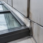


- A 3/8-inch undocumented gap at an IMP panel base caused frost heave, condensation and rodent entry at a cold-storage facility.
- The IMP base condition sits at the convergence of three trades with no single party holding explicit scope for the interface.
- ASHRAE 90.1-2022 makes slab edge insulation a code compliance requirement in Climate Zones 4 through 8, not a best practice.
- Correct detailing requires four components in sequence: slab edge insulation, base flashing, foam core closure and air barrier termination.
- A pre-installation conference with signed trade acknowledgments converts sequencing requirements into enforceable contractual obligations.
Sealed IMP Base Conditions: Detail the Slab Edge Right
A cold-storage facility in the upper Midwest, completed 18 months prior, presents with recurring frost heave at the base of wall, visible condensation tracking along the slab edge and rodent entry at three panel bays. All of it traces back to a 3/8-inch gap between the panel foam core and the slab edge flashing that no subcontractor documented, no inspector flagged and no warranty covers.
The general contractor is holding retainage from the IMP installer. The IMP installer is pointing to the concrete subcontractor’s slab tolerance.
The flashing contractor was never formally scoped for this interface. This is not an isolated incident.
It is the default outcome when base-of-wall detailing is treated as a coordination footnote rather than a primary envelope condition.
Why the IMP Base Condition Is the Assembly’s Weakest Link
IMP systems are increasingly specified for their thermal continuity and speed of enclosure. The marketing case writes itself: factory-assembled panels, predictable R-values, single-trade installation.
But manufacturer details typically terminate at the slab line and defer to “field conditions,” which is a polite way of saying the most consequential transition in the assembly is left to whoever shows up last with a caulk gun.
The base condition sits at the convergence of three trades: the IMP installer, the concrete or slab contractor and the flashing or sheet metal contractor. No single party holds explicit scope for the interface between them.
That gap in accountability produces the gap in the assembly.
Unlike the head or jamb conditions, the base must simultaneously manage all four control layers: air sealing, bulk water drainage, thermal continuity at the slab edge and pest exclusion. These four performance requirements pull the detail geometry in different directions.
A back-dam flashing that drains bulk water creates a ledge that traps debris and compresses sealant. A tight foam closure that stops pest entry can block drainage if the panel shifts.
ASHRAE 90.1-2022 Section 5. 4 makes slab edge insulation a compliance requirement in IECC Climate Zones 4 through 8, not a best-practice recommendation.
That code driver makes the base condition a legal liability, not just a performance aspiration. When the base detail fails thermally, the building fails continuous insulation compliance.
The consequences compound over time: interior humidity loads increase, insulation degrades and code-compliance gaps widen.
What makes this condition particularly difficult to manage is that the failure is invisible at the time it is created. The base trim covers the foam core gap.
The exterior base angle covers the slab edge insulation discontinuity. The interior finish covers the air barrier termination.
By the time the building is occupied and the failure manifests as condensation or frost, every component that caused it is behind another component. Forensic investigation at that point requires destructive opening of the assembly, which triggers the contract disputes described in the opening scenario.
The only cost-effective intervention point is the construction document.
Specifiers who have worked through base condition failures on prior projects consistently report the same finding: the detail existed on the drawings, but the specification language did not assign scope clearly enough to survive the subcontract division of work. The drawing showed the right geometry.
The spec said “coordinate with adjacent trades. ” No trade coordinated.
The geometry was not built. Writing the correct detail is necessary but not sufficient.
The specification must carry the detail into the field with explicit trade assignments and a sequencing requirement that makes out-of-order installation impossible to miss.
Understanding the Geometry: What Actually Happens at the Slab Edge
The physical stack-up matters before any detail gets drawn. In a typical tilt-up or steel-frame structure with a concrete slab-on-grade, the IMP panel bears on a steel base angle or shelf angle anchored to the foundation wall or slab edge.
The panel bottom rail sits on that bearing surface and the exterior skin of the panel projects past the slab face by some dimension that varies with the structural layout. The foam core sits between the interior and exterior steel skins, typically recessed 1/4 to 3/8 inch behind each face.
Once the base trim is installed over the exterior skin, that foam recess becomes invisible from both sides. The hidden void is the infiltration pathway, the pest highway and the thermal discontinuity, all in one location.
Here is the root cause of field improvisation: ACI 117-10, Section 4.8.1, specifies a formed slab edge tolerance of plus or minus 3/4 inch. That means the gap between the panel bottom rail and the slab face can vary by 1.5 inches across a single building.
No fixed-dimension detail handles that range without field modification. A detail drawn to a nominal 1-inch gap will be inadequate at 1.75 inches and over-compressed at 1/4 inch.
The spec must address tolerance accommodation explicitly or the installer will accommodate it with whatever backer material is on the truck.
Elevated slab conditions shift the performance hierarchy. On a slab-on-grade, drainage is the primary concern because groundwater and snowmelt are active threats at the base.
On an elevated slab, bulk water is less likely to enter from below, so air sealing and vapor management move to the top of the priority list. The detail geometry differs.
The spec language must reflect which condition applies.
The projection dimension of the exterior panel skin past the slab face also varies with structural framing layout. In a steel-frame building where the column line sits at the interior face of the panel, the panel may project 4 to 6 inches past the slab edge, creating a substantial cantilever of the exterior skin over open air.
In a tilt-up building where the panel bears directly on the footing, the projection may be minimal. Each configuration produces a different base angle geometry, a different flashing profile and a different foam closure dimension.
Treating these as the same detail produces failures in both cases, just different failures. The specifier must review the structural framing plan in relation to the panel layout before finalizing the base condition detail and that review must happen during design development, not during shop drawing review when the structural steel is already fabricated.
Slab camber adds another variable that manufacturer details never address. Post-tensioned slabs in particular can exhibit mid-span camber of 1/2 inch or more, which means the gap between the panel bottom rail and the slab face is not constant even across a single bay.
An installer setting panels to a fixed base angle elevation will see the gap open and close as the slab profile changes beneath them. Without a flexible closure system that accommodates that variation, the installer will either shim the base angle to follow the slab, which disrupts the flashing continuity or ignore the variation and leave gaps at the high points of the camber profile.
The Four Failure Modes: Air, Water, Thermal and Pest
Air infiltration at the base condition bypasses the panel’s tested air barrier continuity in a way that is easy to miss on paper. ASTM E2357-22 is the assembly-level air barrier test standard, but base termination conditions are a known exclusion in most tested assembly configurations.
The panel system earns its air leakage rating through the tested joint geometry between panels. The base condition is a field-fabricated transition that was never part of the tested assembly.
That creates a compliance gap between the performance number on the submittal and the performance of the installed building. The foam core recess and base trim gap create a direct air pathway that the tested assembly data does not account for.
In cold-storage applications, this air infiltration pathway carries warm, humid exterior air directly into the cold zone at the base of the wall. The dew point of that infiltrating air is reached almost immediately upon contact with the cold slab surface, producing condensation that saturates the slab edge insulation and migrates inward.
ASHRAE 90.1-2022 Appendix C provides infiltration calculation methods that assume a continuous air barrier. When the base condition is open, the actual infiltration rate at the base of a cold-storage wall can exceed the whole-building assumed rate by a factor of three or more at that localized zone, based on pressure differential testing conducted on similar facilities during forensic investigations.
Bulk water intrusion follows capillary geometry. Windblown rain and snowmelt enter the base trim cavity and wick inward along the slab surface if there is no positively sloped sill or back-dam flashing to redirect them.
The cavity between the exterior skin and the slab face acts as a collector, not a drain. Water that enters does not find a path out.
In freeze-thaw climates, that trapped water expands on freezing and exerts lateral pressure against the panel bottom rail and the slab edge, accelerating the gap that allowed entry in the first place. This is the mechanism behind the frost heave described in the opening scenario.
The water entered through the 3/8-inch foam core gap, saturated the slab edge zone, froze and expanded and widened the gap further with each thermal cycle. By the time the building owner called for investigation, the original 3/8-inch gap had grown to nearly 5/8 inch at two of the three affected bays.
Thermal bridging at the uninsulated slab edge interrupts the IMP’s continuous insulation value at precisely the location where the assembly is coldest. In cold-storage applications this drives condensation on interior slab surfaces within 12 to 18 inches of the wall.
The effective R-value of the assembly at the base drops to near-zero across the slab edge width, regardless of the nominal R-value of the panel above. THERM modeling of a typical 4-inch concrete slab edge without insulation in a Climate Zone 6 condition shows a linear thermal transmittance (psi value) of approximately 0.8 BTU/hr-ft-F, which represents a significant energy penalty concentrated in a 6-inch-wide zone that runs the full perimeter of the building.
Pest entry through the recessed foam core is documented and predictable. Foam-to-metal interfaces without sealant or mechanical closure are not considered a pest barrier under most state health codes for food-processing and cold-storage facilities.
Rodents exploit the recess because it is dark, protected from weather and thermally comfortable. The foam itself is not a deterrent.
Standard EPS and polyiso foam cores used in IMP panels offer no resistance to rodent gnawing. A mouse requires an opening of approximately 1/4 inch to gain entry.
The nominal foam core recess in most IMP panels is 1/4 to 3/8 inch before any field gap is added. The base condition, without a mechanical closure and sealant, meets the minimum entry requirement for rodent infiltration at the time of panel installation, before any gap widening from thermal cycling or frost heave occurs.
What the IMP Manufacturer Details Show and What They Don’t
Most major IMP manufacturers publish base condition details that address the exterior trim profile and fastener pattern. The details show the base angle, the panel bottom rail, the exterior base trim and the fastener spacing.
What they do not specify is the sealant type, the backer rod size or the closure material for the foam core gap. Those items appear as unlabeled voids in the section drawing or they are addressed with a generic note that reads “seal per manufacturer’s recommendation” without directing the reader to a specific recommendation document.
Manufacturer details are drawn to ideal slab geometry. They do not show tolerance accommodation.
They do not show flashing integration with the slab edge insulation system. They do not show the transition to whatever waterproofing or dampproofing is applied to the foundation wall below grade.
The detail is accurate for the condition it depicts and silent on every condition that actually occurs in the field.
This silence is not accidental. Manufacturers draw details that represent their product’s performance under controlled conditions.
They are not in a position to detail every site-specific transition and they are not liable for field conditions outside the panel system itself. That is a reasonable boundary for a product manufacturer.
It becomes a problem when the specifier treats the manufacturer’s detail as a complete design solution rather than a starting point that requires project-specific supplementation. The specifier’s role is to take the manufacturer’s panel detail and extend it to the adjacent conditions: the slab edge insulation, the base flashing, the air barrier termination and the pest closure.
If the project specification simply references the manufacturer’s standard detail and stops there, the specifier has documented the panel but not the building.
Shop drawing review is the last formal opportunity to catch the gap before installation. Facade engineers must know to look for it.
Most shop drawing checklists include panel joint sealant, panel orientation and fastener pattern. A base condition air seal line item is rarely on the list.
If the shop drawing shows the same unlabeled void that the manufacturer’s standard detail shows and the reviewer does not flag it, the void gets built. A shop drawing review comment that reads “confirm base condition foam closure and sealant per specification Section 07 42 13, Paragraph 3.4” takes 30 seconds to write and prevents the failure described in the opening of this article.
That comment requires the reviewer to know what Paragraph 3.4 should say, which requires the specifier to have written it in the first place.
The IMP warranty typically covers panel-to-panel joints and factory-applied coatings. The base condition interface is explicitly excluded in most warranty language as a field-fabricated condition.
That exclusion is not unreasonable. What is unreasonable is specifying a system without addressing the condition the warranty excludes.
When the warranty exclusion and the specification gap align at the same physical location, the building owner has no contractual remedy and no performance guarantee for the assembly’s most failure-prone transition. That outcome is predictable at the time of specification.
It is the specifier’s responsibility to close it.
The Correct Detail: Components, Sequence and Material Specification
Getting the base condition right requires specifying four components in sequence, with clear trade ownership for each.
The first component is slab edge insulation. Specify continuous rigid insulation at the slab edge before panel installation.
Minimum 2-inch XPS per ASTM C578 or polyiso per ASTM C1289, mechanically fastened or adhesively set to the slab face. This is the thermal bridge break required by ASHRAE 90.1-2022 Section 5.
4 in Climate Zones 4 through 8. It must be coordinated with the concrete contractor’s scope and installed before the base angle is set or the base angle will bear against it and compress it unevenly. Assign this scope explicitly in the project manual.
Do not assume the IMP installer will own it. In practice, slab edge insulation frequently falls between the concrete contractor’s scope, which ends at the formed slab edge and the IMP installer’s scope, which begins at the base angle.
The project manual must bridge that gap with a named trade assignment in Division 07 72 00 and a cross-reference in both the concrete and IMP specification sections. The insulation product must be specified with a compressive strength rating adequate to resist the bearing load from the base angle, typically 25 psi minimum for XPS in this application per ASTM C578 Type IV or higher.
The second component is the base flashing. Specify a formed sheet metal sill flashing in minimum 24-gauge galvanized steel or 0.040-inch aluminum, with a positive slope to the exterior (minimum 1/4 inch per foot) and a back-dam leg that turns up behind the panel bottom rail.
The back-dam height should exceed the maximum anticipated water head at the base, which in most slab-on-grade conditions means a minimum 1-inch vertical leg. This flashing is the sheet metal contractor’s scope.
Write it that way in the specification. The flashing must be fabricated with a drip edge at the exterior face to prevent water from wicking back under the flashing and onto the slab edge insulation.
Sealant between the flashing and the slab edge insulation face prevents capillary migration at that interface. The flashing termination at panel joints must be coordinated with the panel layout so that flashing end laps occur at panel joints, not at mid-panel locations where the lap would be inaccessible after panel installation.
The third component is the foam core closure. Specify a closed-cell backer rod sized to compress 25 to 50 percent against the foam core recess, followed by a low-modulus polyurethane or silicone sealant compatible with the panel coating.
The backer rod accommodates the tolerance variation that ACI 117-10 allows. Without it, sealant bridging a wide gap will fail in tension within two to three thermal cycles.
This is the IMP installer’s scope, performed after the base flashing is set. The sealant must be specified by generic type and ASTM standard, not by brand name alone and must be confirmed compatible with both the panel coating finish and the sheet metal flashing substrate.
A low-modulus sealant per ASTM C920, Type S, Grade NS, Class 25 or higher is the appropriate specification for this joint, given the thermal movement expected at the panel base across a full annual temperature cycle in Climate Zones 4 through 8.
The fourth component is the air barrier termination. The assembly’s air barrier must lap onto the base flashing and be mechanically fastened and sealed at the termination edge.
Fluid-applied air barriers applied to the interior face of the panel must extend to the base flashing and be sealed with a compatible transition membrane. This step is the one most frequently omitted because it requires coordination between the IMP installer and the air barrier applicator, two trades that rarely sequence their work together.
The specification must require a written sequencing plan from the IMP installer that identifies the air barrier termination step as a hold point, meaning panel base trim cannot be installed until the air barrier termination has been inspected and approved. That hold point converts a coordination aspiration into a contractual requirement with a defined inspection trigger.
Trade Coordination: Who Owns What and When
The sequencing of these four components determines whether the detail works. Slab edge insulation goes in before the base angle.
Base flashing goes in before panel installation. Foam core closure happens after panel installation but before base trim.
Air barrier termination happens before interior finishes close access to the base condition. Each step depends on the previous one being complete and correct.
The project specification must assign each component to a named trade with explicit scope language. “Coordinate with adjacent trades” is not scope language.
It is an instruction to argue later. The division of work in CSI MasterFormat terms typically places slab edge insulation in Division 07 72 00, base flashing in Division 07 62 00, panel installation in Division 07 42 13 and air barrier continuity in Division 07 27 00. Writing cross-references between these sections is the specifier’s responsibility.
If the sections do not reference each other, the trades will not coordinate.
The pre-installation conference is the field mechanism for converting the specification’s sequencing requirement into a shared understanding among the trades who will execute it. The conference agenda must include a walkthrough of the base condition sequence with all three trades present: the IMP installer, the sheet metal contractor and the air barrier applicator.
The general contractor’s superintendent must be present and must document the agreed sequence in the meeting minutes. That documentation creates the record that the sequence was communicated, which matters when a trade later claims they were not informed of a dependency.
The conference should also establish who is responsible for inspecting each step before the next trade proceeds and that inspection responsibility should be named in the specification, not left to the general contractor’s general superintendence obligation.
The RFI process will not save you here. By the time an RFI about the base condition reaches the design team, panels are being set and the slab edge insulation that should have gone in first is no longer accessible.
The detail must be resolved in the construction documents, not in the field. RFIs about base conditions that arrive during panel installation are almost always requests for permission to skip a step that is no longer constructible in the correct sequence.
The design team’s options at that point are to accept a remedial detail that is less effective than the specified detail, reject the substitution and require destructive correction or document the deviation and accept the performance risk. None of those options is acceptable.
The correct response is to have resolved the detail before the first panel was ordered, because the panel lead time is the last practical deadline for finalizing the base condition geometry.
What the Next Project Should Look Like
The base-of-wall condition in an IMP assembly is not a difficult detail. It is a neglected one.
The geometry is manageable, the materials are standard and the sequencing is logical once it is written down. The problem is that no one writes it down with enough specificity to survive the handoff between design intent and field execution.
The project that does this right will have a specification section that names the slab edge insulation product category and minimum thickness, assigns it to a trade and sequences it before base angle installation. It will have a shop drawing checklist that includes a base condition air seal line item, a foam core closure confirmation and a flashing integration note that requires the sheet metal contractor’s base flashing submittal to be cross-referenced against the IMP installer’s panel base detail before either submittal is approved.
Approving those submittals independently, without checking the interface between them, is how the unlabeled void in the manufacturer’s standard detail survives into the built assembly.
It will have a pre-installation conference agenda item that walks all three trades through the sequence together before the first panel is lifted. The conference record should include a signed acknowledgment from each trade that they understand their scope, the sequencing dependency and the hold point before base trim installation.
That signed record is not bureaucratic overhead. It is the document that determines liability when the base condition fails and the trades begin pointing at each other, as they did in the upper Midwest cold-storage facility that opened this article.
And it will have an inspector who knows to look for the foam core closure before the base trim goes on, because once that trim is fastened, the void is invisible and the failure clock starts. Special inspection for IMP base conditions is not standard practice on most projects.
It should be. The inspection effort required is minimal: a visual confirmation that the backer rod is in place, that the sealant has been applied and tooled and that the air barrier termination membrane laps onto the base flashing before the trim is fastened.
That inspection takes less time per bay than writing the RFI that will be generated when the failure appears 18 months later.
The 3/8-inch gap that generated 18 months of frost heave, condensation tracking and rodent entry was not a construction accident. It was a specification failure.
Write the detail. Assign the scope.
Sequence the trades. The gap does not have to be there.





Great information to pass on to the Field
Thanks
Lynn Harrison
General Superintendent