

Spray Polyurethane Foam at Exterior Wall Transitions: Air Sealing Performance Claims, Fire Code Restrictions and Where the Field-Applied Assumption Creates Code Compliance Risk
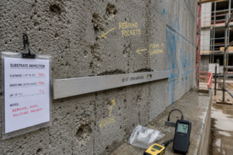
During a pre-occupancy air barrier commissioning walk on a mid-rise commercial project, a building envelope consultant discovers that every curtainwall-to-CMU transition, every window-to-sheathing rough opening and every penetration sleeve has been packed with open-cell SPF. Four different subcontractors applied it.
None of them pulled a fire code review or referenced a thermal barrier detail. The foam is exposed, uncoated and in several locations directly adjacent to interior occupied space with no intervening assembly.
The project is three weeks from certificate of occupancy. The owner’s attorney is already on speed dial.
This scenario is not hypothetical. I have walked it personally on three separate projects in the last five years.
The pattern is consistent: SPF fills the gap between what the detail shows and what the field actually builds and nobody asks whether the fire code permits that gap-filling strategy until a commissioning agent or an AHJ shows up with a clipboard.
The Field Default: How Spray Polyurethane Foam Became the Go-To Gap Filler at Exterior Wall Transitions
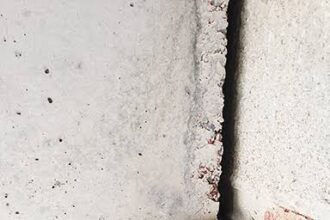
SPF’s conformability to irregular geometry, its adhesion to dissimilar substrates and its expansion into voids that no other material reaches make it practically irresistible at complex transitions. Curtainwall sill pockets, window rough openings and sheathing-to-structure gaps all present geometries that backer rod and sealant handle poorly.
SPF handles them effortlessly.
Air barrier continuity requirements under IECC 2021 Section C402.5.1.1 and ASHRAE 90. 1-2019 Section 5.4.3.1 have increased design pressure to seal transitions that were previously left loose or flashed only.
As energy code compliance has tightened, the field response has been to reach for the foam gun rather than redesign the transition detail.
Contractor-driven substitution is the norm. SPF appears at transitions without design team authorization, without submittal review and without any reference to the original specification.
The material’s dual marketing as both an air barrier and insulation reinforces the perception that it satisfies multiple code requirements simultaneously. That perception reduces scrutiny.
It should not. The air control layer and the thermal control layer have distinct performance requirements and a material that claims to serve both functions at a transition joint deserves more documentation, not less.
The economics of the substitution reinforce the behavior. A two-component SPF kit costs a fraction of a purpose-designed transition membrane system and the application time is measured in minutes rather than hours.
A window installer who has already hung forty units in a day is not going to stop and read a specification section about fluid-applied transition membranes. The foam can is already on the truck.
The decision is made before the specification is consulted, if it is consulted at all.
What makes this pattern particularly difficult to interrupt is that the initial result looks correct. Fresh SPF at a transition joint appears to fill the void completely, adheres visibly to both substrates and produces a surface that reads as continuous to anyone walking the floor.
The air barrier continuity that the energy code demands appears to be present. The problems that follow, whether from fire code noncompliance, joint movement or vapor drive, are invisible at the time of application and frequently remain invisible until a test or inspection forces the issue.
Reading the Fine Print: What SPF Air Barrier Certifications and Test Data Actually Certify
SPF products marketed as air barrier materials are typically tested to ASTM E2178, which measures air permeance of the cured material at 75 Pa. The threshold for classification as an air barrier material is 0.02 L/s·m² or less.
Many closed-cell SPF products meet this threshold comfortably. The problem is what that certification does not cover.
ASTM E2178 evaluates the cured material in isolation. It says nothing about performance at a transition joint under differential pressure, substrate movement or thermal cycling.
ASTM E283 evaluates air leakage through assemblies but similarly does not address joint movement cycling or long-term adhesion at dissimilar substrate interfaces. Neither standard was designed to certify SPF as a gap filler at curtainwall-to-masonry or fenestration-to-sheathing transitions.
Many SPF products carry Air Barrier Association of America listings. Those listings apply to the product as a continuously field-applied membrane, not as a backer or volumetric filler at dissimilar substrate transitions.
The ABAA listing criteria do not evaluate the transition joint condition.
Manufacturer technical data sheets tell the rest of the story if you read them. They routinely include language limiting warranty and performance claims to applications with a minimum applied thickness, a maximum joint width and a specific substrate preparation protocol.
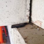
At a curtainwall sill pocket or a rough opening framed with multiple dissimilar materials, none of those conditions are reliably met.
The closed-cell versus open-cell distinction compounds the problem. Open-cell SPF has a vapor permeance that can exceed 10 perms at 3.5 inches, which disqualifies it as a vapor retarder in most climate zones and creates condensation risk at transition locations where the dew point falls within the assembly.
Field applicators routinely use open-cell where closed-cell was specified or assumed. Nobody checks.
The substrate preparation language buried in those data sheets deserves particular attention. Most SPF manufacturers require that substrates be clean, dry and free of frost, oil and release agents before application.
At a curtainwall sill pocket on an active construction site, those conditions are rarely verified. Concrete masonry units may be damp from recent grouting.
Steel framing members may carry mill oil or construction debris. The aluminum extrusions of a curtainwall system may have been handled with gloved hands that left contamination at the bond surface.
The foam adheres visually in all of these conditions, but the bond strength and long-term air barrier performance are compromised in ways that no field inspection will detect.
ASTM E2357, which evaluates air barrier assemblies under simulated wind pressure cycling, is the standard most directly relevant to transition performance and it is the standard most frequently cited in air barrier specifications. What practitioners often miss is that E2357 testing is conducted on specific assemblies with specific joint conditions.
A product that passes E2357 as part of a tested assembly does not carry that approval to a field condition that differs from the tested configuration. The tested assembly is the approval.
The field condition must match the tested assembly to invoke that approval legitimately.
The Thermal Barrier Requirement: The Fire Code Obligation That Field-Applied SPF Routinely Violates
IBC 2021 Section 2603.4 is the controlling provision. It requires that foam plastic insulation be separated from the interior of a building by a thermal barrier, typically 1/2-inch gypsum wallboard or an approved equivalent, unless the specific assembly has been tested and approved under IBC Section 2603.9 or a specific exception applies.
At exterior wall transitions, SPF is frequently applied in locations that are either directly exposed to interior occupied space or separated only by an air gap, a metal reveal or a non-rated substrate. None of those conditions satisfy the thermal barrier requirement.
A metal curtainwall frame is not a thermal barrier. A cavity between the foam and the interior finish is not a thermal barrier.
The “15-minute thermal barrier” concept is widely misunderstood. The requirement is not about the fire resistance rating of the wall assembly.
It is about protecting the foam from ignition and flame spread during the early stages of a fire event. Foam plastic ignites, burns rapidly and produces toxic combustion products.
The thermal barrier requirement exists because that behavior is unacceptable in an occupied building without protective separation.
Design teams rarely issue details that explicitly address thermal barrier compliance at transition conditions. The architectural detail shows the transition schematically: a line indicating foam, an arrow indicating continuity with the air barrier plane and nothing else.
The fire code obligation that requires a specific protective assembly at that same location lives in a different section of a different code document and the connection between the two is almost never made explicit in the construction documents.
NFPA 285 evaluates fire propagation through exterior wall assemblies but addresses the wall system as a whole, not the discrete transition condition. Passing NFPA 285 for the field-applied wall assembly does not automatically authorize exposed SPF at the curtainwall sill pocket.
The practical consequence of this documentation gap is that the fire code review happens, if it happens at all, during the shop drawing phase for the curtainwall system or the window wall system. The curtainwall contractor submits an NFPA 285 test report for the wall assembly.
The architect reviews it for the wall assembly. Nobody reviews it for the sill pocket condition, because the sill pocket condition is not shown in the curtainwall submittal and is not addressed in the architectural detail.
The fire code obligation at that specific location falls into a gap between submittals and the field fills the gap with foam.
Intumescent coatings tested under UL 1715 or UL 1040 offer one path to thermal barrier compliance without the bulk of gypsum board at tight transition conditions. Those coatings must be applied at the manufacturer’s required dry film thickness, which means the application requires measurement and documentation, not just a spray pass.
That documentation requirement alone is enough to distinguish a defensible installation from a field-improvised one.
Exception Misreading: How Contractors and Designers Incorrectly Invoke SPF Exemptions at Transition Locations
IBC 2021 Section 2603.4 includes exceptions for foam plastic used as a sealant or caulk in gaps not exceeding 1 inch. This exception is routinely cited to justify SPF application at transitions.
The misapplication is consistent and consequential.
The exception applies to small gap-filling applications. It does not apply to the volumetric filling of sill pockets, rough opening cavities or spandrel voids that measure 2 to 6 inches in cross-section.
When a subcontractor fills a 4-inch curtainwall sill pocket with open-cell SPF and cites the sealant exception, that citation fails. The exception was not written to accommodate spray-applied, expanding foam products used at large-format transition conditions.
The code language predates the widespread commercial use of two-component SPF at these locations.
Some installers and design teams rely on manufacturer-issued code compliance letters or FM approvals as blanket authorization. Those documents are not blanket authorizations.
An FM approval for a specific roofing assembly does not transfer to a wall transition condition. A code compliance letter that addresses SPF in a continuous wall application does not address SPF in an exposed sill pocket condition.
Reading those documents carefully reveals that the scope of approval is almost always narrower than the field application.
The AHJ is the final authority on exception interpretation. In my experience, AHJs in jurisdictions that have adopted IBC 2021 are increasingly familiar with the sealant exception’s scope limitations.
The projects that relied on a broad reading of that exception are the ones generating the litigation files.
The one-inch gap threshold in the exception is not a suggestion. It is a dimensional limit that defines the boundary of the exception’s applicability.
A gap that measures 1-1/8 inches falls outside the exception. A gap that varies between 3/4 inch and 1-1/2 inches along its length, which is a common condition at curtainwall-to-CMU interfaces where the masonry tolerance and the curtainwall tolerance stack, falls outside the exception at every location where it exceeds the threshold.
Field installers do not measure gap width before applying foam. They fill what is in front of them.
The exception analysis that would have required them to stop at 1 inch never happens.
The broader problem with exception reliance is that it shifts the compliance burden to the field without giving the field the information needed to make a correct determination. If the construction documents do not identify which transition conditions qualify for the sealant exception and which require a thermal barrier assembly, the installer has no basis for making that distinction.
The design team’s silence on the question is not authorization. It is an abdication of the documentation responsibility that the code places on the registered design professional.
What Happens to the Air Barrier When the Joint Moves
SPF is a rigid material once cured. Closed-cell SPF is more rigid; open-cell is more compressible but still lacks the elastic recovery of a purpose-formulated joint sealant.
At curtainwall-to-CMU transitions, differential movement between the curtainwall system and the masonry backup is a design condition, not an anomaly. Thermal movement, seismic drift allowances and long-term creep in the masonry all produce relative displacement at the transition joint.
A properly designed transition at this location uses a sealant with documented movement accommodation factor, typically plus or minus 25 to 50 percent depending on the product and the joint geometry. ASTM C719 characterizes sealant movement capability.
SPF carries no equivalent rating because it was not designed for dynamic joint conditions.
When the joint moves, SPF either debonds from one substrate, tears through the foam body or both. The air control layer fails at that location.
The failure is not visible from the interior and is rarely detected without a blower door test or infrared thermography. Projects that pass initial commissioning with SPF at transition joints frequently show degraded performance at the three-to-five year mark, when the cumulative movement cycles have compromised adhesion.
This is the tradeoff that nobody names at the design table: SPF is easy to apply and provides excellent initial air barrier performance, but it lacks the long-term movement accommodation that transition joints require. Ease of installation is not a substitute for joint design.
The numbers behind curtainwall thermal movement make this concrete. An aluminum curtainwall mullion spanning a typical floor-to-floor height of 13 feet will experience a temperature differential of 100 degrees Fahrenheit or more between summer peak and winter minimum in a climate zone 4 or 5 location.
The coefficient of thermal expansion for aluminum is approximately 0.0000131 inches per inch per degree Fahrenheit. Over a 156-inch span, that produces roughly 0.20 inches of movement at the sill condition.
A two-part SPF fill at that joint, even if it bonds perfectly to both the aluminum extrusion and the CMU backup at the time of application, is being asked to accommodate cyclic movement that it was never tested to handle. The debonding that follows is not a product failure.
It is a predictable consequence of applying a rigid material to a dynamic joint.
Fluid-applied transition membranes formulated specifically for dissimilar substrate joints address this condition directly. Products in this category are tested for elongation at break, typically exceeding 200 percent and for adhesion to aluminum, concrete masonry and gypsum sheathing.
They are applied in a controlled thickness, bridging the joint with a membrane that can accommodate the design movement without tearing or debonding. The application is more demanding than foam, but the long-term performance at a moving joint is not comparable.
The Specification-to-Field Gap and Who Owns the Risk
The specification gap at SPF transition conditions has a specific anatomy. The architect issues a detail that shows continuity of the air barrier at the transition.
The specification section for air barriers references ASTM E2357 compliance for the primary field-applied membrane. The transition condition is either not detailed or detailed schematically.
The foam plastic insulation section does not address transition applications. The fire stopping section addresses through-penetrations but not sill pocket conditions.
Four subcontractors read that set of documents and reach the same conclusion: fill the gap with foam. Each one assumes the other trades have addressed the fire code question.
Nobody has.
Responsibility in this scenario distributes badly. The design team has not documented thermal barrier compliance at the transition.
The general contractor has not coordinated the subcontractor scope. The foam installers have not pulled a fire code review.
The AHJ has not inspected the condition before it was covered. The commissioning agent finds it three weeks before certificate of occupancy.
The building envelope consultant in that position faces a remediation scope that is genuinely painful: access to every transition, documentation of every exposed foam condition, a code compliance path for each location and a thermal barrier solution that can be installed without demolishing the interior finish. On a mid-rise project, that is a six-figure problem.
The subcontractor coordination failure at the center of this scenario is structural, not accidental. On a typical mid-rise commercial project, the curtainwall contractor, the window installer, the air barrier applicator, the insulation contractor and the firestopping contractor are all separate entities with separate scopes, separate superintendents and separate submittal packages.
The transition condition between the curtainwall and the CMU backup wall sits at the boundary of at least three of those scopes simultaneously. Each subcontractor’s scope language describes their work stopping at the edge of the transition.
None of them own the transition itself. The general contractor’s coordination obligation covers schedule and sequencing, but rarely extends to a detailed review of whether the combined field conditions at a transition joint satisfy the fire code.
The design team’s role in this failure is not passive. When a detail shows a schematic line at a transition and labels it “air barrier continuous, see specification,” that note is doing no work.
It does not identify the material, the application method, the fire code compliance path or the thermal barrier assembly. It transfers a design obligation to the field without providing the information the field needs to execute it correctly.
The registered design professional who signs and seals that detail has not completed the design. They have deferred it.
What a Defensible Transition Detail Actually Requires
The path forward is not to abandon SPF at transitions. It is to use it within its documented scope and to address the fire code obligation explicitly in the construction documents.
At fenestration rough openings where the foam depth is less than 1 inch and the opening is covered by the window frame or a rated interior finish, the sealant exception under IBC 2021