Through-Wall Flashing at Shelf Angles: Why the Most Overlooked Detail in Masonry Veneer Facades Is Also the Most Litigated
Why Shelf Angle Flashing Fails More Often Than Any Other Masonry Detail
A forensic investigation on a 12-story steel-frame office building constructed in 2003 reveals that every shelf angle level: six floors of continuous brick veneer: has been leaking since year three of occupancy. The through-wall flashing was lapped in the wrong direction at every inside corner and the termination bar was never sealed to the backup wall.
The owner faces $4.2 million in remediation costs and the specifying architect’s professional liability carrier has already reserved the claim. This single detail, fewer than 18 inches of flashing assembly at each shelf angle, is the reason the building cannot be sold.
Shelf angles create a mandatory interruption in the drainage plane at every floor line. They are structurally unavoidable and hydrologically vulnerable by definition.
Unlike head joint flashing or window sill flashing, shelf angle through-wall flashing must simultaneously manage structural load transfer, thermal movement and water management. Those are competing demands and they drive detailing compromises that practitioners accept too readily.
The structural engineer sizes the angle for load. The architect details the flashing for water control.
The waterproofing subcontractor reads Division 07. The masonry contractor reads Division 04. No single party owns the complete assembly and that fragmentation is exactly where the failures begin.
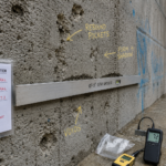
Forensic caseload data from firms including RDH Building Science consistently shows shelf angle flashing cited in 60 to 70 percent of anchored veneer water intrusion claims. ASTM E2128, the standard guide for evaluating water leakage of building walls, provides the investigative framework that surfaces this pattern repeatedly across building vintages and climate zones.
The standard’s systematic approach to identifying water entry paths, distinguishing primary from secondary failure modes and correlating damage patterns with specific assembly deficiencies makes it the most useful diagnostic tool available to the forensic investigator working a masonry veneer claim. Practitioners who have not read ASTM E2128 are operating without the vocabulary the litigation process will eventually impose on them.
The concealment problem compounds everything. Shelf angle assemblies disappear behind the veneer within weeks of installation, eliminating the window for visual verification before the damage cycle begins.
By the time water staining appears on interior finishes, the backup wall has typically been wet for years.
Anatomy of a Correct Through-Wall Flashing Assembly at a Shelf Angle
The correct assembly is not complicated. It is simply specified and executed incorrectly at a stunning rate.
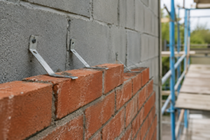
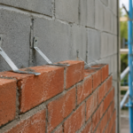
The flashing membrane adheres to the backup wall face, extends under the shelf angle bearing plate, turns up a minimum of 8 inches on the backup wall face and terminates with a surface-mounted termination bar fastened at 12 inches on center maximum, with sealant applied continuously between the bar and the membrane. The membrane extends outward through the veneer cavity and projects a minimum 3/8 inch beyond the face of the brick to form a functional drip edge.
The Brick Industry Association Technical Note 7 establishes the slope requirement: minimum 1/4 inch per foot toward the exterior face to direct water out rather than allow it to pond against the backup wall. On buildings where the shelf angle bearing plate is perfectly level, achieving that slope requires either a tapered mortar bed under the flashing or a membrane with a factory-formed slope.
Neither solution is complicated. Both require explicit specification language to actually appear in the field.
Weep integration is not optional. Open head joints at 24 inches on center maximum, positioned directly above the flashing plane, give collected water a path out.
Without them, the flashing becomes a bathtub. Rope wicks and plastic inserts are acceptable weep devices in low-exposure conditions, but open head joints remain the most reliable option in high-wind-driven-rain exposures because they cannot be blocked by mortar droppings the way insert-type weeps can.
The specification should identify which weep type is acceptable for the specific exposure condition of the project.
The relief joint below the shelf angle requires compressible filler, either backer rod or a closed-cell foam tape and a sealant that accommodates movement. This joint must remain open to drainage and free to move thermally.
It is not a caulk joint to be fully packed. Practitioners who treat it as a standard sealant joint create a new water trap while eliminating the expansion accommodation the assembly requires.
A fully packed relief joint that prevents thermal movement will crack the adjacent brick units within two to three heating and cooling cycles, opening new water entry paths that are far more difficult to seal than the original joint.
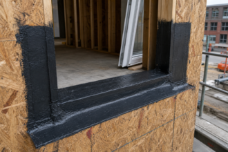
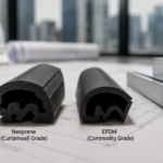
Material selection drives termination requirements. Self-adhered modified bitumen, EPDM sheet and liquid-applied membranes each behave differently at laps, corners and terminations.
Self-adhered modified bitumen is the most commonly specified option and performs well on smooth CMU and concrete backup walls when substrate temperature requirements are met during installation. EPDM sheet requires separate adhesive at laps and is more susceptible to fishmouth formation at inside corners when field-fabricated rather than prefabricated.
Liquid-applied membranes offer the best conformance to irregular substrates and complex geometry but require strict mil thickness verification and adequate cure time before the shelf angle is set. For CMU backup wall conditions, NCMA TEK 19-4A addresses substrate preparation requirements that directly affect membrane adhesion performance.
Specifying the membrane category without specifying the termination method for that specific membrane type is an incomplete specification.
The Four Most Common Detailing Failures and Why They Survive into Construction
These failures are not random. They repeat because the specification did not prevent them and the observation protocol did not catch them.
Inadequate upleg height is the most prevalent. Installers terminate the flashing membrane 2 to 3 inches above the shelf angle rather than the required 8-inch minimum.
Water migrates behind the membrane at the backup wall interface, saturates the substrate and enters the assembly without ever crossing the membrane face. The fix costs pennies per linear foot during installation.
The remediation costs tens of dollars per square foot after the veneer is removed. The reason this failure survives into construction is straightforward: the upleg height is invisible once the shelf angle bearing plate is set and most project observation protocols do not include a dedicated inspection window between flashing installation and shelf angle setting.
By the time anyone looks, the membrane is under the steel and the veneer is going up.
Improper lap sequencing at inside corners and splices is the failure that drove the $4.2 million claim described above. Laps installed shingle-fashion in the wrong direction relative to drainage flow create a direct water entry path at every splice.
The industry standard is a 6-inch minimum lap, fully adhered and sealed. When the specification omits the lap dimension and direction requirement, the installer defaults to whatever is fastest.
At inside corners, the correct sequence requires the field membrane to lap over the corner piece, not under it, because drainage flows away from the corner toward the field. Reversing that sequence at a single inside corner on each of six floors, as occurred in the building described above, means every inside corner on the building is a discrete water entry point.
There were 24 inside corners across the six shelf angle levels. Every one of them was wrong.
Missing or unsealed termination bar is the third pattern. The membrane is simply folded over the top of the shelf angle bearing plate with no mechanical attachment.
Wind-driven water at negative pressure differentials peels the membrane upward. IBC 2021 Section 1404.4 requires flashing at all horizontal surfaces subject to water infiltration, but it does not prescribe termination bar details.
That gap is where the failure lives. The code establishes the obligation to flash.
It does not describe what a complete flashing assembly looks like. Specifiers who cite IBC 1404.4 in their specifications without adding prescriptive assembly requirements have met the minimum legal threshold and left the contractor with no enforceable standard for termination bar installation.
The contractor will omit it because it takes time and the specification does not require it.
Flashing discontinuity at shelf angle anchor bolt penetrations is the fourth and most underappreciated failure mode. The membrane is field-cut around each bolt without collars, patches or liquid-applied reinforcement.
Each bolt becomes a discrete water entry point. On a typical floor line with shelf angle anchor bolts at 48 inches on center, a 200-foot building perimeter produces 50 unflashed penetrations per floor.
At six floors, that is 300 discrete water entry points that the flashing membrane was supposed to prevent. AAMA 711-13 establishes membrane performance benchmarks applicable to through-wall applications that provide useful guidance on penetration sealing requirements, even though the standard addresses fenestration flashing specifically.
The penetration sealing methodology it describes, liquid-applied reinforcement at the cut edge followed by a patch membrane extending 3 inches minimum in all directions from the penetration centerline, translates directly to anchor bolt conditions.
Specification Language That Actually Prevents These Failures
The coordination gap between Division 04 and Division 07 is where most shelf angle flashing failures originate in the contract documents. Masonry contractors read Division 04. Waterproofing subcontractors read Division 07.
When flashing requirements appear only in one location, the trade reading the other location has no contractual obligation to coordinate. Move the requirements into both divisions with explicit cross-references.
Section 04 20 00 should reference Section 07 27 00 for flashing membrane material requirements and installation standards. Section 07 27 00 should reference Section 04 20 00 for weep spacing, relief joint configuration and masonry coordination requirements.
Neither section is complete without the other and the specification should say so explicitly.
Prescriptive minimums must appear explicitly in the specification. The upleg height is 8 inches minimum.
The lap length is 6 inches minimum, fully adhered with no fishmouths or voids. The termination bar fastener spacing is 12 inches on center maximum.
The sealant type is non-sag polyurethane or silicone compatible with the specific membrane material. The drip edge projection is minimum 3/8 inch beyond the face of the veneer.
None of these values appear in IBC 2021 Section 1404.4. They must come from the specification. A specification that says “install flashing at shelf angles per manufacturer’s recommendations” has transferred the design decision to the membrane manufacturer’s generic installation guide, which does not address project-specific conditions, backup wall substrates or the interaction between the flashing assembly and the shelf angle bearing plate geometry.
Require a pre-installation submittals package that includes the membrane manufacturer’s written installation instructions, corner and splice fabrication shop drawings and a compatibility letter from the membrane manufacturer for all adjacent materials. This submittal requirement forces the conversation about corner fabrication before the crew is on the scaffold.
Corner fabrication shop drawings are the single most effective submittal for preventing lap sequencing failures because they require the installer to think through the drainage direction at every inside and outside corner before any membrane is cut. Installers who have fabricated correct corners once, with the shop drawing reviewed and approved, make far fewer sequencing errors in the field than installers who are figuring it out on the scaffold for the first time.
The single highest-use quality control requirement available to the specifier is a mandatory mock-up panel with water testing per ASTM E1105, adapted for masonry application. A tested mock-up, reviewed and approved before production installation begins, eliminates ambiguity about what a correct installation looks like.
Specifiers who skip the mock-up requirement because it adds cost to the schedule are accepting a much larger unknown risk in exchange for a known small saving. A mock-up panel that fails the ASTM E1105 test before production installation begins costs the contractor time and material to correct.
A failed assembly discovered during forensic investigation after the veneer is installed costs the owner the veneer, the flashing, the backup wall remediation and the interior finishes. The cost ratio is not close.
Construction Observation Protocols: What to Verify and When
Three mandatory observation windows define a defensible observation protocol for shelf angle flashing. Miss any one of them and the observation record is incomplete.
The first window opens after the backup wall is complete and flashing is installed but before the shelf angle is set. This is the only opportunity to verify upleg height, lap sequencing, corner fabrication and termination bar installation in accessible conditions.
Photographs at this stage are not optional. They are the evidentiary record that protects both the owner and the design professional if a claim emerges later.
Photograph the upleg height with a tape measure in frame. Photograph each inside and outside corner showing the lap direction.
Photograph the termination bar with sealant applied. These images, time-stamped and filed with the project record, are the difference between a defensible observation record and a claim that the design professional never verified the work.
On a building with six shelf angle levels, this observation window opens and closes six times. Each one requires a site visit and a photographic record.
The second window opens after the shelf angle is set and the bearing plate is in final position but before masonry veneer installation begins. Verify that the flashing membrane has not been displaced or punctured during shelf angle setting, that the relief joint filler is correctly positioned and that the weep system locations are marked and protected.
Shelf angle setting is a steel erection activity and steel erectors do not think about flashing membranes. Anchor bolt installation, bearing plate shimming and angle alignment all create opportunities to puncture, displace or contaminate the membrane.
A membrane that passed the first observation window can fail at the second if no one checks it after the steel is set. Any puncture found at this stage can be patched with liquid-applied membrane reinforcement at negligible cost.
The same puncture found during forensic investigation costs orders of magnitude more.
The third window is during veneer installation at each course above the flashing plane. Verify that open head joints for weeps are being maintained at the specified spacing and that mortar droppings are not bridging the relief joint below the shelf angle.
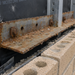
Mortar bridging in the relief joint is one of the most common causes of shelf angle corrosion and flashing damage in the first decade of service. Mortar dropped into the cavity during veneer installation collects on the shelf angle and in the relief joint, creating a continuous mortar bridge that transfers load across the joint, prevents thermal movement and holds moisture against the steel angle.
The result is accelerated corrosion of the shelf angle, cracking of the adjacent brick units and compression failure of the veneer at the relief joint line. All of it is preventable by verifying that the mason’s crew is keeping the relief joint clear during installation, which takes less than five minutes per floor during a site visit.
Observation is not inspection. The design professional’s site representative is not responsible for means and methods.
But the representative who never visits the shelf angle level during flashing installation has no basis for certifying substantial completion of that scope. Observation records showing zero visits during the flashing installation window have been used against design professionals in litigation.
Document what you saw, when you saw it and what corrective action was directed.
The Thermal Bridge Problem You Cannot Ignore
Shelf angles are continuous linear thermal bridges through the insulation plane. Every building envelope practitioner knows this.
What gets underweighted in practice is how the thermal bridge interacts with the water control layer performance.
In IECC Climate Zones 5 through 7, the shelf angle creates a cold surface on the interior side of the cavity wall assembly during heating season. If the through-wall flashing membrane is vapor-permeable and the backup wall assembly lacks adequate continuous insulation outboard of the air barrier, condensation can form at the shelf angle bearing surface and migrate behind the flashing membrane.
The water control layer failure and the thermal bridge failure are not independent events. They interact.
A membrane that is performing correctly as a water control layer can still experience adhesion failure at its bond line to the backup wall if repeated condensation cycles wet the substrate behind the membrane. The membrane does not leak.
The substrate behind it stays wet. The backup wall deteriorates.
The failure mode looks identical to a flashing installation deficiency and distinguishing between the two requires hygrothermal analysis of the assembly, not just a visual inspection of the membrane.
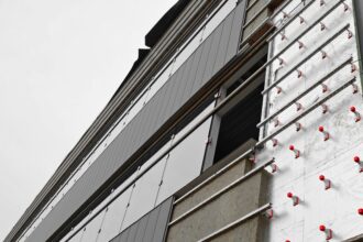
ASHRAE 90.1-2022 requires continuous insulation at shelf angles in these climate zones and the effective R-value of the assembly drops significantly at each shelf angle line due to the steel angle itself. Specifying 2 inches of mineral wool continuous insulation between the backup wall and the veneer achieves a nominal R-value of approximately R-8, but the effective R-value at the shelf angle line drops to R-2 or less depending on angle thickness and bearing plate configuration.
That cold zone is exactly where the flashing membrane is installed and where its adhesion performance is most critical. Some practitioners address this by specifying a thermally broken shelf angle system, using a structural thermal break pad between the backup wall framing and the shelf angle bearing plate.
These systems, offered by manufacturers including Halfen and Leviat, reduce the linear thermal transmittance at the shelf angle by 70 to 80 percent compared to a conventional welded or bolted connection. The cost premium is real.
So is the reduction in condensation risk at the flashing plane.
The interaction between thermal performance and water control layer performance also affects the choice of flashing membrane material. Self-adhered modified bitumen membranes can soften and lose adhesion at elevated temperatures and can become brittle at low temperatures.
In Climate Zone 6 and 7 applications where the shelf angle surface temperature can drop well below freezing during installation, membrane adhesion to the bearing plate and backup wall substrate requires careful attention to manufacturer-specified minimum application temperatures. A membrane installed at 20 degrees Fahrenheit on a steel bearing plate in a northern climate may appear correctly installed and fail its adhesion bond within the first heating season.
Design the thermal and water control layers as an integrated system at the shelf angle. They fail together when they are designed separately.
What the Next Generation of Masonry Veneer Failures Will Look Like
Buildings constructed