Insulated Metal Panels in Commercial Wall Assemblies: Where the Single-Skin Assumption Breaks Down
A cold-storage distribution facility in the upper Midwest passed visual inspection during construction closeout, then failed its whole-building blower door test at 0.4 CFM₅₀/ft². That result sits nearly double the ASHRAE 90.1-2019 threshold of 0.
25 CFM₅₀/ft² for commercial construction. The culprit was 1,400 linear feet of IMP horizontal joints sealed with field-applied backer rod and sealant left entirely to subcontractor discretion, with no engineered detail and no inspection hold point.
Remediation exceeded $180,000 before the certificate of occupancy could be issued. The panel system performed exactly as advertised.
The assembly failed because nobody designed the assembly.
Why IMP Systems Get Specified as Envelope Solutions and What That Promise Actually Covers
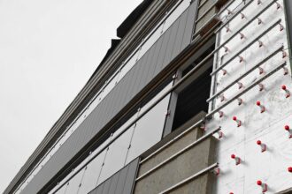
IMP manufacturers market their products as integrated wall systems combining structure, insulation, air barrier, vapor retarder and finish in a single product. That positioning is not dishonest.
It is incomplete. What manufacturers certify is panel body thermal performance expressed as R-value per inch of core and panel-level air permeance tested per ASTM E2178, the standard test method for air permeance of building materials.
Panel-level compliance with ASTM E2178 does not equal assembly-level compliance under ASHRAE 90.1-2019 Section 5. 4.
3. 1.
Those are different tests measuring different things.
The conflation happens early and it happens fast. Design-assist delivery models and fast-track schedules push IMP systems into construction documents before envelope consultants are engaged.
A panel manufacturer’s standard detail package becomes the basis of design and the specification team inherits a product selection that was made on procurement logic rather than enclosure performance logic. By the time someone asks whether the joint details satisfy continuous air barrier requirements, the schedule answer has already been given.
A panel’s material air permeance rating describes what happens through the panel face under controlled laboratory conditions. It says nothing about what happens at the joint between panels, at the transition to a storefront frame or at the intersection with a roof edge assembly.
Those are the locations where the four control layers must remain continuous. Those are exactly the locations where IMP standard details go quiet.
What makes this particularly difficult to catch in practice is that the gap between product certification and assembly performance is not visible in the submittal record. A project file can contain a complete set of panel data sheets, ASTM E2178 test reports, third-party R-value certifications and manufacturer-approved shop drawings and still contain zero documentation of how air barrier continuity is maintained at a horizontal joint between courses.
The submittal record looks complete. The assembly is not.
Enclosure consultants reviewing IMP projects during forensic investigations consistently report that the shop drawing package shows panel layout, clip spacing and anchor geometry with precision, while joint continuity conditions are either absent or addressed with a single callout that reads “seal per manufacturer’s recommendation. ” That callout is not a detail.
Manufacturer recommendations for joint sealing are written to describe what is possible with their product, not to specify what is required for code compliance at a particular joint geometry in a particular climate zone. The design team owns that determination and the specification is where that ownership gets documented or abandoned.
What ASHRAE 90.1 and the IBC Actually Require for Continuous Air Barriers in Commercial Walls
ASHRAE 90.1-2019 Section 5. 4.
3 requires a continuous air barrier across the entire building thermal envelope, not across individual components. The requirement is explicit: the air barrier must be continuous across all assemblies, joints and transitions.
Section 5.4.3.1 provides three compliance paths: material-based compliance, assembly-based compliance and whole-building testing at or below 0. 25 CFM₅₀/ft² of gross envelope area.
Most commercial projects default to the material-based path because it requires the least documentation at permit. That choice shifts the verification burden to construction and on IMP projects, that verification rarely happens.
IBC 2021 Section 1404.3.1 establishes air barrier requirements for exterior walls and cross-references applicable energy code provisions in jurisdictions that have adopted both codes. The practical effect depends on local adoption and amendment, which varies significantly.
Specifiers working in jurisdictions with IECC 2021 adoption face a harder enforcement environment because IECC 2021 Section C408 now includes commissioning requirements that make previously invisible field failures visible through mandatory testing.
Building enclosure commissioning or BECx, is no longer a premium service on high-performance projects. Select state energy codes have moved toward requiring third-party air barrier testing as a condition of occupancy.
When that testing happens, IMP assemblies detailed to the panel manufacturer’s standard package are failing at rates that should concern every specifier who has written “IMP system per manufacturer’s standard details” into a specification section without a joint continuity requirement attached.
The material-based compliance path under ASHRAE 90.1-2019 Section 5. 4.
3. 1 requires that each material used as part of the air barrier system meet a maximum air permeance of 0.004 cfm/ft² at 0.
3 in. w.
g. differential pressure when tested per ASTM E2178. The IMP panel face sheet meets that threshold.
The backer rod and sealant at the joint may or may not meet it depending on product selection and the joint condition as an assembly is almost never tested independently before the building goes up. The assembly-based compliance path requires that the air barrier assembly as a whole meet a maximum air permeance of 0.04 cfm/ft² when tested per ASTM E2357.
That test is rarely specified on IMP projects, which means the assembly compliance path is effectively unavailable as a fallback if the material path is challenged during commissioning. Specifiers who understand this dynamic write both material and assembly test requirements into the specification from the start, giving the contractor a documented compliance target rather than a product description with no performance endpoint.
Projects that skip this step are betting on the blower door test going well and the failure rate on that bet is higher than the industry acknowledges publicly.
The Thermal Spacer Problem: Where Panel R-Value Diverges From Assembly R-Value
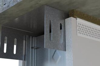
IMP panel cores, whether polyisocyanurate, mineral wool or EPS, deliver their labeled R-values through the panel field. The structural connection at panel joints, typically steel clips, zee-girts or hat channels, creates direct metal-to-metal thermal bridging that almost never gets modeled in energy compliance calculations.
This is where the single-skin assumption causes its second category of failure, separate from air leakage.
ASHRAE 90.1-2019 Appendix A, specifically the A9. 2 methodology for calculating assembly U-factors, requires that thermal bridging at framing members be accounted for in the compliance calculation.
When framing density and clip geometry are modeled using THERM 7.x, the LBNL finite element tool developed for exactly this purpose, unbroken steel girt connections reduce effective assembly R-value by 30 to 50 percent depending on framing density and climate zone. A panel with a nominal R-30 core can deliver an effective assembly R-value below R-18 once the clip pattern is modeled correctly.
In IECC Climate Zones 6 and 7, that gap can shift a project out of compliance.
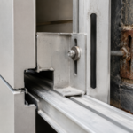
Clip and fastener geometry matters more than most specifiers realize. Proprietary IMP clip systems with integrated thermal breaks, using PTFE, polyamide or fiberglass-reinforced nylon isolators, perform measurably differently from standard steel clips.
The difference is not marginal. Specifiers should require isothermal plane calculations or 2D heat flow modeling per ISO 10211 methodology as a submittal requirement, not just labeled panel R-value.
If a manufacturer’s representative cannot produce that analysis, the thermal performance claim is incomplete by definition.
Energy models submitted with nominal panel R-value rather than assembly R-value calculated per ASHRAE 90.1-2019 Appendix A Section A9. 2 may overstate thermal performance by enough to shift climate zone compliance.
That is not a conservative interpretation. That is what the math produces when you run it correctly.
The practical consequence of this modeling gap shows up most often during energy code compliance reviews in Climate Zones 5 through 8, where prescriptive wall assembly U-factor requirements are tight enough that the difference between nominal and effective R-value determines whether the project passes without additional measures. A warehouse project in Minneapolis specified a 4-inch polyisocyanurate core IMP panel rated at R-25, submitted an energy model using R-25 as the wall assembly value and received a compliance letter.
When an enclosure consultant ran the THERM model using the actual clip pattern from the shop drawings, the effective assembly R-value came out at R-16.4. The project was out of compliance with Minnesota’s adopted energy code before a single panel was installed and nobody on the design team knew it because the specification never required the thermal bridging analysis as a submittal. Requiring that analysis costs nothing at the specification stage.
Discovering the gap during a code compliance audit after construction is complete costs considerably more and the remediation options at that point are limited to adding interior continuous insulation or accepting a performance path demonstration that the energy model cannot support.
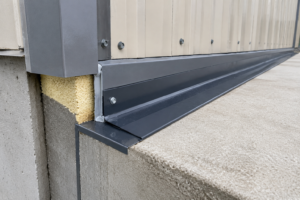
Air Barrier Continuity at Panel Joints: The Detail That Field Crews Are Left to Invent
Horizontal and vertical panel joints are the primary failure plane in IMP air barrier assemblies. The panel body may satisfy ASTM E2178 at the material level.
The joint is a designed gap and it requires an engineered continuity solution that must appear on the construction documents before the first panel goes up.
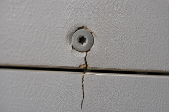
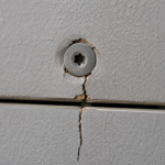
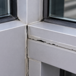
Common joint conditions each carry specific failure modes. Open-cell backer rod with sealant fails through UV degradation and adhesion failure at dissimilar substrates, particularly where the sealant must bond to a painted metal face on one side and a factory-applied coating on the other.
Compression gaskets are installation-dependent and provide no positive attachment verification; an inspector cannot look at a compressed gasket and confirm it was installed at the correct compression ratio. Fluid-applied membranes bridging the joint are the most reliable continuity solution and the least frequently specified in IMP details.
That gap between reliability and specification frequency is a professional failure.
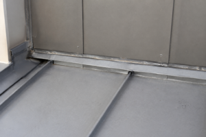
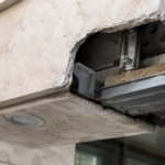
Transition conditions compound the risk. IMP-to-storefront, IMP-to-roof edge, IMP-to-foundation and IMP-to-overhead door frame each require a specific continuity detail that must be shown on the construction documents.
Delegating these conditions to the panel installer through a specification note that says “coordinate with adjacent trades” is not a detail. It is an abdication of design responsibility that creates disputed liability territory during remediation.
When contract documents show only the panel system without joint details, responsibility for air barrier continuity becomes genuinely contested between the panel subcontractor, the general contractor and the design team. Field verification per ASTM E283 and transition joint performance at storefront interfaces per AAMA 501.2 become relevant when the blower door test fails and the forensic work begins.
At that point, the absence of a detail on the construction documents is the most important document in the dispute.
The sequencing problem at transition conditions is frequently underestimated. An IMP-to-storefront transition requires that the air barrier continuity material be installed and inspected before the storefront frame is set, because the connection point between the two systems is inaccessible once the frame is in place.
If the construction documents do not show this sequence explicitly, the storefront subcontractor will set the frame on the schedule that works for the storefront subcontractor and the IMP installer will seal around it afterward with whatever material is available. That field-invented condition is what shows up as a discrete leakage point on an infrared scan conducted during blower door depressurization.
Forensic investigators working on failed IMP assemblies report that storefront corners and overhead door head conditions account for a disproportionate share of total air leakage relative to their linear footage, precisely because those conditions are where the sequencing and coordination requirements are most demanding and the construction documents are most often silent. Sealant applied over a set frame at an IMP-to-storefront condition is not an air barrier.
It is a weather seal at best and it will fail under the thermal cycling loads that the joint experiences over a service life measured in decades.
Vapor Control in IMP Assemblies: What the Panel Certifies and What the Assembly Requires
IMP systems with polyisocyanurate cores function as vapor retarders through the panel field, typically achieving Class II vapor retarder performance. That is not the same as a continuous vapor control layer across the assembly.
At joints, penetrations and transitions, the vapor control function has the same continuity problem as the air barrier function and the two problems are related. Air leakage transports orders of magnitude more moisture than vapor diffusion under equivalent driving forces.
An IMP assembly that fails its air barrier continuity test is also failing its vapor control function at every leakage site, regardless of what the panel core’s vapor permeance rating shows.
Climate zone matters here in ways that standard IMP details do not acknowledge. In IECC Climate Zones 4C, 5 and above, the vapor drive is predominantly outward in winter and the panel’s interior face functions as the primary condensing surface if warm interior air reaches the joint cavity.
In mixed-humid zones, the drive reverses seasonally. Specifying a single joint sealant condition without accounting for the vapor profile of the climate zone is a detail that will eventually produce a moisture problem even if it passes the initial blower door test.
The four control layers, water, air, vapor and thermal, must each be addressed explicitly at every joint and transition condition. IMP standard details typically address water and thermal at the panel field.
Air and vapor continuity at joints require separate engineered details and those details must be climate-zone-specific.
The moisture failure mode in IMP joint cavities is slow enough that it rarely appears during the construction warranty period, which is part of why the industry has not treated it with the same urgency as air leakage failures that show up on blower door tests. A joint cavity that allows intermittent air infiltration in a Climate Zone 6 building will accumulate moisture through repeated condensation cycles over two to five years before visible evidence appears at the interior face.
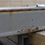
By that point, the panel clip connections and the structural substrate behind the panel may have experienced significant corrosion and the remediation scope extends well beyond resealing the joint. Cold-storage facilities are particularly susceptible because the interior temperature differential is extreme and continuous, which means the condensation potential at any air leakage site is present year-round rather than only during heating season.
The distribution facility described at the opening of this article was a cold-storage project and the $180,000 remediation figure addressed air leakage only. A moisture damage assessment was still pending at the time of that report.
Specifiers working on refrigerated warehouse, food processing or cold-storage projects should treat IMP joint vapor continuity as a structural durability issue, not just an energy code compliance issue, because the consequences of getting it wrong extend far beyond a failed commissioning test.
Specification Language That Creates the Problem and Language That Prevents It
The most common specification failure on IMP projects is a Section 07 41 13 that describes the panel product in detail and says nothing enforceable about joint continuity. Product data submittals confirm panel R-value and ASTM E2178 compliance.
Shop drawings show panel layout and clip spacing. Nobody submits a joint detail that has been reviewed against ASHRAE 90.1-2019 Section 5.
4. 3 continuity requirements because the specification never asked for one.
Preventing this requires three additions to the specification. First, require the panel installer to submit joint continuity details as part of the shop drawing package, with explicit identification of the air barrier continuity material and method at each joint type.
Second, establish an inspection hold point at joint sealing before the next panel course is installed; once the joint is covered, it cannot be verified without destructive investigation. Third, require whole-building air leakage testing per ASHRAE 90.1-2019 Section 5.
4. 3.
1 as a contract deliverable, not an optional commissioning activity.
None of these requirements adds significant cost if they are in the contract from the start. All of them become expensive when they are added after the blower door test fails.
The joint continuity submittal requirement deserves more specificity than a general instruction to show air barrier details. The specification should identify each joint type by name: horizontal panel-to-panel joints, vertical panel-to-panel joints, panel-to-foundation joints, panel-to-roof edge joints, panel-to-storefront frame joints and panel-to-door frame joints.
Each condition should require a separate detail in the shop drawing package that identifies the continuity material by product name and ASTM designation, the substrate preparation requirement, the installation sequence relative to adjacent trades and the minimum overlap or embedment dimension. Requiring this level of detail in the submittal forces the panel installer to make decisions before construction that would otherwise be made in the field by whoever is available.
It also creates a documented basis for the inspection hold point, because the inspector has a specific detail to compare against the field condition rather than a general requirement to interpret. Specifications that require joint continuity details without specifying what those details must contain will receive submittals that show a sealant bead at the joint with no substrate preparation requirement, no sequencing information and no performance basis.
That submittal will be approved because it technically responds to the specification requirement and the field condition will be no better than if the requirement had never been written. The specification language must be specific enough that a compliant submittal is also a useful construction document.
What the Next Generation of IMP Projects Needs to Get Right
The IMP industry is moving toward factory-fabricated joint gasket systems integrated into the panel edge profile, which reduces installation variability at horizontal joints. That is a meaningful improvement. It does not solve the transition detail problem