Stone Veneer Anchored Facade Systems: Kerf Anchor Selection, Thermal Movement Tolerances and Where the Structural Backup Wall Creates Hidden Risk
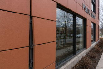
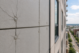
A 2019 institutional project in the Mid-Atlantic region required emergency remediation less than six years after substantial completion when kerf-anchored limestone panels on a steel-stud backup wall began exhibiting progressive cracking and two panels showed measurable outward displacement. The cause was not stone defects.
Anchor pull-out driven by backup wall deflection exceeding the kerf slot tolerance was responsible and the investigation revealed that anchor gauge, kerf depth and backup wall stud spacing had each been specified independently by different disciplines with no coordinated thermal movement analysis. This scenario is no longer an outlier.
Why Anchored Stone Veneer Is Back: and Why the Engineering Hasn’t Kept Up
Thin-panel stone technology has changed the commercial calculus on natural stone facades. Panels as thin as 3/4″ to 1-1/4″ have reduced both material cost and dead load, making anchored stone veneer competitive on mid-rise institutional and office projects where 2″ traditional ashlar was once cost-prohibitive.
Adoption is accelerating. The engineering rigor is not.
The specification problem is direct: project teams are applying details developed for thick-panel systems to thin-panel assemblies with fundamentally different structural behavior. Kerf slot geometry, anchor engagement length and edge distance requirements that were adequate for 2″ limestone become inadequate when panel thickness drops by half and the margin between the kerf and the stone face narrows accordingly.
A 2″ limestone panel with a 3/4″ kerf depth has a face shell of roughly 1-1/4″ between the slot bottom and the exposed face. That same kerf geometry on a 7/8″ panel leaves less than 1/8″ of stone between the slot root and the face, which is not a structural condition.
It is a fracture waiting to be triggered by the first significant wind event or thermal cycle. The MIA+BSI Dimension Stone Design Manual (current edition) establishes minimum panel thickness and edge distance requirements that are routinely violated in thin-panel applications, not from ignorance of the manual but from failure to cross-reference it during anchor selection.
Facade engineering firms are reporting increased anchor pull-out and panel cracking claims on projects under ten years old. That pattern is becoming a documented liability trend, not anecdote.
Part of what drives it is procurement pressure: thin-panel systems are frequently selected late in design development after the facade engineer’s scope has been reduced or eliminated, leaving anchor selection to the stone supplier’s standard details and the architect’s generic specification section. The supplier’s standard detail is optimized for the supplier’s standard conditions, not for the project’s specific backup wall stiffness, climate zone or stone lot characteristics.
The gap between product availability and engineering rigor at the specification stage is the systemic failure driving the trend.
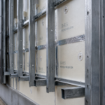
Kerf Anchor Anatomy: What Specifiers Get Wrong Before the First Drawing Is Issued
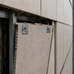
A kerf anchor system has four interdependent components: the kerf slot cut into the stone edge, the anchor body (typically stainless steel, either continuous or discrete), the setting block and the connection back to the structural substrate. Each component carries independent tolerance stacks.
Those stacks compound. Specifying them independently is how projects end up in litigation.
The most common specification error is under-sizing kerf depth relative to panel thickness. Minimum kerf depth should be 1.5 times the anchor leg engagement length; anything less reduces the bearing area at the slot walls and concentrates stress at the slot root during thermal cycling.
A kerf cut to 3/4″ depth with a 5/8″ anchor leg engagement leaves only 1/8″ of additional depth before the anchor contacts the slot bottom, which eliminates the clearance needed for differential movement and puts the full thermal load into bearing stress at the slot root. ASTM C1242, Standard Guide for Selection, Design and Installation of Dimension Stone Attachment Systems, addresses anchor engagement and edge distance minimums in Section 6 directly.
Specifiers who skip that section and default to generic details are accepting risk they haven’t calculated.
Anchor gauge selection without reference to the specific stone’s flexural strength is the second critical error. The anchor must be sized to the load, but the stone must also be capable of resisting the concentrated edge force the anchor imposes.
These are separate calculations that must be performed together. An anchor sized for a 50 psf wind zone on a 24″ x 48″ panel generates a specific edge reaction at the kerf slot that must be checked against the stone’s tested modulus of rupture with an appropriate safety factor.
Performing only the anchor load calculation and omitting the stone edge stress check is a half-calculation that produces a fully deficient design.
Stainless steel alloy selection is frequently overlooked entirely. Grade 304 is acceptable in most interior and low-exposure conditions.
Grade 316 is the minimum in coastal environments or any application with elevated chloride exposure. Projects within three to five miles of tidal water or in urban environments with road salt exposure at grade, should treat 316 as the baseline and evaluate 316L or duplex alloys for aggressive conditions.
Anchor corrosion is a slow-moving failure mode that standard visual inspections will not catch until panel displacement is already occurring. By the time rust staining appears at the joint, the anchor cross-section has frequently already lost a meaningful percentage of its load-carrying capacity.
Anchor spacing is regularly defaulted to 24″ on-center from generic details without load calculations accounting for wind uplift, panel self-weight and seismic zone requirements. ASCE 7-22 Chapter 30 governs component and cladding wind pressure requirements that drive anchor load demand.
That calculation must precede anchor selection, not follow it. On a building corner in a high-wind zone, component and cladding pressures can exceed 60 psf on panels that were specified with anchors sized for 25 psf interior field conditions.
The corner condition is not an edge case. It is a predictable geometry that appears on every rectangular building and must be calculated explicitly.
Reading the Stone Before Selecting the Anchor: Flexural Strength, Porosity and Edge Integrity
Stone is not a uniform engineering material. Flexural strength, expressed as modulus of rupture, varies significantly by species, quarry location and orientation of the bedding plane relative to the cut face.
A kerf anchor imposes a concentrated edge load. That load must be evaluated against the tested MOR of the specific quarry lot being installed, not a species-average value from a published table.
Published tables are starting points for preliminary design. They are not substitutes for certified test data.
Indiana limestone, for example, carries a published MOR range of approximately 1,800 to 2,400 psi depending on grade and grain structure. A project specifying anchors against the upper end of that range and receiving stone from a quarry lot testing at the lower end has introduced a safety factor reduction that no one calculated and no submittal review caught.
Porosity compounds the problem over time. High-absorption stones, including certain limestones and some sandstones, experience accelerated freeze-thaw degradation at the kerf slot.
Each freeze-thaw cycle enlarges micro-fractures at the slot root, progressively reducing the effective bearing area. The mechanism is straightforward: water infiltrates the kerf slot through the joint sealant, saturates the stone at the slot root and expands approximately 9% by volume upon freezing.
That expansion acts as a wedge force at the most geometrically vulnerable point in the panel. Over five to ten freeze-thaw seasons, the cumulative damage reduces the effective kerf bearing area enough to produce pull-out at loads the original anchor calculation would have carried safely.
ASTM C97, Standard Test Methods for Absorption and Bulk Specific Gravity of Dimension Stone, should be a required submittal before anchor specification is finalized. A stone with absorption exceeding 3% by weight warrants serious scrutiny in IECC Climate Zones 5 through 7.
Edge integrity testing is almost never specified, which is a failure of practice. ASTM C880, Standard Test Method for Flexural Strength of Dimension Stone, should be supplemented with kerf pull-out testing on representative samples before anchor selection is locked.
Pull-out testing on actual kerf-cut samples from the project quarry lot, using the specified anchor geometry and engagement length, produces direct empirical data on the connection capacity that no published table can replicate. The cost of that testing is modest relative to the remediation cost of a failed panel system.
The specifier’s responsibility is to require certified test data from the stone supplier for the actual quarry lot. Accepting species-average published values on a thin-panel application is accepting an unquantified structural risk.
Thermal Movement Tolerances: The Calculation Most Specifications Skip
Thermal movement in stone veneer is bidirectional and cumulative. A 30-foot run of granite in a continental U.
S. climate with a 120°F annual temperature differential generates approximately 0.10″ to 0.
14″ of linear expansion, using the thermal expansion coefficient of approximately 4.4 x 10⁻⁶ per degree Fahrenheit from the MIA+BSI Dimension Stone Design Manual. Limestone runs slightly higher at 4.4 to 5.
0 x 10-6 per degree Fahrenheit. That movement must be accommodated at joints and at the anchor connection.
It cannot be resisted without inducing stress that the stone or the anchor will eventually transfer to a failure mode.
Kerf anchor slot length must be sized to permit in-plane thermal movement without the stone bearing against the anchor body. Standard practice calls for a fixed anchor at mid-panel and slotted anchors at panel ends, allowing the panel to expand outward from its center.
This detail is frequently reversed or omitted entirely in construction documents. Reversed anchor fixity forces the panel to bear against the fixed anchor at the end condition during expansion.
The result is edge cracking at a predictable location, typically appearing within the first three to five years of service as the cumulative thermal cycles load the stone edge repeatedly against an unyielding anchor body. The crack pattern is diagnostic: a vertical crack at or near the panel end, propagating from the kerf slot toward the face, is the physical signature of a reversed fixity condition.
Differential thermal movement between the stone veneer and the backup wall creates secondary stress at the anchor connection that is almost never calculated at the specification stage. Steel studs, concrete masonry and cast-in-place concrete each have different coefficients of thermal expansion and different thermal mass.
Steel expands at approximately 6.5 x 10⁻⁶ per degree Fahrenheit. Concrete masonry runs approximately 4.5 x 10⁻⁶ per degree Fahrenheit.
Granite runs approximately 4.4 x 10⁻⁶ per degree Fahrenheit. A steel-stud backup wall and a granite veneer panel will move at different rates across the same temperature swing and the anchor is the mechanical link between two assemblies moving at different rates.
On a 20-foot floor-to-floor height with a 100°F temperature differential, the differential movement between a steel backup wall and a granite panel can exceed 0.05″, which is enough to induce measurable stress at the anchor connection if the detail does not accommodate it. That differential must be quantified and accommodated in the anchor connection detail.
Joint width calculation must account for thermal expansion, moisture expansion (particularly significant in limestone and marble) and construction tolerance simultaneously. ASTM C1472, Standard Guide for Calculating Movement and Other Effects When Establishing Sealant Joint Width, provides the methodology.
Marble carries a moisture expansion coefficient that can add meaningfully to its thermal movement and the combination of thermal and moisture expansion in a marble panel system has produced joint closure failures on projects where the 3/8″ joint was sized for thermal movement alone. The common 3/8″ joint is frequently undersized for thin-panel systems in high-temperature-swing climates.
Undersized joints transfer movement into the anchor rather than the sealant. That is a failure path, not a design solution.
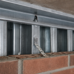
The Backup Wall as a Hidden Variable: Stiffness, Deflection and Out-of-Plane Risk
The structural backup wall is the most underspecified component in anchored stone veneer systems. Steel-stud backup walls are economical and fast to erect.
They are also flexible in ways that stone panels are not. The kerf anchor connects a relatively brittle cladding material to a backup assembly that deflects under both lateral wind load and gravity load and the deflection limits appropriate for a gypsum-sheathed interior partition are not appropriate for an anchored stone facade.
The governing deflection limit for backup walls supporting anchored stone veneer is L/600 or 3/4″ maximum, whichever is less, based on MIA+BSI guidance and standard facade engineering practice. Many steel-stud backup walls are designed to L/360, which is the IBC default for non-structural partitions.
That discrepancy is where the Mid-Atlantic failure described at the opening originated. The studs deflected within their design limit.
The kerf anchor could not accommodate the resulting displacement. The panels cracked and displaced.
The structural engineer of record was not negligent by the standard applicable to the backup wall. The facade system failed because no one had assigned responsibility for coordinating the two deflection standards and the structural drawings were issued before the facade engineer had established the cladding’s deflection demand.
That sequencing failure is common on projects where the facade engineer is brought in after the structural system is already designed.
Stud spacing, stud gauge and connection to the primary structure all affect backup wall stiffness and must be coordinated with the facade engineer before the structural drawings are issued. This coordination rarely happens on schedule.
The result is backup wall details that are structurally adequate for the building frame but mechanically incompatible with the cladding system attached to them. A 3-5/8″ 20-gauge stud at 16″ on-center spanning 12 feet will deflect significantly more under a 30 psf wind load than the kerf anchor detail can accommodate and upsizing to 6″ 16-gauge at 12″ on-center to meet L/600 changes the framing cost in ways that affect the project budget.
That conversation needs to happen in design development, not during submittal review.
Out-of-plane displacement at the anchor connection is the failure mode that produces visible panel movement. In-plane racking from seismic drift or story drift under wind creates a different but equally serious failure path, particularly at floor-line shelf angles where the anchor connection must transfer load across a horizontal joint in the backup wall assembly.
Shelf angle deflection under stone self-weight, combined with anchor eccentricity at the kerf slot, produces a moment condition at the anchor body that discrete anchor designs handle very differently than continuous angle systems. A discrete two-point anchor at a shelf angle location concentrates the eccentric moment load at two small bearing areas.
A continuous angle system distributes that load along the full panel width. The choice between discrete and continuous anchor geometry at shelf angle conditions is a structural decision that belongs in the facade engineer’s calculations, not in a supplier’s standard detail sheet.
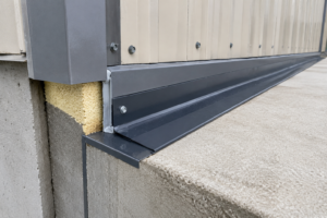
Water Control at the Anchor Plane: Where the Four Control Layers Get Compromised
Anchored stone veneer is a drained cladding assembly. The cavity between the stone and the backup wall is the primary drainage plane and the water control layer on the face of the backup wall is the last line of defense against bulk water reaching the structure.
Every anchor penetration through that water control layer is a potential failure point. On a typical mid-rise facade with discrete anchors at 24″ on-center horizontally and 18″ on-center vertically, a single floor plate can carry several hundred individual anchor penetrations through the water-resistive barrier.
Each one is an opportunity for water infiltration if the detailing is not executed correctly and consistently.
Most anchor systems penetrate the air and water barrier at the backup wall face. Each penetration requires a detail that maintains continuity of the water control layer around the anchor body.
In practice, this means back-sealing anchor plates to the WRB substrate before the stone is set, using a compatible sealant that will remain flexible through the thermal cycling the anchor connection will experience. The sealant selection must be compatible with both the WRB membrane and the anchor material.
Incompatibility between sealant and membrane chemistry produces adhesion failure within two to three years, long before any visual inspection would identify the breach. Fluid-applied WRB membranes and silicone sealants are generally compatible, but sheet-applied self-adhered membranes and certain polyurethane sealants have documented incompatibility issues that have produced adhesion failures on projects where the specifier selected each product independently from different sections of the specification without cross-referencing chemical compatibility.
The WRB manufacturer’s written approval of the sealant product should be a required submittal, not an assumption.
The air control layer is equally at risk. Air leakage at anchor penetrations drives moisture-laden air into the cavity and toward the backup wall assembly, creating condensation risk that depends on climate zone and vapor drive direction.
In IECC Climate Zones 5 through 7, inward vapor drive in winter pushes moisture toward the backup wall; a compromised air barrier at the anchor plane accelerates that process. Cavity insulation installed between the stone and the backup wall complicates the condensation analysis further, because the dew point location shifts depending on insulation thickness and thermal resistance.
Projects in Climate Zone 6 with 2″ of mineral wool in the cavity and a compromised air barrier at the anchor plane have produced condensation on the interior face of the WRB that was not detected until interior finishes showed moisture staining two to three years after occupancy. Treating anchor penetrations as incidental details rather than air barrier continuity points is a specification failure with consequences that appear years after occupancy.
What the Specification Must Require That It Usually Doesn’t
The specification gap in anchored stone veneer work is not a knowledge problem. The standards exist. ASTM C1242, ASTM C880, ASTM C97,