
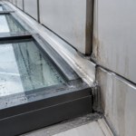
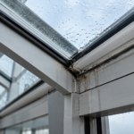
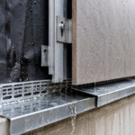
- Terra cotta copings meeting ASTM C1405-21 Grade SW are still failing because of mortar, flashing and joint spacing errors.
- Generic coping provisions in TMS 402/602-22 were calibrated for CMU and precast and do not address terra cotta’s thermal behavior.
- Type S mortar in a full bed creates restraint stress that exceeds terra cotta’s tensile strength and guarantees cracking over time.
- Movement joints at 20-foot spacing copied from brick veneer practice are too far apart for exposed parapet coping units in cold climates.
- Specifiers must explicitly address mortar type, bed thickness, flashing termination geometry and joint spacing because the standard does not.
Terra Cotta Copings: Freeze-Thaw Failures Start at the Detail
A civic library completed in 2019 in Minneapolis specified period-appropriate fired terra cotta copings to match the building’s 1930s original wing. Within 18 months of substantial completion, face spalling and mortar joint cracking appeared across the parapet top.
Laboratory analysis confirmed the units met ASTM C1405-21 Grade SW requirements. The terra cotta was not the problem.
The mortar bed thickness ignored differential thermal movement, cap flashing terminations directed water into the bed joint rather than away from it and movement joints were spaced at 20 feet on a parapet geometry that demanded 10. Three correctable specification errors. One expensive remediation.
That project is not an outlier. It is the pattern.
Why Terra Cotta Copings Are Back and Why the Detailing Hasn’t Kept Up
Preservation mandates and aesthetic continuity requirements on institutional and civic projects are driving renewed specification of traditional fired terra cotta copings. State historic preservation offices increasingly require material compatibility rather than material substitution on additions to contributing structures and multiple domestic and European manufacturers now supply custom-profile units that make the specification practical.
Boston Valley Terra Cotta, Gladding McBean and several German suppliers have expanded their coping profile libraries substantially in the past decade and lead times that once made custom terra cotta impractical on tight schedules have compressed enough that specifiers can realistically include it in competitive bid documents.
The detailing guidance has not followed.
TMS 402/602-22 provides general coping requirements under Section 6.3, addressing minimum overhang, drip edge geometry and slope. It contains no terra cotta-specific provisions for mortar bed design, flashing integration or joint spacing at parapet tops.
The standard treats copings as a generic category. That assumption works reasonably well for CMU caps and precast units.
It fails for fired terra cotta because the material’s thermal and mechanical properties sit outside the range those generic provisions were calibrated for. CMU caps are typically cast monolithically with the wall below or set in a full mortar bed with control joints that match the wall system.
Precast concrete copings carry higher tensile capacity and tolerate the restraint a full mortar bed develops. Neither condition applies to terra cotta.
Specifiers filling that gap are defaulting to brick coping details. That is the wrong baseline.
Brick copings are set in continuous mortar beds, tolerate higher restraint stress and benefit from decades of published BIA guidance, including Technical Note 36 on brick masonry copings. Terra cotta copings are thinner-walled, lower in tensile capacity and more sensitive to the restraint conditions a full mortar bed creates.
The wall thickness on a typical terra cotta coping unit runs 3/4 to 1 inch on the face shell. A solid brick unit presents a fundamentally different cross-section to the same restraint force.
Applying brick coping assumptions to terra cotta units produces the Minneapolis result.
How Fired Terra Cotta Actually Behaves Under Freeze-Thaw Cycling
The thermal expansion coefficient of fired terra cotta runs approximately 3.0 to 4. 5 times 10 to the negative sixth power per degree Fahrenheit.
Portland cement mortar sits at approximately 5.5 to 6. 0 times 10 to the negative sixth power per degree Fahrenheit.
That differential is not trivial across a 100-degree daily temperature swing, which parapet tops in IECC Climate Zone 6 and colder routinely experience. The parapet top is the most thermally exposed element on the building envelope: unshaded, subject to direct solar gain on the top surface and cold air exposure on both vertical faces simultaneously.
The unit and its mortar bed are not moving together. They are fighting each other.
Terra cotta’s tensile strength typically runs under 500 psi. That number matters because it defines the failure threshold when restraint prevents free thermal movement.
The unit cannot stretch. It cracks instead.
On a parapet in Minneapolis, Chicago or Buffalo, the temperature differential between a sun-exposed coping surface in July and the same surface on a clear January night can exceed 150 degrees Fahrenheit. Across a 10-foot run of coping, that temperature swing produces measurable dimensional change.
When the mortar bed prevents that change from occurring freely, the stress accumulates in the unit’s face shell, which is the thinnest and most exposed section of the profile.
ASTM C67-23 provides the standard freeze-thaw cycling test protocol for brick and structural clay tile. Units that pass laboratory cycling under ASTM C67-23 conditions can still fail in service and this is the part that confuses specifiers.
The laboratory test cycles the unit without restraint. It does not replicate the boundary conditions of a full mortar bed on a parapet top where the unit is bonded to a substrate with a different coefficient of thermal expansion, loaded with water from a failed flashing detail and subjected to temperature gradients the test chamber does not produce.
The ASTM C67-23 protocol saturates the unit and cycles it through 50 freeze-thaw events. It measures weight loss and dimensional change.
It does not measure stress accumulation at a bonded interface under differential thermal movement. Passing ASTM C67-23 confirms material quality.
It says nothing about installation survivability under restraint.
ASTM C1405-21 Grade SW absorption limits define the minimum standard for severe weathering zones. The maximum cold water absorption for Grade SW is 11 percent by weight and the saturation coefficient maximum is 0.78.
Specify Grade SW without exception for any terra cotta coping in IECC Climate Zones 5 through 8. That is the floor, not the target. Some manufacturers can supply units with absorption values well below the Grade SW maximum and for parapet coping applications in Zone 6 and colder, requesting certified test data and selecting units in the lower half of the allowable absorption range is a reasonable additional requirement.
The Mortar Bed Problem: Thickness, Mix and Restraint
Setting terra cotta copings in a full mortar bed at 3/4 to 1 inch thickness creates a continuous, rigid restraint plane. The unit cannot respond independently to thermal movement.
Every degree of temperature change accumulates stress at the unit-to-mortar interface until something gives. Given the tensile strength differential between Type S mortar and the terra cotta unit, what gives is the unit.
Type S mortar has a minimum compressive strength of 1,800 psi per ASTM C270-19a. The terra cotta unit fails in tension well below that threshold.
Specifying Type S mortar for terra cotta coping installation is specifying the wrong material for the boundary condition. The mortar wins.
The unit cracks. This is not a probabilistic outcome; it is a mechanical certainty given sufficient thermal cycling.
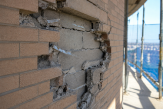
The failure mode is consistent across projects: horizontal cracking at the bed joint face, followed by face shell delamination, followed by spalling that exposes the hollow core of the unit to direct water infiltration. Once the core is exposed, freeze-thaw cycling accelerates and the unit deteriorates rapidly regardless of its original Grade SW compliance.
The correct mortar specification is Type N per ASTM C270-19a, with a minimum compressive strength of 750 psi or a proprietary polymer-modified mortar with a demonstrably lower modulus of elasticity. Combine that with a controlled bed thickness of 1/2 inch maximum.
Reducing bed thickness reduces the bonded surface area and therefore reduces the restraint force the bed can develop against a moving unit. Both variables matter.
Specifying Type N mortar at 1-inch bed thickness still produces excessive restraint. Specifying Type S mortar at 1/2-inch bed thickness still produces a mortar that can fracture the unit.
Address both simultaneously. Some specifiers have had success with pre-blended masonry mortars formulated specifically for thin-bed terra cotta setting, which carry published modulus of elasticity values that allow direct comparison against the unit’s tensile capacity.
When that data is available from the manufacturer, use it to verify compatibility rather than relying on mortar type designation alone.
The mortar bed slope is the third variable that gets omitted. A minimum 1:12 slope toward the exterior face is standard practice for any coping assembly.
In terra cotta coping installation, it is routinely missing from shop drawings and absent from field installation. Masons accustomed to setting brick copings on a flat bed do not automatically introduce slope unless the specification and the reviewed shop drawings require it explicitly.
Water ponds at the unit-to-substrate interface, saturates the bed joint and is present in liquid form when the first freeze event arrives. That is the condition that produces spalling at the most vulnerable location in the assembly.
The slope requirement belongs in the specification, in the shop drawing review comments and in the preconstruction meeting agenda.
Cap Flashing Integration: Where Water Gets In and Stays
Terra cotta coping units with internal drip profiles require cap flashing that terminates into the unit’s back leg reglet or under the unit’s rear overhang. This is not the default detail for metal or precast copings and specifiers who copy those details onto terra cotta assemblies create a predictable failure mode.
The geometry of a terra cotta coping profile is not interchangeable with a sheet metal coping cap and the flashing termination logic that works for one does not transfer to the other without deliberate modification.
The common failure: cap flashing terminated at the face of the parapet wall below the coping unit, leaving the mortar bed joint between flashing and unit as the primary water exclusion line. That joint opens under thermal cycling.
It opens every winter. Water enters, migrates into the mortar bed and has no exit path if the through-wall flashing layer is also absent.
Field observation on remediation projects consistently shows the same pattern: the flashing was installed correctly relative to the metal coping detail it was copied from and incorrectly relative to the terra cotta unit geometry it was actually serving. The detail was not wrong in isolation.
It was wrong for the assembly.
Through-wall flashing at the parapet top course, below the coping unit, must be continuous and slope to scuppers or weep locations. Omitting this layer means any water that penetrates the bed joint saturates the substrate before freeze events occur.
The substrate holds that water. The terra cotta unit above it freezes from below.
Face spalling follows. The through-wall flashing material must be compatible with the mortar bed chemistry.
Copper flashing in contact with Portland cement mortar can experience accelerated corrosion at the mortar interface over time. Self-adhered membrane flashing or stainless steel are more chemically compatible choices for the through-wall layer in this assembly.
The sealant detail at the flashing-to-unit interface requires a bond-breaker tape and a low-modulus sealant classified under ASTM C920-22 as Type S, Grade NS, Class 25 minimum. High-modulus sealants applied without bond-breaker create a rigid connection between the flashing and the coping unit’s rear edge.
When the unit moves thermally and the sealant does not accommodate that movement, the force transfers directly into the face of the unit. A Class 25 sealant accommodates plus or minus 25 percent joint movement.
At a 3/8-inch joint width, that means the sealant can accommodate approximately 3/16-inch of total movement before it reaches its performance limit. Verify that the anticipated thermal movement at the joint location falls within that range before finalizing the joint width and sealant classification.
The SMACNA Architectural Sheet Metal Manual, 8th Edition, provides applicable cap flashing termination details as a reference baseline, though those details require modification for terra cotta unit geometry. Use them as a starting point, not a final answer.
Movement Joints: The Most Consistently Underspecified Variable
The industry default of 20 to 25-foot movement joint spacing derives from brick veneer practice. It is the wrong number for terra cotta coping units and applying it is one of the most consistent errors in current specifications.
The number appears in project documents because it appears in the previous project’s documents and the previous project’s documents copied it from brick veneer guidance without examining whether the underlying conditions that produced it apply to a parapet coping assembly.
Brick veneer assemblies have a cavity that absorbs some differential movement. They are backed by a continuous substrate with its own stiffness.
The coping unit at a parapet top has none of those conditions. It sits on a mortar bed, exposed on three sides, subject to higher thermal amplitude than any other element in the assembly and restrained by a bed that prevents independent movement.
The thermal load is higher. The relief mechanism is absent.
The joint spacing must be tighter. A brick veneer panel at 20-foot joint spacing is also a much larger mass of material with a higher aggregate thermal inertia than a single-wythe row of coping units.
The coping units respond to temperature changes faster and with greater amplitude because they have less thermal mass to buffer the swing.
For terra cotta copings in IECC Climate Zones 5 and colder, maximum movement joint spacing is 10 feet. This is a best practice recommendation, not a code requirement.
TMS 402/602-22 does not specify this interval for terra cotta. It should.
Until it does, the specifier carries the obligation to establish it explicitly in the project documents. Parapet geometry often creates natural joint locations at corners, pilasters and expansion joint conditions in the wall below.
Map those locations first, then fill in intermediate joints at 10-foot maximum spacing. Where the geometry produces a run longer than 10 feet between natural break points, the intermediate joint location must appear on the contract drawings, not be left to field determination.
Joint width matters as much as spacing. A joint at 10-foot centers that is only 1/4 inch wide closes under thermal expansion before it can function as a relief point.
Minimum joint width for terra cotta coping movement joints in Zone 5 and colder is 3/8 inch, filled with a backer rod and the same ASTM C920-22 Type S, Grade NS, Class 25 sealant specified at the flashing interface. The backer rod diameter should be 25 percent larger than the joint width to ensure adequate compression and a proper two-point adhesion condition for the sealant.
Coordinate the joint locations with the flashing system. A movement joint that bisects a continuous flashing run without a corresponding flashing break detail creates a new water entry point while solving the movement problem.
The flashing must be detailed to accommodate movement at the same location the coping joint is designed to move.
What the Specification Has to Say That the Standard Does Not
The absence of terra cotta-specific coping provisions in TMS 402/602-22 places the entire burden of performance on the project specification. That is not a comfortable position, but it is the current reality.
The specifier cannot rely on the standard to carry the technical requirements that protect the assembly. When a failure occurs and the contractor points to TMS 402/602-22 Section 6.3 as the basis for the installed detail, the specifier who did not go beyond that standard in the project documents has limited recourse.
The standard does not prohibit the conditions that cause failure. It simply does not address them.
Section 04720 of the project specification or the equivalent section under MasterFormat for architectural terra cotta, must explicitly address mortar type and maximum bed thickness, cap flashing termination geometry relative to the unit profile, through-wall flashing continuity and drainage path, movement joint spacing and minimum width and sealant classification by ASTM C920-22 type, grade and class. None of these items appear in TMS 402/602-22 Section 6.3 at the level of specificity the assembly requires.
If the specification does not establish them, the contractor will default to the brick coping detail on the last project. That default produces the Minneapolis outcome.
The specification section should also identify the specific terra cotta unit profile by manufacturer reference or approved equal, because the flashing termination geometry is profile-dependent and a generic specification that allows any compliant unit creates a condition where the approved submittal may not match the flashing detail in the contract drawings.
Submittals must include the mortar mix design, not just the mortar type designation. Type N mortar mixed with excessive Portland content can exceed the compressive strength of Type S mortar from a compliant mix.
The designation alone is insufficient quality control. Require a certified mix design and a preconstruction mockup panel that replicates the full assembly including flashing integration and movement joint execution.
The mockup should be constructed by the crew that will perform the work, not a demonstration crew and it should remain in place long enough to be reviewed during a scheduled site observation. Review it in the field before the first unit goes on the building.
Special inspection requirements for mortar bed thickness and slope should be included in the special inspections program, with inspection frequency tied to the linear footage of coping rather than a single pre-installation observation.
The Longer-Term Risk Nobody Is Accounting For
Climate Zone boundaries are not static. IECC Climate Zone mapping has shifted across multiple code cycles and the thermal amplitude at parapet tops in transitional zones is already producing failure patterns that were historically associated with Zone 6 and colder climates.
Zone 4 projects in the mid-Atlantic and upper South are now presenting with spalling patterns that practitioners previously associated with northern climates, driven by increased temperature swing frequency rather than lower absolute minimums. Specifiers working in Zone 5 today should detail as if the project sits in Zone 6. The cost difference between 10-foot and 20-foot movement joint spacing is negligible in the context of a masonry parapet assembly.
The cost of remediating spalled terra cotta copings on a civic building five years after occupancy is not.
Terra cotta is a legitimate, durable material for parapet coping applications in cold climates. The Minneapolis library failure was not a material failure.
It was a specification failure, compounded by a field execution failure, enabled by a standard that does not yet address the material’s specific installation requirements. The material can perform.
The detailing has to be built for what the parapet top actually experiences, not for what a generic coping provision assumes.