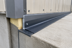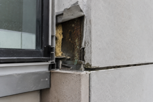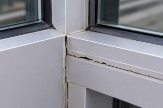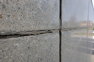
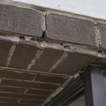
- Uncoordinated electrical conduit penetrations through curtainwall pressure plates are the leading cause of thermal break failures in EC glazing installations.
- Wire routing through aluminum framing without engineered penetration details creates cumulative thermal bridges that no post-installation remediation can fully correct.
- EC IGU edge materials introduce sealant compatibility variables that standard ASTM C920 and C1184 testing protocols were not designed to evaluate.
- Thermal modeling must include the dark tint state as a boundary condition to accurately predict condensation risk at framing sightlines during heating season.
- Explicit specification language assigning coordination responsibility across trades is the only reliable mechanism to prevent scope-gap failures on EC glazing projects.
A newly completed Class A office tower in the Pacific Northwest reported widespread interior condensation along the sill framing of its electrochromic curtainwall system within the first heating season. The failure traced not to the IGU itself but to uncoordinated electrical conduit penetrations through the pressure plate that compromised thermal break continuity.
The glazing contractor, curtainwall fabricator and EC glazing manufacturer each pointed to the others’ scope as the source. The result was a multi-party warranty dispute that delayed occupancy sign-off by four months.
This is not an isolated incident. It is becoming a predictable outcome when electrochromic glazing is specified without envelope-level electrical and thermal coordination from the earliest stages of facade design.
What Electrochromic Glazing Actually Demands from a Curtainwall System
Electrochromic glazing operates through a low-voltage DC current applied across bus bars embedded at the IGU edges, triggering an electrochemical reaction in a thin-film coating that shifts visible light transmittance across a defined range. The electrical supply must reach each unit continuously, which means lead wires must route through or around the curtainwall framing.
That routing path is not incidental. It is a building systems coordination problem embedded inside a facade fabrication problem.
EC IGUs are physically larger than standard units. Typical EC assemblies run 1.5 to 1.
75 inches total thickness compared to a standard 1-inch insulating glass unit. That difference has direct consequences for glazing pocket depth and minimum bite dimensions.
IGMA TM-3000 sets baseline benchmarks for glazing bite and pocket geometry; EC units push against those limits before any electrical accommodation is factored in. A curtainwall system sized for a standard 1-inch IGU may require extrusion substitution or custom pocket extensions to accept an EC unit and that substitution has its own thermal performance implications that must be remodeled.
Voltage requirements typically range from 0 to 5V DC with current draws up to 2 amps per unit. Cumulative load across a full facade elevation requires a coordinated electrical riser strategy that involves the MEP engineer, not just the glazing contractor.
On a 200,000-square-foot tower with EC glazing on all four elevations, the aggregated current demand across hundreds of individually addressed zones requires dedicated low-voltage panels, home-run wiring strategies and zone controllers that must be physically located somewhere in the building core or interstitial ceiling space. That infrastructure does not appear in a standard curtainwall specification and is rarely shown on early-stage electrical drawings.
EC glazing is a building system. Treating it as a product substitution for a standard IGU is the single most common error this industry makes and it consistently produces coordination failures that no amount of post-installation remediation can fully correct.
The Electrical Penetration Problem: Where Envelope Integrity Breaks Down
The bus bar lead wires must exit the IGU edge and connect to a power distribution network. In a standard curtainwall system, the pressure plate, cap and glazing pocket are designed to manage water, air and thermal control.
None of those components include provisions for low-voltage wire penetrations. The result is that each project generates a field-improvised solution and field-improvised solutions applied to the building envelope’s primary control layers are how warranty disputes begin.
Common approaches include drilling through aluminum pressure plates, routing wires through silicone reglets or notching polyamide thermal struts to create a wire chase. Each of these fails at least one control layer.
Drilling through pressure plates creates a direct metal-to-metal conduction path that bypasses the polyamide thermal break entirely. That breach is not cosmetic.
It measurably degrades the framing’s condensation resistance factor as defined under NFRC 100, which governs U-factor procedures for fenestration products and accounts for thermal bridge contributions at framing members. A single uninsulated fastener penetrating a thermal break can reduce the local condensation resistance factor by 15 to 20 percent depending on framing geometry and climate zone.
A wire penetration at the same location, repeated at every IGU across an elevation, produces a cumulative thermal bridge load that the original energy model never accounted for.
Notching thermal struts is worse. The polyamide strut is the primary thermal break in most thermally improved curtainwall systems.
Compromising its cross-section to pass a wire bundle reduces its effective thermal resistance and introduces a stress concentration that can propagate under cyclic thermal loading. Polyamide struts are designed to carry shear loads transferred between the interior and exterior aluminum extrusion halves.
Removing material from that cross-section to accommodate a wire bundle is structurally equivalent to notching a structural member in a location that sees repeated load reversals. The curtainwall fabricator’s structural calculations do not account for that modification and the modification is typically made in the field without engineering review.
AAMA 501.2 field water leakage testing has a specific limitation here: the standard checks for water infiltration under uniform static pressure differential, but it cannot detect air infiltration pathways created by wire penetrations that are subsequently sealed with field-applied silicone. Those seals degrade.
Silicone applied in the field over a wire bundle exiting a drilled hole in an aluminum pressure plate cannot achieve the adhesion geometry or compression seal that a designed penetration detail provides. The absence of a standardized penetration detail means no envelope engineer reviews the solution before it becomes permanent and the AAMA 501.2 test that gets performed at the mock-up wall passes because the test protocol was not designed to find this failure mode.
Thermal Stress Differentials and IGU Edge Seal Vulnerability
EC coatings absorb solar energy during switching transitions. The absorptance differential between the EC lite and the outboard lite creates non-uniform thermal expansion across the IGU assembly.
Published technical data from EC manufacturers document surface temperature differentials of 15 to 30 degrees Fahrenheit between switching states. That range matters because it is additive to the baseline solar-driven temperature gradient the edge seal already manages.
Edge seal systems rely on a primary polyisobutylene seal and a secondary seal in either silicone or polysulfide. Both are rated for defined temperature ranges and cyclic movement.
ASTM E2188, E2189 and E2190 govern IGU performance and edge seal durability testing, but those test protocols were not developed with EC thermal cycling patterns in mind. The cyclic temperature swings generated by repeated tint-state transitions over a service life of 20-plus years represent a fatigue loading condition that standard IGU qualification testing does not replicate.
A conventional IGU on a west-facing elevation in Phoenix might experience 30 to 40 significant thermal cycles per year driven by solar exposure. An EC IGU on the same elevation, switching between clear and dark tint states multiple times per day in response to a building automation command, can accumulate that same cycle count in a single month.
The edge seal chemistry and geometry were not qualified against that duty cycle and no ASTM protocol currently requires that they be.
The glazing pocket geometry in standard curtainwall extrusions compounds the problem. Setting block placement and pocket clearances are calculated for the thermal movement of a passive IGU.
EC operation generates additional perimeter movement that those calculations do not capture. Manufacturer-published operating temperature limits for EC IGUs typically cite a surface temperature ceiling around 185 degrees Fahrenheit.
South and west orientations in IECC Climate Zone 3 and 4 can approach that limit in dark tint states during peak solar exposure. A dark-tinted EC unit on a west elevation in Sacramento or Atlanta during a July afternoon is operating near the boundary of its published thermal tolerance and the glazing pocket geometry around it was sized for a unit that never approaches that temperature.
Recalculating setting block positions and verifying pocket clearances against EC-specific movement data is not optional on those orientations. It is the minimum due diligence required before releasing shop drawings.
Perimeter Sealant and Gasket Compatibility: An Underspecified Interface
Standard EC IGU edge construction includes conductive bus bar tapes, polymer encapsulants and edge-deletion zones where the EC coating is removed to prevent electrical shorting. These materials are not present in conventional IGUs.
Structural silicone qualified under ASTM C1184 and weatherseal sealants qualified under ASTM C920 are tested against conventional glass substrates, aluminum spacers and standard edge materials. Compatibility testing against EC-specific edge components is not universally performed or documented.
This is a specification gap with real consequences. Sealant adhesion failure at an EC edge-deletion zone looks identical to a standard sealant bond failure during a post-occupancy investigation.
Attributing it to the correct cause requires knowing what materials were present at the interface, which requires documentation that most project files do not contain. The edge-deletion zone on an EC IGU exposes a substrate that includes residual coating materials, conductive adhesive tapes and polymer encapsulant films.
Each of those materials presents a different surface energy and adhesion profile than the aluminum or glass substrates that sealant manufacturers use for standard qualification testing. A sealant that passes ASTM C920 Type S Grade NS Class 25 testing against aluminum and glass may exhibit adhesion loss within two to three years when applied against an EC edge-deletion zone and no standard test protocol will have predicted that outcome.
ASTM C1401, the standard guide for structural sealant glazing, provides a framework for compatibility testing that can be extended to EC edge materials. The requirement should be explicit in the specification: written compatibility documentation from both the sealant manufacturer and the EC glazing manufacturer, submitted and approved before fabrication release.
Not after. Not as a submittal condition that gets waived under schedule pressure.
The compatibility testing itself requires lead time, typically six to eight weeks for a full adhesion and cohesion test series and that timeline must be built into the project schedule at design development, not discovered during submittal review.
Gasket compression loads add another variable. Standard curtainwall pressure plate systems assume uniform IGU edge stiffness.
Bus bar hardware embedded at EC IGU edges creates localized stiffness variations. Those variations alter gasket seating and compression uniformity in ways that are not visible during installation and not detectable until air infiltration or water intrusion appears at the perimeter.
A gasket that seats uniformly against a standard IGU edge will bridge across the bus bar hardware location on an EC unit, leaving a gap in compression that creates a direct air pathway from the glazing pocket to the interior. The AAMA 800 series sealant standards address curtainwall sealant applications broadly but do not address this specific condition and no published gasket selection guide currently accounts for bus bar hardware as a variable in compression load calculations.
Condensation Risk at the Framing Interface: Reading the Failure Pattern
Condensation on interior framing surfaces is the visible symptom of compounded failures. Degraded thermal break continuity from wire penetrations, altered interior surface temperatures from EC tint-state cycling and increased air infiltration at compromised perimeter seals all contribute simultaneously.
The failure pattern at the Pacific Northwest tower described in the opening was not caused by a single defect. It was caused by three independent integration failures that each fell below the threshold of individual concern but combined to push the sill framing below its dew point temperature during heating season operation.
EC glazing in dark tint states reduces solar heat gain to the interior, which is the intended performance outcome. The thermal consequence is that interior glass surface temperatures drop below what was modeled at specification.
In IECC Climate Zone 5 and colder, that reduction can lower the effective condensation resistance of the overall assembly below the threshold required to prevent condensation at framing sightlines. THERM or equivalent 2D thermal modeling needs to include the dark tint state as a boundary condition, not just the clear state that typically drives the U-factor calculation submitted for energy code compliance under ASHRAE 90.1-2022.
A project that models the clear-state U-factor and condensation resistance for code compliance, then specifies EC glazing that will operate in dark tint for 40 to 60 percent of occupied hours, has submitted a thermal compliance package that does not represent the building’s actual operating condition. That gap between the modeled state and the operating state is where the condensation failures occur.
The wire penetration failure mode is the most preventable. It requires a coordinated penetration detail developed during design development, not resolved in the field.
When that detail is developed early, it can be incorporated into the curtainwall fabricator’s extrusion design, reviewed by the envelope engineer for thermal break continuity and coordinated with the EC manufacturer’s lead wire routing requirements before a single piece of aluminum is extruded. When it is resolved in the field, none of those reviews occur and the building owner inherits a thermal bridge at every IGU location that no warranty will cover because no single party is responsible for the gap between scopes.
Coordination Failures and the Scope Gap Between Trades
The warranty dispute pattern in EC glazing failures follows a consistent structure. The EC glazing manufacturer’s warranty covers the IGU and the switching system.
The curtainwall fabricator’s warranty covers the framing system as fabricated. The glazing contractor’s warranty covers installation workmanship.
Wire penetration details, sealant compatibility at EC edges and thermal break modifications fall into the gaps between all three scopes simultaneously.
No single party owns the interface. The envelope engineer of record, if one is engaged, typically reviews submittals rather than developing the penetration details.
The MEP engineer designs the low-voltage distribution system to the curtainwall zone but does not detail the last few inches through the framing. The result is that the most consequential detail on the project gets resolved by a glazing contractor’s foreman and an EC manufacturer’s field representative standing at the mock-up wall the week before glazing begins.
That resolution happens under schedule pressure, without thermal modeling, without structural review of any thermal strut modifications and without a record document that anyone will be able to locate when the condensation appears eighteen months later.
The mock-up wall sequence makes this failure mode particularly difficult to catch. AAMA 501.1 and ASTM E1105 mock-up testing protocols evaluate the curtainwall system under controlled laboratory or field conditions, but they test the system as installed at the time of the test.
The wire penetration seals are fresh, the silicone has not yet experienced a heating season’s worth of thermal cycling and the test duration is too short to detect the slow air infiltration that develops as field-applied sealant loses adhesion at an EC edge-deletion zone. The mock-up passes.
The project proceeds. The failures appear in year one or two of occupancy, after the construction team has demobilized and the warranty clock has started running.
This is a project delivery problem as much as a technical one. The specification must assign explicit coordination responsibility.
Section 08 80 00 of the project manual should require the EC glazing manufacturer to submit a coordinated penetration detail reviewed and approved by the envelope engineer before the shop drawing package is released. That requirement needs to be mirrored in the electrical and curtainwall specification sections.
Without that mirroring, the requirement in one section becomes a submittal that the other trades are not contractually obligated to participate in and the coordination meeting becomes a single-trade exercise that cannot resolve a multi-trade interface problem.
What Coordinated Specification Actually Requires
The gap between what EC glazing manufacturers publish in their installation guides and what a curtainwall system actually needs is wide enough to drive a warranty dispute through. Closing it requires specification language that is more prescriptive than most architects are accustomed to writing for glazing systems.
At minimum, the project specification should require: a manufacturer-provided penetration detail for each curtainwall framing condition present on the project; written sealant compatibility documentation per the ASTM C1401 framework for all EC-specific edge materials; THERM modeling of the framing assembly in both clear and dark tint states submitted as part of the thermal compliance package; and a pre-installation coordination meeting that includes the curtainwall fabricator, glazing contractor, EC manufacturer’s technical representative and the envelope engineer of record.
The penetration detail requirement deserves additional specificity in the specification language. The detail should identify the wire routing path from the IGU edge to the low-voltage distribution point, the method of maintaining thermal break continuity at any framing penetration, the sealant or gasketing used to maintain air and water control at the penetration and the party responsible for installing each component.
Generic language requiring the contractor to “coordinate with the EC manufacturer” does not produce a reviewed detail. It produces a phone call between a foreman and a manufacturer’s technical hotline, followed by a field improvisation that no engineer ever sees.
The THERM modeling requirement should specify that the dark tint state model use the EC manufacturer’s published absorptance values for the EC lite at maximum tint as the boundary condition for interior surface temperature calculation. That calculation should be compared against the interior design conditions, including relative humidity, for the project’s climate zone to verify that the framing sightline temperatures remain above dew point during heating season operation.
If they do not, the specification should require a corrective measure, whether that is a change in framing system, a supplemental interior perimeter heating strategy or a restriction on dark tint operation during extreme cold weather events, before the project proceeds to construction documents.
The coordination meeting requirement sounds procedural. It is not.
It is the only mechanism that forces the penetration detail to be reviewed by someone who understands all four control layers before a single unit is installed. Electrochromic glazing will continue to be specified at increasing rates on energy-code-driven commercial projects.
The envelope failures will continue at the same rate until the specification catches up to the system’s actual integration requirements.