
EIFS Over CMU: Where the Assembly Fails, Why It Gets Specified Anyway and What the Drainage Mat Detail Actually Has to Do
A forensic investigation on a 2009-vintage mid-rise medical office building tells a story that repeats itself across North America with depressing regularity. Saturated CMU cores.
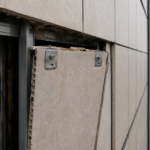
Corroded embedded lintels. Delaminated EIFS panels behind a façade that passed its original inspection.
The drainage mat specified on the drawings was never installed. The base coat was applied directly to unprepared CMU face shells.
The through-wall flashing at the shelf angle terminates two inches short of the weep screed, creating a moisture trap that has been collecting water for fifteen years. This building is not an outlier.
It is a pattern and the forensic investigation pipeline on mid-2000s to mid-2010s commercial construction is making that pattern impossible to ignore.
Why EIFS Over CMU Keeps Getting Specified Despite the Risk
Budget math drives this specification more than any other single factor. EIFS installed over CMU consistently undercuts brick veneer by $8 to $14 per square foot installed and beats metal panel systems on both first cost and thermal continuity without the detailing complexity of a rainscreen cavity.
On budget-constrained institutional and commercial projects, that differential is the conversation. Design flexibility and fast installation close the argument.
EIMA market data places EIFS among the top three specified exterior cladding systems for mid-rise commercial construction in North America, a position it has held for two decades despite a well-documented litigation history that should give any specifier pause. The system works when it is detailed and installed correctly.
The problem is that specifiers frequently inherit it from a previous project phase or owner preference without independently evaluating the substrate-specific risks that make CMU a fundamentally different application than EIFS over gypsum sheathing or concrete.
The thermal performance argument is legitimate. In IECC Climate Zones 4 through 7, EIFS with 3 to 4 inches of EPS or mineral wool provides continuous insulation (CI) that genuinely improves effective R-value across the assembly while minimizing the linear thermal bridging at shelf angles that plagues brick veneer shelf angle details.
That is a real benefit. It does not make the moisture control problem disappear.
What makes the specification pattern particularly persistent is that the failures are slow. A building that was improperly detailed in 2008 may not show visible exterior distress until 2018 or 2022, long after the design team has moved on and the original specification decisions are difficult to reconstruct.
The feedback loop between specification error and visible consequence is long enough that the same errors recycle through the next generation of projects without correction. Owners who experience failures frequently attribute them to contractor workmanship rather than specification gaps, which means the design community does not always receive the signal that its details are generating claims.
That attribution problem is worth naming directly, because it shapes how the industry responds to the forensic record.
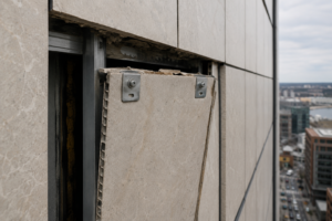
What Makes CMU a Uniquely Difficult Substrate for EIFS
CMU is inherently absorptive and moisture-cycling. It wets and dries unevenly across the wall plane, creating differential movement and vapor pressure conditions that barrier EIFS cannot accommodate.
This is not a defect in the CMU; it is the material’s nature. Applying a barrier cladding system over a reservoir substrate without a drainage plane between them is a specification error, not a construction defect.
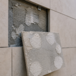
Surface alkalinity, efflorescence and form-release residue on CMU face shells compromise adhesive and base coat bond in ways that standard EIFS substrate prep protocols consistently underestimate. A clean, dry, structurally sound substrate looks adequate on a pre-application checklist.
It is not the same as a substrate prepared to the flatness and surface chemistry requirements that EIFS adhesion actually demands.
ASTM C90 dimensional tolerances for loadbearing concrete masonry units allow face shell thickness variation and overall unit height variation that produce a substrate surface far from the flatness required for compliant adhesive application. Most EIFS manufacturer technical bulletins require substrate flatness within one-quarter inch in ten feet prior to insulation board application.
CMU construction routinely misses that tolerance, particularly at coursing transitions and around openings. The result is voids behind adhesively applied insulation boards that eliminate the uniform bond required for system warranty compliance and, more importantly, create pathways for moisture to track laterally behind the insulation layer without any means of exit.
The mortar joint profile compounds the flatness problem in ways that are easy to overlook during design and nearly impossible to correct after the masonry is complete. Tooled concave joints produce a surface profile that is geometrically incompatible with full-coverage adhesive application.
Flush-cut joints are marginally better but still introduce surface variation that requires either a parge coat or a fluid-applied WRB to bridge before insulation board goes on. Neither the parge coat nor the WRB is free and neither appears in the budget line that justified the EIFS specification in the first place.
When the value engineering conversation arrives, these substrate preparation costs are frequently the first items removed, which is precisely when the assembly begins its trajectory toward a forensic investigation fifteen years later.
Mechanical fastening of insulation board over CMU introduces a different set of problems. Fastener pullout values in CMU face shells vary significantly depending on face shell thickness, block density and whether the fastener lands in a mortar joint or a unit face.
EIFS manufacturers publish minimum pullout requirements, typically in the range of 100 to 150 pounds per fastener depending on wind zone, but field verification of those values in CMU substrates is rarely specified and almost never performed. A fastener that meets pullout requirements in a standard-weight CMU face shell may not meet them in a lightweight unit or in a unit with a thin face shell at the lower end of ASTM C90 tolerance.
That variability is a substrate-specific risk that does not exist to the same degree in concrete or gypsum sheathing applications.
The Moisture Mechanics: How Water Gets In and Where It Goes
Three primary water entry pathways define EIFS-over-CMU failure. The first is penetration through finish coat cracks and impact damage, the failure mode that gets the most attention but is rarely the primary driver of structural damage.
The second is migration through improperly sealed penetrations and terminations, particularly at fenestration rough openings, pipe penetrations and electrical conduit entries where sealant joints are undersized, wrong chemistry or simply missing. The third is vapor drive from interior conditioned space through the CMU and into the insulation layer, a mechanism that dominates in IECC Climate Zones 1 through 3 and in any assembly where the interior is maintained at elevated humidity.
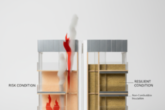
The reservoir effect specific to CMU is the mechanism that makes barrier EIFS so dangerous on this substrate. The masonry wall stores absorbed rainwater and releases it inward under solar-driven vapor pressure, pushing moisture into the insulation board and base coat interface.
Barrier EIFS has no capacity to redirect that moisture. It accumulates.
When moisture reaches the CMU-to-insulation interface without a drainage plane, it tracks laterally along the back face of the insulation board. It saturates CMU cores.
It wicks to embedded steel, including lintels, masonry anchors and shelf angle connections and initiates corrosion cycles that are completely invisible from the exterior until section loss becomes structurally significant. ASTM E331 establishes methodology for water penetration testing of exterior assemblies and ASTM E2568 includes water resistance requirements for PB EIFS systems, but neither standard replicates CMU reservoir conditions.
The testing framework does not capture the failure mode. That gap is a specification problem, not a testing problem.
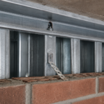
The lintel corrosion pathway deserves specific attention because it is the failure mode most likely to produce structural consequences rather than simply cosmetic or envelope performance problems. Embedded steel lintels in CMU construction are typically coated or galvanized at installation, but that protection is compromised at field cuts, at bearing points where the coating is abraded during installation and at any location where the lintel contacts mortar directly.
Once moisture reaches the lintel through saturated CMU cores, the corrosion cycle begins. Steel corrosion products occupy roughly three times the volume of the original steel, generating expansive pressure that cracks the CMU face shells and mortar joints from the inside.
That cracking is frequently misread from the exterior as shrinkage cracking or settlement and the EIFS finish coat masks it entirely until the expansion is severe enough to telegraph through the lamina. By that point, the lintel has typically lost meaningful section and the repair scope extends well beyond the EIFS assembly.
What the Drainage Mat Actually Does and What It Cannot Do Alone
The drainage mat’s functional role is precise and limited: it creates a capillary break and a three-dimensional drainage cavity between the back face of the insulation board and the CMU substrate. Incidental moisture that breaches the EIFS lamina has a path to drain to a collection and exit point rather than accumulate at the interface.
That is the entire value proposition. It is significant.
It is also not a system solution by itself.
The limitations that specifiers routinely misunderstand are more important than the function. The drainage mat is not a waterproofing membrane.
It does not compensate for missing through-wall flashing. It provides zero benefit if weep screeds are omitted, clogged or terminated above grade without a clear drainage path to the exterior.
A drainage mat installed over bare CMU without a fluid-applied air and water-resistive barrier (WRB) underneath it does not establish the water control layer; it creates a drainage channel that feeds directly into the CMU substrate.
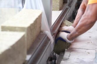
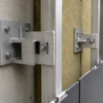
Correct installation sequence matters and is non-negotiable. The fluid-applied WRB goes on the CMU face first, fully covering all mortar joints and surface voids.
The drainage mat installs over the WRB with drainage channels oriented vertically, continuous to the weep screed at each horizontal termination including shelf angles, window heads and base of wall. Insulation board adheres or mechanically fastens over the mat.
Break that sequence anywhere and the drainage plane is compromised.
Compatibility is a separate and underappreciated problem. Entangled-filament mats, dimple mats and mesh-type drainage layers each interact differently with adhesive base coat application.
Using a non-approved drainage layer voids most manufacturer warranties and, more practically, can prevent adequate base coat embedment into the drainage mat surface. ICC AC235 and ASTM E2568 Section 5 define requirements for drainage EIFS systems.
Manufacturer technical data sheets define approved drainage mat products for each specific system. Specifiers need to verify that alignment explicitly in the specification, not leave it to the contractor’s interpretation.
The drainage rate capacity of the mat is a specification variable that rarely receives attention but matters in high-exposure conditions. Entangled-filament drainage mats in the 0.25-inch to 0.
375-inch thickness range provide drainage capacity that is adequate for incidental moisture management. They are not designed to handle bulk water from a failed through-wall flashing condition or a missing end dam.
Specifiers who treat the drainage mat as a backstop for flashing failures are misreading the product’s engineering basis. The mat handles what gets past a properly functioning water control layer.
It does not substitute for one. That distinction needs to be explicit in the specification narrative and in the pre-installation conference documentation, because field crews frequently operate on the assumption that more drainage mat equals more forgiveness on the flashing details.
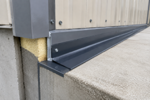
Through-Wall Flashing and Weep Screed Coordination: The Detail That Gets Value-Engineered Out
Through-wall flashing in the CMU backup and the EIFS weep screed at horizontal terminations are not independent details. They are two components of a single drainage circuit.
Through-wall flashing intercepts water that has entered the CMU collar joint or core and directs it to the exterior through weeps. The EIFS weep screed must align with and terminate at the same horizontal plane to complete that circuit.
When they are designed or installed independently, the circuit fails.
Three coordination failures appear repeatedly in forensic investigations. First: through-wall flashing installed at the shelf angle with the EIFS base track set above the flashing termination, creating a moisture trap between the flashing terminus and the base track that has no exit path.
Second: weep screed installed at the correct elevation but without coordination with the through-wall flashing end dam locations, allowing water to bypass the weep and continue laterally inside the assembly. Third: through-wall flashing specified on the structural drawings and EIFS termination detailed on the architectural drawings, with no single drawing set showing both in section simultaneously.
Nobody coordinates what nobody shows together.
The value engineering conversation almost always targets the through-wall flashing end dams and the through-wall flashing extension beyond the shelf angle face. These are small material costs with enormous consequence.
Eliminating or shortening them is a decision that converts a drainage assembly into a moisture collection assembly. That is not a tradeoff; it is a failure waiting to be discovered.
The material selection for through-wall flashing in this assembly also warrants more specification attention than it typically receives. Self-adhered flexible flashing products are common in this application, but their long-term adhesion to CMU substrates depends on surface preparation and primer selection that is rarely specified with the same rigor applied to the EIFS WRB.
A through-wall flashing that debonds from the CMU substrate at the back leg within five years of installation provides no drainage function regardless of how well the EIFS weep screed was coordinated with it. Sheet metal through-wall flashing with sealed end dams is more reliable in CMU applications precisely because it does not depend on adhesive bond to a variable masonry substrate.
The cost premium is real and the specification conversation about that premium is worth having explicitly, because the alternative is a fifteen-year forensic investigation.
Weep screed slot sizing and spacing is a detail that gets standardized in specifications without reference to the drainage mat capacity behind it. Standard open-slot weep screeds at 33-inch centers are adequate for incidental moisture drainage in a properly functioning assembly.
In a high-exposure condition with a south or west wall orientation in a climate with significant wind-driven rain, that spacing may be insufficient to drain the mat cavity without backup. Reducing weep spacing to 16 inches on high-exposure orientations is a low-cost specification adjustment that the forensic record supports.
Base Coat Application Over CMU: Where Field Practice Diverges from Specification Intent
Applying EIFS base coat directly to CMU without a drainage mat or WRB is a code violation under most adopted EIFS specifications and a warranty violation under every major system manufacturer’s technical requirements. It also happens on a significant percentage of projects.
The specification says drainage EIFS. The submittal gets approved.
The WRB and drainage mat arrive on site. Then schedule pressure, crew sequencing problems or simple ignorance results in insulation board going directly over CMU.
The base coat compatibility problem compounds this. CMU surface alkalinity attacks certain base coat formulations over time, degrading bond strength in ways that do not manifest immediately.
A pull-off adhesion test at substantial completion may pass. The same assembly tested five years later, after moisture cycling and alkalinity migration, may not.
This is why ASTM E2568 compliance at installation does not guarantee long-term performance on CMU substrates without the full drainage assembly.
Specifiers who include base coat compatibility verification as a submittal requirement and who require a pre-installation conference that explicitly covers CMU surface preparation, WRB application and drainage mat installation sequence, catch more of these failures before they become building enclosure litigation. That is a specification habit, not a field supervision function.
The submittal review process is where specification intent most frequently gets diluted without anyone making an explicit decision to dilute it. A contractor submits a drainage mat product that is not on the EIFS manufacturer’s approved product list.
The architect reviews the submittal against the specification section for the drainage mat in isolation rather than cross-referencing the EIFS manufacturer’s current technical bulletin. The submittal gets approved with a stamp that says “approved as noted” and a note that says “verify compatibility with EIFS system.
” Nobody verifies. The incompatible drainage mat goes on the building.
The base coat does not achieve full embedment into the mat surface. The system fails its water resistance function at the lamina-to-mat interface and the drainage plane that was supposed to protect the CMU substrate is now a moisture distribution layer instead.
That sequence is not hypothetical. It appears in forensic investigation reports with enough frequency to constitute a recognizable pattern and the correction is straightforward: the specification needs to require that the drainage mat product be identified by manufacturer name and product designation in the EIFS system submittal, not in a separate submittal reviewed independently.
Field mock-up requirements are another specification tool that the forensic record supports more strongly than current practice reflects. Requiring a minimum 4-foot by 8-foot field mock-up that includes the WRB application, drainage mat installation, insulation board adhesion and base coat application over the actual CMU substrate on the project gives the EIFS contractor, the architect and the owner’s representative a visible reference for what correct installation looks like before the full scope of work proceeds.
It also surfaces substrate preparation problems, drainage mat compatibility issues and crew skill gaps before they are replicated across thousands of square feet of building façade.
What the Next Generation of EIFS-Over-CMU Specifications Needs to Include
The forensic record on mid-2000s to mid-2010s EIFS-over-CMU assemblies is now large enough to identify exactly which specification gaps produce which failure modes. Omitted drainage mat produces reservoir accumulation at the insulation interface.
Uncoordinated through-wall flashing and weep screed produces trapped moisture at shelf angles. Unapproved drainage mat products produce base coat delamination.
Inadequate CMU surface preparation produces adhesion failure that looks like impact damage from the exterior.
Specifiers who want to use EIFS over CMU and produce a performing assembly need to treat the drainage mat, the WRB, the through