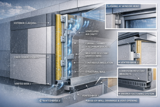
ACM vs. Solid Aluminum vs. Steel Plate: A Specifier’s Technical Comparison of Fabricated Metal Panel Systems for Commercial Rainscreen Applications
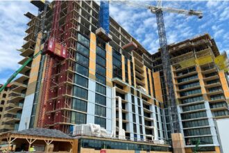
A mid-rise mixed-use project in suburban Maryland. Eight-story building, aluminum subframe already fabricated and delivered to site, submittal approved.
The original specification called for ACM with a polyethylene core and late in the CD phase the owner’s representative approved a substitution to an FR-core product from a different manufacturer on the basis of a $0.40 per square foot cost delta. Nobody re-reviewed the flatness tolerances.
The approved FR-core system published a ±0.025-inch flatness tolerance over a 48-inch span; the subframe attachment spacing had been coordinated around the original manufacturer’s ±0. 040-inch tolerance.
Three elevations came in with visible oil-canning. The remediation program ran well into six figures.
This scenario is composite but not hypothetical. Building envelope consultants see this pattern repeatedly and it almost always originates in the same place: a material substitution approved on cost alone, without facade engineer re-review of the downstream fabrication consequences.
Why Metal Panel Material Decisions Are Made at the Wrong Phase
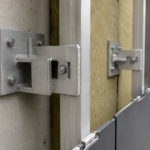
Material type is routinely deferred to DD or CD phase, after subframe geometry and attachment spacing are already locked into the coordination model. By the time a contractor proposes a substitution, the structural logic of the facade has already been built around assumptions that may not survive the switch.
Schematic-phase cost comparisons treat ACM, solid aluminum and steel plate as interchangeable line items despite fundamentally different fabrication logics, stiffness profiles and joinery requirements.
Value engineering substitutions frequently move forward without facade engineer re-review of flatness tolerances or joinery geometry. That gap is where remediation budgets are born.
The problem is structural to how facade systems get procured. A general contractor pricing a GMP in late SD phase pulls unit costs from subcontractor databases that assign a single square-foot number to “metal panel” without distinguishing between a 3mm solid aluminum system requiring back-stiffening and an ACM system that achieves equivalent flatness performance at lower weight and cost.
Those are not the same product and they do not share the same subframe requirements. When the facade engineer is not in the room during that pricing conversation, the distinction disappears into a line item.
The specification itself compounds the problem. CSI MasterFormat places composite wall panels under Division 07 42 43 and metal wall panels under Division 07 42 13, but specifiers routinely apply a single performance section to all three systems despite their distinct performance profiles.
A performance specification written to accommodate all three materials simultaneously will be written to the least restrictive tolerance and the broadest material description, which is precisely the condition that enables substitution disputes. The central argument here is straightforward: material-specific tradeoffs must enter the conversation at SD phase, not during submittal review when the subframe is already on a truck.
The facade engineer’s involvement at schematic phase costs a fraction of what a single remediation program costs and the Maryland project is not an outlier. It is a representative data point from a pattern that repeats across project types, climate zones and delivery methods.
Core Composition and Base Material: What You’re Actually Specifying
ACM consists of two aluminum skins, typically 0.020 to 0. 024 inches thick, bonded to a core material.
The core is the primary fire and structural variable, not the skin. Polyethylene cores offer superior flatness performance and ease of fabrication.
FR cores reduce combustible content but alter the panel’s bending stiffness and thermal expansion behavior in ways that affect joinery clearances. Mineral-filled cores push fire performance further but introduce weight penalties that affect connection design.
Solid aluminum is monolithic sheet, typically 3mm to 6mm (0.118 to 0. 236 inches) with no core variable.
Structural behavior is entirely thickness-dependent. Thicker sheet resists oil-canning but adds dead load and cost; thinner sheet demands back-stiffening or tighter attachment grids.
Steel plate for rainscreen applications typically runs 14 to 12 gauge using carbon or Galvalume substrate. The stiffness-to-thickness ratio exceeds aluminum at equivalent gauges, which is a real advantage for large-format panels.
However, steel introduces galvanic compatibility requirements with aluminum subframes and corrosion management obligations that aluminum systems do not carry.
Specifiers should cite ASTM B209 for aluminum sheet and plate and ASTM A653 for zinc-coated steel sheet explicitly in Division 07 sections. Describing a panel as simply “aluminum” without core designation or thickness range is an incomplete material description and a standing invitation to substitution disputes.
A specification that reads “aluminum composite panel, 4mm nominal” without identifying the core type, the skin thickness and the applicable flatness tolerance document is functionally an open substitution clause. Any product that is nominally 4mm and nominally aluminum qualifies, regardless of whether its fabrication logic is compatible with the approved subframe geometry.
Specifiers who have inherited master specifications from firm libraries should audit those sections specifically for core designation language, because older master specs written before post-Grenfell scrutiny intensified frequently omit it entirely. The AAMA 2605 coating requirement may be present and the wind load performance requirement may be present, but the core designation is missing and that is the variable that drives the most consequential downstream differences.
Fire Core Classification: Where Post-Grenfell Scrutiny Has Permanently Changed the Calculus
Pre-Grenfell North American practice frequently specified ACM with PE cores on mid-rise projects under the assumption that NFPA 285 assembly testing provided sufficient coverage. Post-2017 scrutiny has exposed the limits of that assumption and the limits were always structural: NFPA 285 tests a specific assembly configuration and approval does not transfer to field-modified configurations, different subframe geometries or altered cavity depths.
IBC 2021 Section 1402.5 governs combustible exterior wall finish materials and requires that ACM assemblies on buildings of Type I through IV-A construction meet NFPA 285 test criteria. ACM with a PE core cannot achieve NFPA 285 compliance in most rainscreen configurations.
FR and mineral-filled cores can, but they carry different fabrication constraints that affect routing geometry, corner return radii and panel weight.
Solid aluminum and steel plate carry no combustible core variable. For projects subject to heightened AHJ scrutiny or owner-driven fire risk requirements, that simplification has real value.
The submittal process is shorter, the compliance narrative is cleaner and the liability exposure during construction administration is lower. A facade engineer reviewing submittals on a solid aluminum or steel plate assembly does not need to verify that the installed cavity depth matches the NFPA 285 test configuration, does not need to confirm that the subframe geometry falls within the tested assembly parameters and does not need to track whether field modifications during installation have taken the assembly outside its tested configuration.
Each of those verification steps is a real cost in construction administration time and each represents a gap where a PE-core ACM assembly can fall out of compliance without anyone catching it until an AHJ inspection or, worse, a fire event.
Jurisdictions including New York City, Los Angeles and Chicago have applied enhanced scrutiny to ACM submittals above 40 feet regardless of IBC baseline and local amendments frequently exceed the model code. New York City’s Local Law 26 of 2004 and subsequent amendments have driven ACM compliance requirements that predate the IBC 2021 baseline by nearly two decades.
Los Angeles Department of Building and Safety has issued specific guidance on ACM submittals following California’s adoption of enhanced fire provisions. Specifiers must verify current local requirements; do not assume the 2021 IBC baseline applies without amendment review.
The UK’s Building Safety Act 2022 banned combustible cladding above 18 meters following the Grenfell Tower investigation. North American regulatory trajectory is not identical, but the direction is not ambiguous.
Specifiers who are writing five-year master specifications should build FR or mineral-filled core requirements into their baseline ACM sections now rather than revising them reactively when a local amendment catches them mid-project.
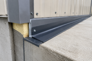
Flatness Tolerances and Oil-Canning: The Aesthetic Risk No Spec Section Eliminates
Oil-canning is a function of material stiffness, panel aspect ratio, attachment point count and thermal movement. Each material manages these variables differently and the interactions are not linear.
ACM’s composite construction resists oil-canning at larger panel sizes than equivalent-gauge solid aluminum. The skin-core-skin sandwich creates a moment of inertia that neither material achieves independently at comparable weight.
Industry practice targets ±0.030 inches over 48 inches as a flatness benchmark, but this figure is not standardized across AAMA 508-07, which governs pressure-equalized rainscreen wall cladding systems. AAMA 508-07 leaves flatness tolerances largely to manufacturer-published values, which means specifiers who do not explicitly invoke a manufacturer’s published tolerance document are accepting whatever tolerance the approved product carries.
That is a specification gap with visible consequences. The Maryland project’s remediation program was a direct product of that gap: the substituted product’s published tolerance was tighter than the original product’s tolerance, the subframe had been spaced for the original product’s tolerance and nobody in the substitution review chain connected those two facts before fabrication began.
Solid aluminum is the most susceptible of the three materials to oil-canning at standard thicknesses. At 3mm, a flat panel in a 4-by-8-foot format will telegraph thermal movement and attachment stress as visible waviness under raking light conditions.
The effect is most pronounced on west and south elevations where afternoon sun creates steep incident angles and it is most visible on dark colors where the contrast between highlight and shadow is sharpest. Mitigation options include back-stiffening with aluminum extrusions, reducing panel size or increasing sheet thickness to 4mm or 6mm.
All three are cost adders that rarely appear in SD-phase budgets. Back-stiffening extrusions add fabrication labor and material cost, typically $2.00 to $4.
00 per square foot depending on extrusion profile and spacing. Reducing panel size increases the joint count, which affects the visual rhythm of the facade and may conflict with the design intent.
Increasing thickness to 6mm on a large facade adds meaningful dead load that the subframe and primary structure must accommodate.
Steel plate’s higher inherent stiffness makes it the most forgiving of the three for large-format applications. The tradeoff is thermal expansion differential with aluminum subframes.
Steel expands at approximately 6.5 millionths per inch per degree Fahrenheit; aluminum expands at approximately 12. 9 millionths.
That differential across a 10-foot panel span over a 100-degree seasonal temperature range produces meaningful movement that slotted connections must accommodate. A 10-foot steel panel will expand approximately 0.078 inches over a 100-degree range; an aluminum subframe spanning the same distance will expand approximately 0.
155 inches. The net differential of approximately 0.077 inches must be absorbed by the connection detail and a connection designed for aluminum panel thermal movement will be undersized for this differential.
Detailing that connection correctly requires explicit coordination between the panel fabricator and the subframe engineer and it rarely gets that attention at the right phase.
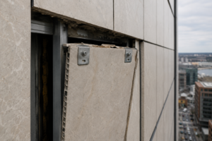
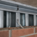
Joinery Geometry and Fabrication Logic
Each material imposes a different fabrication logic on the joint system and those logics are not interchangeable without consequence to the subframe geometry.
ACM routs and folds. The core is removed in the bend zone and the aluminum skins fold to form returns, flanges and corner conditions.
That process enables tight-radius corners and integrated drainage features, but it also means the panel’s structural integrity at the perimeter depends on the quality of the fold and the adhesive bond at the fold line. Specifiers should require that ACM fabricators demonstrate compliance with ASTM C1396 or equivalent for bond integrity at routed corners, particularly in assemblies subject to wind uplift above 25 psf design pressure.
The routing depth is a critical variable that fabricators control in-house and a router set 0.005 inches too deep will cut through the interior skin and compromise the fold entirely. That defect is not visible in the finished panel and will not appear in a standard visual inspection.
Specifiers on projects with high wind uplift requirements should consider requiring destructive testing of sample corners from each production run, with minimum peel strength values stated in the specification. That requirement is not standard practice, but it is defensible on projects where wind design pressures at corners and edges exceed 30 psf.
Solid aluminum bends but does not rout. Corner returns require mechanical fastening or welded construction, both of which add cost and fabrication lead time.
The absence of a core means there is no bond line to fail, which is a genuine durability advantage in high-humidity or coastal environments where adhesive degradation over time is a legitimate concern. Mechanically fastened returns on solid aluminum panels should specify stainless steel fasteners to avoid galvanic corrosion at the connection and the fastener pattern should be designed to transfer wind uplift loads without relying on the coating system for structural continuity.
Welded solid aluminum corners require post-weld finishing to achieve a surface quality acceptable for painted finishes and that finishing labor is a cost that estimators frequently undercount when pricing solid aluminum against ACM on a square-foot basis.
Steel plate requires different tooling entirely. Bending radii are larger than aluminum at equivalent gauge, which affects the visual profile of panel returns and corner conditions.
A 12-gauge steel panel will have a minimum inside bend radius of approximately 0.125 inches using standard press brake tooling; an ACM panel can achieve a near-zero inside radius at the routed fold. That difference is visible at panel corners and must be accounted for in the design detailing.
Welded connections are more common and more reliable than in aluminum, but weld quality must be specified explicitly, including grind-and-finish requirements for exposed welds in painted assemblies. A specification that requires “welds ground smooth” without defining a surface profile standard will produce inconsistent results across fabricators.
Reference AWS D1.2 for aluminum structural welding and AWS D1. 1 for steel and specify the surface finish class required for painted assemblies in the same section.
Long-Term Finish Performance and Maintenance Expectations
All three materials depend on coating systems for long-term performance and the coating specification matters more than the substrate in many service environments.
PVDF (polyvinylidene fluoride) coatings applied to AAMA 2605 standards represent the baseline for commercial exterior applications. AAMA 2605 requires 70 percent PVDF resin content, minimum film thickness and performance thresholds for chalk, fade and humidity resistance over a 10-year test period.
Specifiers who accept AAMA 2604 coatings on the basis of cost savings are accepting a meaningfully lower service life, particularly in IECC Climate Zones 1 through 3 where UV exposure and thermal cycling are severe. The cost differential between AAMA 2604 and AAMA 2605 coatings at the factory is typically $1.50 to $3.
00 per square foot. The cost of recoating or replacing panels that have failed prematurely in a Climate Zone 2 coastal environment is an order of magnitude higher and the disruption to building operations during a facade recoating program is a cost that never appears in the original value engineering analysis.
Specifiers should also require that color and gloss retention test data be submitted with the coating certification, not just the AAMA 2605 certificate. Two products can both carry AAMA 2605 certification and perform differently in field conditions and the test data will show that difference where the certificate alone will not.
Steel substrates require additional corrosion protection beneath the coating system. Galvalume substrate provides baseline galvanic protection, but cut edges at panel perimeters, drilled holes and field modifications expose bare metal.
Specifying field touch-up protocols and edge sealing requirements is not optional for steel panel assemblies in coastal or high-humidity environments. That language belongs in Division 07 42 13 and it is frequently absent.
A steel panel assembly installed without edge sealing requirements in a ASHRAE 169-2021 moisture zone 5A or higher environment will begin showing rust bleed at panel edges within three to five years of installation. That bleed stains the joint sealant and the panel face below each horizontal joint and it is not correctable without panel removal.
The touch-up paint specified for field use should be a two-component epoxy primer compatible with the factory PVDF topcoat and the specification should require that the panel fabricator provide the touch-up system and application instructions as part of the submittal package, not as a post-installation afterthought.
ACM and solid aluminum do not carry the same edge corrosion risk, but they are not maintenance-free. Anodized finishes, while durable, are more difficult to repair in the field than PVDF coatings and are inappropriate for assemblies with frequent panel replacement requirements.
Anodized color matching in the field is effectively impossible; a replacement panel anodized in a different production run will not match the original panels under most lighting conditions. For assemblies where individual panel replacement is anticipated, PVDF-coated panels are the correct specification regardless of the initial cost premium over anodized finishes.
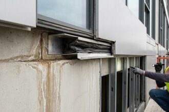
Making the Selection Before the Subframe Is Already Fabricated
The practical recommendation is this: bring the facade engineer into the material selection conversation at SD phase, before attachment spacing is coordinated, before the subframe is priced and certainly before a contractor has any basis for a substitution request. The cost differential between ACM, solid aluminum and steel plate is real but manageable when it is priced into the schematic budget.
It becomes a remediation program when it surfaces during submittal review.
Specifiers should also close the AAMA 508-07 flatness gap explicitly.