
Integrating Cavity Insulation and Firestopping for Optimal Wall Performance
A mid-rise wood-frame project in the Pacific Northwest failed its final inspection when the fire marshal identified open cavities at floor-line penetrations where spray foam insulation had been installed without compliant firestopping. The contractor had assumed the expanding foam served dual duty as both thermal fill and fire barrier. That assumption cost the owner six weeks and a remediation budget that ran well into five figures.
- Integrating Cavity Insulation and Firestopping for Optimal Wall Performance
- Cavity Insulation and Firestopping Are Not the Same Thing
- The Regulatory Framework Governing Both Systems
- Where the Systems Physically Intersect in Wall Assemblies
- Material Compatibility: What Works Together and What Does Not
- Sequencing and Trade Coordination on the Job Site
- Inspection, Documentation and the Closeout Package
- Coordinating the Specification Before the First Stud Goes Up
The misconception is not rare. It surfaces on projects across every construction type and it almost always originates from the same place: two separate subcontractors, two separate scopes and nobody at the table who understood both.
Cavity Insulation and Firestopping Are Not the Same Thing
Cavity insulation exists to manage heat flow and, in some assemblies, to attenuate sound. Firestopping exists to prevent fire and combustion gases from migrating through concealed spaces and killing occupants in adjacent compartments. These are categorically different performance obligations governed by entirely different regulatory frameworks and conflating them is a specification and field coordination failure.
Most insulation materials, including both open-cell and closed-cell spray polyurethane foam, are not independently listed as firestop systems. This is not a gray area. A material’s physical properties, whether it expands, whether it chars or whether it has a low flame spread index, do not qualify it as a firestop system.
IBC Section 718 draws a clear line between draftstopping, firestopping and insulation requirements in concealed spaces. These are distinct provisions with distinct compliance thresholds.
The concept of system listing is the piece that most insulation subcontractors miss entirely. A firestop assembly must be tested and listed as a complete system under UL 1479 or ASTM E814. The listing covers specific materials in specific configurations at specific annular spaces. Substituting one component, including the insulation fill material, can invalidate the entire listed assembly.
That is not a technicality. That is how the test standard works.
Field conversations with firestop manufacturers’ technical representatives consistently surface the same pattern: an insulation subcontractor installs foam to the underside of the floor deck, the firestop applicator arrives two weeks later and cannot access the floor-line cavity without cutting out the foam and the general contractor absorbs the cost of both the remediation and the schedule impact. The listed system documentation for a UL W-L series assembly specifies the exact sequence of component installation. When that sequence is violated, the installer cannot certify the assembly to the listed design number and the special inspector has no basis for sign-off.
The downstream consequence is a closeout package with a compliance gap that either gets papered over or triggers the kind of destructive investigation that no owner wants to fund after occupancy.
The Regulatory Framework Governing Both Systems
IBC Chapter 7 is the primary code driver for firestopping in wall assemblies. Section 714 governs penetrations through fire-resistance-rated assemblies and requires through-penetration firestop systems that maintain the fire-resistance rating of the assembly being penetrated. Section 715 addresses fire-resistant joint systems at construction joints, including the floor-line joints in platform-frame construction that created the failure described above.
NFPA 101 adds a parallel compliance layer in certain occupancy types, particularly healthcare and educational facilities, where the Life Safety Code imposes firestopping requirements independent of the IBC. On projects subject to both codes, the more stringent provision governs. Do not assume IBC compliance is sufficient without checking the applicable edition of NFPA 101 and its local adoption status.
The 2021 edition of NFPA 101, Section 8.3, carries specific requirements for smoke compartmentation and through-penetration protection that can exceed IBC Chapter 7 thresholds in Group I-2 occupancies. A hospital project that satisfies IBC Section 714 may still fail a Joint Commission survey if the NFPA 101 requirements were not independently verified during design.
The test standards that govern listed firestop system performance are UL 1479 and ASTM E814. Both define the F-rating, which is the time in hours the firestop system prevents flame passage and the T-rating, which is the time before the unexposed side of the assembly reaches a temperature rise of 325 degrees Fahrenheit above ambient. T-ratings matter in occupancies where personnel may be in contact with the assembly on the unexposed side. A common specification error is requiring only an F-rating in occupancies where a T-rating is warranted.
In a corridor wall assembly adjacent to an occupied space, a firestop system with an F-2 rating but no T-rating can allow the unexposed face of the wall to reach temperatures that cause injury or secondary ignition before the rated period expires. The spec must address both ratings explicitly for each condition.
Energy codes run on a completely separate track. IECC 2021 Section C402.2 drives cavity insulation requirements for commercial occupancies based on climate zone and assembly type. These requirements do not reference firestop performance.
The two compliance paths must converge at the wall assembly level and that convergence requires deliberate coordination at the specification stage, not improvisation in the field. In Climate Zone 6 and above, continuous insulation requirements for above-grade walls can drive designers toward exterior foam plastic systems that introduce NFPA 285 compliance obligations simultaneously with the IBC Chapter 7 firestopping requirements. Managing both compliance tracks on the same wall assembly without a coordinated specification is a reliable path to field conflicts and inspection failures.
Where the Systems Physically Intersect in Wall Assemblies
Four locations in typical wall assemblies concentrate the risk of firestopping and insulation conflicts. Understanding each one changes how you write the spec and how you run the pre-construction meeting.
The first is the floor-line cavity in platform-frame construction. The horizontal blocking at each floor level is the required firestop location under IBC Section 718.4 and it sits directly within the stud cavity that the insulation contractor intends to fill. When insulation is installed before firestopping, the blocking location is buried, the firestop contractor cannot access the cavity properly and the inspection cannot be completed without destructive investigation.
This is exactly the sequence failure that produced the opening scenario. On a typical five-story wood-frame multifamily project, there may be several thousand linear feet of floor-line firestop condition distributed across exterior and corridor walls. Each one of those locations is a potential inspection failure if the sequencing is not enforced as a hard schedule gate.
The cost of accessing and remediating even a fraction of those locations after insulation installation is installed is substantial and the schedule impact compounds when the building inspector requires a reinspection hold before framing can be enclosed.
The second location is the top-of-wall and ceiling interface, where stud cavities open into ceiling plenum spaces. In assemblies where the plenum is used as a return air path, this intersection has both firestopping and air barrier implications simultaneously. IBC Section 718.4 requires draftstopping in concealed spaces of combustible construction and the top-plate condition in a wood-frame wall opening into a plenum return is a specific trigger for that requirement.
The insulation contractor filling the stud cavity to the top plate does not automatically address the draftstop condition at the plenum interface. A separate listed assembly or compliant draftstop material is required and the spec must identify which trade is responsible for that work.
The third is electrical and mechanical penetrations through insulated cavity walls. Insulation compressed around a conduit or pipe does not constitute a listed through-penetration firestop. The annular space must be addressed with a system listed under UL 1479 for that specific penetrant type, wall construction and annular space dimension.
A 3/4-inch EMT conduit penetrating a one-hour rated wood-frame wall requires a listed system that names that conduit type, that wall construction and that annular space. The UL Product iQ database contains hundreds of W-series design numbers for wood-frame wall penetrations and the correct one must be identified in the specification before the electrician and the firestop applicator arrive on the same floor. Leaving the system selection to the firestop applicator in the field is a coordination abdication that produces inconsistent results across a project.
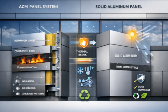
The fourth is the spandrel zone in curtain wall assemblies. NFPA 285 evaluates fire propagation characteristics of exterior non-load-bearing wall assemblies as complete systems. The insulation type, thickness and placement within the spandrel cavity are components of that tested assembly.
IBC Section 2603.5 imposes specific ignition barrier and thermal barrier requirements for foam plastic insulation in exterior walls. Substituting a different insulation product mid-project, even one with equivalent thermal performance, can invalidate the NFPA 285 compliance of the entire assembly. This is a change order waiting to happen if the spec does not lock down the tested assembly configuration.
Curtain wall manufacturers who hold NFPA 285 test reports for their assemblies will specify the exact insulation product, density and thickness used in the tested configuration. Any deviation from those parameters requires either a new test or a fire engineer’s analysis demonstrating equivalency and neither option is inexpensive or fast.
Material Compatibility: What Works Together and What Does Not
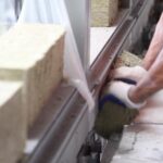
Mineral wool (stone wool or slag wool) batts carry a significant coordination advantage at firestop locations because they comply with ASTM E136 as non-combustible materials. Certain UL-listed floor-line firestop assemblies in the W-L-1000 series for wood-frame construction incorporate mineral wool as a component. When the insulation specification and the firestop specification align on mineral wool at floor lines, the same material can serve the thermal fill function within a listed assembly.
This is the most defensible coordination approach available in light wood-frame construction and it is underused. Mineral wool’s non-combustibility also simplifies the ignition barrier question in wall assemblies where foam plastic insulation would otherwise require a 15-minute thermal barrier under IBC Section 2603.4. Specifying mineral wool at floor-line and penetration conditions eliminates an entire category of compliance conflict and reduces the number of listed systems the firestop applicator must manage on site.
Closed-cell SPF has better performance characteristics than open-cell at firestop-adjacent locations. Its higher density and low vapor permeability reduce the risk of gas migration and some manufacturers hold UL-listed system designs that incorporate closed-cell SPF as a component in specific configurations. However, the SPF alone does not constitute the listed system.
A listed intumescent or cementitious overlay at penetrations and floor lines is still required and the listed system documentation governs the acceptable SPF thickness, density and application conditions. Closed-cell SPF applied at a density below the listed minimum or at a thickness outside the listed range, is not a compliant component regardless of the manufacturer’s general product approvals. The applicator must have the specific listed system design number in hand before installation begins and the special inspector must verify the installed density and thickness against that listing.
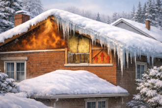
Open-cell SPF fails at floor-line applications without significant supplemental firestopping. Its lower density and vapor permeability make it unsuitable as a firestop fill and no credible listed system relies on open-cell SPF as the primary fire barrier component at a floor-line cavity. Open-cell SPF also presents a specific problem in cold climates where vapor drive can cause moisture accumulation within the foam matrix at floor-line blocking locations, degrading both the thermal performance and the long-term integrity of any supplemental firestop material applied over it.
Specifying open-cell SPF in Climate Zone 5 and above requires a vapor retarder analysis and that analysis often reveals that the floor-line condition is incompatible with open-cell SPF regardless of the firestopping question.
Fiberglass batt insulation presents a different problem. Kraft paper and foil facings are combustible and must be removed or covered at firestop locations. Unfaced fiberglass can be a component in some listed assemblies, but the facing condition is a specific parameter in the listing.
Intumescent firestop products placed against faced fiberglass batts require verification of chemical compatibility and compression performance against the manufacturer’s listed system documentation. Assuming compatibility because both materials are present in the same cavity is not adequate. Field observations on multifamily projects have documented cases where intumescent wrap strips installed over kraft-faced batts failed to expand correctly during testing because the facing material compressed the wrap and prevented full intumescent reaction.
The result was a listed assembly that could not perform to its rated F-value because a facing condition not covered by the listing was present in the field.
Sequencing and Trade Coordination on the Job Site
The correct installation sequence is non-negotiable: rough-in inspections first, then firestop installation and inspection, then insulation installation. Reversing any step in that sequence creates conditions that cannot be inspected without destructive investigation.
Responsibility boundaries are where coordination breaks down most often. Firestopping is typically carried by the general contractor as a direct scope item or assigned to a specialty subcontractor. Insulation is a separate subcontract.
Neither party has a contractual obligation to coordinate with the other unless the specification explicitly requires it. The spec must assign coordination responsibility, require a pre-installation meeting that includes both trades and the building inspector and establish hold points at which firestop inspection must be completed before insulation installation proceeds. On projects where the general contractor does not enforce those hold points, the insulation subcontractor has no financial incentive to wait.
The foam crew works by the square foot, not by the inspection cycle and a floor that can be closed out in a day will be closed out in a day if nobody stops it.
The specification-to-field gap at this intersection is severe. A well-written Section 07 84 00 can identify every required listed system by UL design number, specify the correct sequence and assign inspection hold points. That same spec can be completely ignored on a fast-track project where the framing crew, the foam crew and the firestop applicator never occupy the site at the same time.
Project managers need to treat firestop inspection as a hard schedule gate, not a paperwork exercise at closeout. The practical mechanism for enforcing that gate is a floor-by-floor inspection sign-off sheet that the building inspector, the special inspector and the general contractor’s superintendent all sign before insulation installation is authorized on that floor. That sheet becomes part of the project record and creates accountability at the field level that a specification paragraph alone cannot produce.
Some general contractors on larger multifamily projects have begun incorporating that sign-off requirement into their subcontract exhibits, which gives the superintendent contractual authority to stop the insulation crew without escalating to project management.
Inspection, Documentation and the Closeout Package
Special inspection requirements for firestopping under IBC Chapter 17 are frequently underenforced. Section 1705.17 requires special inspection of through-penetration firestop systems and fire-resistant joint systems in certain occupancy types and construction classifications. The inspector must verify that the installed system matches the listed assembly by design number, that the specific materials used match the listing and that annular space dimensions fall within the listed range.
In practice, many special inspectors on wood-frame multifamily projects lack the product-specific training to verify those parameters in the field. An inspector who cannot distinguish between a UL W-L-1001 and a W-L-1025 assembly cannot confirm that the correct listed system was installed. The statement of special inspections prepared under IBC Section 1705.17 should require that the special inspection agency demonstrate specific firestop product knowledge, not just general building inspection credentials.
Documentation requirements are specific. The closeout package must include the UL design number for each firestop condition, the installer’s certification, the inspection record and photographic documentation of each installed assembly before concealment. On projects where insulation is installed before firestopping is inspected, that photographic record does not exist.
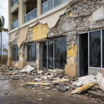
The project is then in a position of either making representations about compliance that cannot be verified or opening the assembly. Some project teams have attempted to satisfy this requirement with post-installation photographs taken through small access openings cut in the insulation, but a photograph of a partial cavity view does not constitute documentation of a complete listed assembly installation. The building official has full authority to require destructive investigation when documentation is inadequate and on projects where that authority is exercised after drywall is installed, the remediation cost is compounded by finish work removal and replacement.
Owners and their legal counsel are increasingly aware of this gap. Latent firestopping deficiencies have produced significant liability exposure on multi-family and mixed-use projects where post-occupancy fire events revealed uncompleted or incorrectly installed firestop work behind finished walls. Several jurisdictions have seen litigation in which the absence of a complete firestop closeout package was treated as evidence of a systemic installation failure, shifting the burden of proof to the contractor to demonstrate that compliant work was performed.
A complete, floor-by-floor photographic record with inspector sign-offs is the only documentation that reliably withstands that scrutiny.
Coordinating the Specification Before the First Stud Goes Up
The single most effective intervention is a coordinated specification that treats the wall assembly as a single system with four control layers, all of which must be addressed simultaneously. The thermal control layer drives the insulation specification. The fire-resistance rating of the assembly drives the firestop specification.
Where those two sets of requirements intersect physically, the specification must name the listed assembly by design number and identify which trade installs which component in which sequence.
Architects who write Section 07 21 00 (Thermal Insulation) and Section 07 84 00 (Firestopping) in isolation, without cross-referencing the physical intersection conditions, are writing specifications that will fail in the field. The detail set must show the firestop condition at the floor line, at penetrations and at the spandrel zone with enough specificity that the installer can identify the required listed system without interpretation. A floor-line detail that shows blocking with a note reading “firestop per code”