

EIFS in High-Wind and Hurricane Zones: What Specifiers Need to Know About Impact Resistance, Drainage Design and Code Compliance
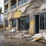
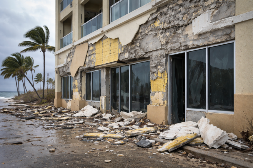
After Hurricane Ian made landfall in September 2022, post-storm assessments of commercial buildings along Florida’s Lee County coastline documented repeated EIFS failures that shared a common thread: drainage-plane assemblies specified piecemeal, with impact-rated finishes applied over base coat systems never tested to Miami-Dade or Florida Product Approval standards. The failures were not an indictment of EIFS as a cladding category.
- EIFS in High-Wind and Hurricane Zones: What Specifiers Need to Know About Impact Resistance, Drainage Design and Code Compliance
- Why Post-Hurricane Scrutiny Is Forcing a Specification Reset
- Understanding Exposure Categories and Wind Speed Thresholds That Govern Specification Decisions
- Impact Resistance Requirements: What “Impact-Rated” Actually Means for an EIFS Assembly
- Drainage-Plane Design: The Detail Decisions That Determine Field Performance
- Air Barrier Continuity in High-Wind Assemblies: The Overlooked Failure Mode
- Thermal Performance Under Coastal Conditions: Effective R-Value Is Not Nominal R-Value
They were an indictment of how the system had been specified, detailed and documented. That distinction matters enormously for every architect and contractor currently evaluating EIFS on a coastal commercial project under today’s code environment.
Why Post-Hurricane Scrutiny Is Forcing a Specification Reset
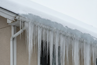
Post-Ian and post-Ida forensic reviews consistently identified detailing failures, not material failures, as the primary driver of water intrusion and cladding loss on commercial buildings clad with EIFS. The base coat cracked.
Drainage planes terminated at window sills without proper integration. Weep screeds were omitted or blocked with sealant.
None of these are inherent weaknesses of EIFS as a system; all of them are specification and execution failures that would have been prevented by current code compliance.
Florida Building Code 8th Edition Section 1403 (Weather Protection) and Section 1609 (Wind Loads) have tightened requirements in ways that legacy EIFS specifications, many written to pre-2010 standards, simply do not satisfy. Code officials and insurance underwriters in coastal Florida counties are now requesting Florida Product Approval documentation at permit submission.
That is a new administrative burden most specifiers were not managing five years ago.
The scrutiny creates a real opportunity. EIFS specified correctly, with impact-rated assemblies, properly detailed drainage and current FPA documentation, can outperform alternative claddings on cost, thermal performance and code compliance simultaneously.
The system is not the problem. The specification is.
What the forensic record from Ian specifically shows is that the failures clustered around a predictable set of conditions: projects where the EIFS scope was divided between a general contractor-supplied air barrier subcontractor and a separate EIFS applicator, with no single party responsible for the continuity of the assembly across transitions. Window head flashings terminated into the drainage cavity without positive attachment to the WRB.
Base tracks were set directly on concrete slabs without through-wall flashing beneath, creating a capillary path that bypassed the drainage plane entirely. These are not obscure detailing conditions.
They appear in every major EIFS manufacturer’s published installation guidelines. The gap was not knowledge; it was accountability and accountability starts in the specification.
Insurance underwriters operating in coastal Florida markets, particularly those writing commercial property policies in Lee, Collier and Charlotte counties, have begun requiring pre-construction envelope commissioning documentation as a condition of coverage on projects above a certain replacement value threshold. That shift is consequential.
It means the specifier’s documentation decisions now have direct financial implications for the owner that extend beyond permit approval into the insurance market. Specifiers who understand that dynamic are better positioned to make the case for the additional specification effort that coastal EIFS assemblies require.
Understanding Exposure Categories and Wind Speed Thresholds That Govern Specification Decisions
Coastal Florida is not a single design condition. ASCE 7-22 wind speed maps define ultimate design wind speeds (Vult) by geography and coastal Florida markets routinely fall in the 160 to 185 mph Vult range.
That range triggers cladding assembly requirements that are categorically different from anything an inland project would face.
Exposure Category D applies to sites on open terrain near large bodies of water, including tidal inlets and shorelines. Exposure Category C, which governs open terrain with scattered obstructions, is frequently misapplied to coastal sites that should be classified as D.
The distinction is not academic. Category D produces substantially higher design pressures and confirming exposure category requires a site-specific assessment, not a regional map lookup.
Wind-driven rain test pressure thresholds under ASTM E331 and ASTM E1105 are directly tied to calculated design wind pressures. A specifier must confirm that the test pressure at which a specific EIFS assembly has been evaluated matches or exceeds the project’s calculated design pressure.
Referencing a system evaluated at 6.24 psf when your calculated design pressure is 9. 0 psf is a specification error that will not survive a code review in Lee or Collier County.
Risk Category classification compounds this. IBC Table 1604.5 distinguishes Risk Category II from III and IV; hospitality and multifamily projects often fall in different categories than institutional buildings on the same block.
Higher risk categories increase load factors. The cladding assembly must be selected against the correct design pressure, not a generic regional assumption.
The exposure category misclassification problem is more widespread than most specifiers acknowledge. A four-story hotel on a barrier island with unobstructed fetch across open water to the west is a Category D site by any reasonable reading of ASCE 7-22 Section 26.7. The same building type three miles inland, behind a line of low-rise commercial development, may legitimately qualify as Category C.
The difference in calculated design pressure between those two classifications, applied to the same building geometry and wind speed, can exceed 20 percent. That margin determines whether a tested EIFS assembly is code-compliant or not and it is established by the structural engineer of record, not by the EIFS specifier.
The specifier’s job is to obtain the confirmed exposure category and design pressures from the structural engineer before selecting a basis-of-design system, not after.
ASCE 7-22 also introduced changes to the directional factor Kd and the ground elevation factor Ke that affect calculated pressures relative to earlier editions. Projects permitted under the Florida Building Code 8th Edition are subject to ASCE 7-22 wind provisions.
Specifications that reference wind pressure thresholds derived from ASCE 7-16 or earlier are not current and the delta between editions is not trivial in high-velocity hurricane zones. Confirming the edition of ASCE 7 that governs the project is a basic coordination step that should happen at the specification outline stage.
Impact Resistance Requirements: What “Impact-Rated” Actually Means for an EIFS Assembly
This is where I see the most consequential specification errors on coastal commercial projects. Impact resistance in EIFS is a function of the base coat and mesh combination.
The finish coat contributes essentially nothing to impact performance. Specifying a heavy-duty finish over a standard base coat and mesh does not produce an impact-rated assembly.
The entire lamina must be tested as a unit.
Miami-Dade Notice of Acceptance (NOA) and Florida statewide Product Approval (FL# designation) are not interchangeable. Miami-Dade NOA is the more stringent standard and is required within Miami-Dade County.
Florida Product Approval applies statewide. Specifiers working in Broward or Palm Beach County need to confirm which standard the authority having jurisdiction requires before selecting a system; assuming statewide FPA is sufficient for a project at the county line is a risk not worth taking.
ASTM E695 defines the test protocol for measuring relative resistance of wall systems to impact loading. ICC-ES AC219 (Acceptance Criteria for EIFS) establishes the classification framework; standard impact and high impact classifications carry different mesh weights and base coat thicknesses that must be explicitly called out in the specification.
Referencing “heavy-duty mesh” without specifying the ICC-ES AC219 classification allows substitutions that may not meet the tested assembly configuration.
The most common error I see in specifications: the basis-of-design references a manufacturer’s impact-rated system, but the substitution language allows alternatives with “equivalent mesh weight. ” Mesh weight is not the test.
Substitution language must require equivalent Florida Product Approval documentation for the complete assembly, tested to the same impact classification under the same acceptance criteria. Anything less opens the door to a non-compliant substitution that looks legitimate on paper until the next storm.
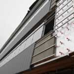
The practical consequence of this error showed up in post-Ian assessments of several Fort Myers Beach hospitality projects. In each case, the specification basis-of-design called out a high-impact assembly with 20 oz/sq yd mesh and a minimum 3/16-inch base coat thickness.
The substitution language required only that the alternative system use “equivalent or heavier mesh. ” Approved substitutions came in with 15 oz/sq yd mesh in a dual-layer configuration that the substituting manufacturer claimed was equivalent by weight.
The dual-layer configuration had not been tested as a unit under ASTM E695 to the same classification. The assemblies passed visual inspection at rough-in.
They did not perform equivalently under impact loading from wind-borne debris.
ICC-ES AC219 high-impact classification requires the assembly to resist a 90 ft-lb impact without cracking through the base coat to the substrate. Standard impact classification requires resistance to a 25 ft-lb impact.
Those are not interchangeable performance levels and the mesh weight alone does not determine which classification an assembly achieves. The base coat formulation, thickness and cure schedule all contribute to the tested result.
A specification that reduces impact resistance requirements to a single material property metric is not a performance specification; it is an invitation to substitution that the specifier cannot evaluate without retesting.
Drainage-Plane Design: The Detail Decisions That Determine Field Performance
Drainage-plane EIFS is the only system type that should be specified in high-wind coastal markets. Barrier EIFS, which relies on the lamina as the sole line of defense against water intrusion, has no acceptable role on a commercial building in Exposure Category C or D.
The drainage plane must be a continuous, uninterrupted path from the top of the wall assembly to weep screeds at the base.
Interruptions at penetrations, transitions and shelf angles are where failures originate. Through-wall flashing at horizontal terminations including windows, doors, shelf angles and roof-wall intersections must be integrated with the drainage plane using compatible materials.
Florida Product Approval is issued for a tested assembly configuration; deviating from the manufacturer’s published details, even slightly, technically voids the approval. That is not a technicality.
It is the entire basis on which the system passed testing.
Weep screed placement deserves more attention than it gets. Weep screeds must be positioned at every horizontal termination where water could accumulate, not just at the base of the wall.
This includes above window and door heads, above shelf angles and at floor-line transitions on multi-story assemblies. Blocking a weep screed with sealant, which happens regularly in the field when installers are trying to meet air barrier continuity requirements, converts a drainage-plane system into a barrier system at that location.
The water control layer in a drainage-plane EIFS assembly is the fluid-applied or sheet-applied WRB behind the insulation board, not the lamina. The lamina is the first line of defense; the WRB is the control layer.
Specifiers who treat the lamina as the primary water barrier are misunderstanding the system’s fundamental design intent and that misunderstanding shows up in the detailing.
The drainage mat or textured surface on the back face of the insulation board that creates the drainage cavity is a component that specifiers frequently treat as interchangeable between manufacturers. It is not.
Drainage cavity depth, mat compressibility under fastener load and compatibility with the fluid-applied WRB all vary by manufacturer and affect drainage efficiency under the hydrostatic pressure conditions that develop during sustained wind-driven rain events. ASTM E2273 defines the test method for drainage efficiency of exterior insulation and finish systems; a drainage efficiency rating of 90 percent or higher is the threshold that most building envelope consultants specify for coastal applications.
That number should appear in the specification, not just in the consultant’s report.
Shelf angle conditions on multi-story commercial construction represent the single highest-risk detail in coastal EIFS assemblies. The shelf angle interrupts the drainage plane, creates a horizontal surface where water accumulates and introduces a structural attachment that penetrates the WRB.
The through-wall flashing at the shelf angle must slope to drain, must extend beyond the face of the insulation board and must be integrated with the WRB using a compatible flashing tape or fluid-applied transition membrane. The EIFS insulation board above and below the shelf angle must be terminated with compatible accessories that maintain drainage continuity across the interruption.
Specifying “flash per manufacturer recommendations” at shelf angles is not adequate. The detail must be drawn, the materials must be named and the sequence of installation must be specified explicitly.
Air Barrier Continuity in High-Wind Assemblies: The Overlooked Failure Mode
Wind-driven water intrusion gets most of the post-hurricane attention, but air pressure differential is the mechanism that drives water through an assembly under hurricane conditions. An EIFS assembly with a compromised air barrier will experience pressure-driven infiltration at every imperfection in the lamina, regardless of how well the drainage plane is designed.
IBC 2021 Section 1404.3 references ASTM E2357 as the test method for air leakage resistance of exterior wall assemblies. Specifiers in high-wind markets should be requiring EIFS assemblies that have been evaluated under ASTM E2357 and should be confirming that the air barrier component, whether fluid-applied, self-adhered or mechanically attached, has been tested as part of the assembly rather than as a standalone product.
Continuity at fenestration rough openings is the most common air barrier failure point. The transition from the WRB to the fenestration frame must be detailed with compatible materials and must be explicitly specified; “flash and seal per manufacturer recommendations” is not a specification.
It is an abdication of the specifier’s responsibility. Name the flashing tape, name the sealant, specify the lap sequence and specify the sequence of operations.
The physics of pressure-driven infiltration under hurricane conditions are worth understanding in detail because they explain why air barrier failures produce water intrusion damage that drainage-plane design alone cannot prevent. During a hurricane, wind pressure on the windward face of a building creates positive pressure against the exterior cladding.
Simultaneously, suction on the leeward face and roof creates negative pressure on the interior side of the assembly. The resulting pressure differential across the wall assembly can exceed 30 psf on a Risk Category II commercial building in a 170 mph wind zone.
Any discontinuity in the air barrier, a missed lap at a WRB seam, an unsealed penetration sleeve, a flashing tape that delaminated from a wet substrate, allows air to move through the assembly under that pressure differential. Air moving through the assembly carries water with it and that water bypasses the drainage plane entirely because it is not flowing by gravity; it is being driven by pressure.
ASTM E2357 tests the assembly at 1.57 psf differential pressure, which corresponds to a 75 mph wind speed. That is the code minimum threshold.
For projects in the 160 to 185 mph Vult range, specifiers should be discussing with the building envelope consultant whether a higher test pressure threshold is appropriate for the basis-of-design system selection. Some manufacturers have tested their assemblies at higher pressures as part of Florida Product Approval testing and that data is available in the FPA documentation.
Requesting it is not an unusual ask; it is the kind of due diligence that distinguishes a coastal specification from a generic one.
The sequencing of air barrier installation relative to other trades is a specification and coordination issue that produces more field failures than any single material selection decision. Fluid-applied WRBs require a minimum substrate temperature and maximum moisture content for proper adhesion and film formation.
In coastal Florida construction schedules, where concrete masonry substrates may be exposed to rain and high humidity for weeks before the EIFS applicator mobilizes, confirming substrate conditions at the time of WRB application is not optional. The specification should require substrate moisture testing, define the acceptable moisture content threshold and assign responsibility for testing to a named party.
Leaving that responsibility unassigned guarantees it will not happen.
Thermal Performance Under Coastal Conditions: Effective R-Value Is Not Nominal R-Value
Continuous insulation in EIFS assemblies delivers thermal performance that other cladding systems struggle to match at equivalent installed cost. In IECC Climate Zone 2 (coastal Florida and Gulf Coast markets), ASHRAE 90.1-2022 Table A2.
3 requires specific effective R-value targets for above-grade walls in commercial occupancies. EIFS with 3 to 4 inches of EPS routinely meets or exceeds these targets without the thermal bridging penalties that steel-stud assemblies with batt insulation carry.
Effective R-value is the number that matters for code compliance and energy modeling; nominal R-value of the insulation board alone is not the correct metric. Cladding attachment brackets and shelf angles create point and linear thermal bridges that reduce effective R-value below nominal.
In EIFS assemblies, the insulation is the substrate and mechanical attachment to the framing is typically limited to the base track and termination conditions, which substantially reduces the bridging penalty compared to bracket-attached cladding systems.
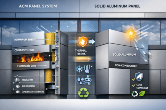
The tradeoff worth naming directly: EPS-based EIFS requires careful detailing at fire-rated wall assemblies. IBC Section 2603.5 governs foam plastic insulation in exterior walls and requires specific thermal barrier provisions.
Specifiers must confirm that the EIFS assembly configuration used in fire-rated wall construction matches the tested assembly exactly, including insulation thickness and density.
The energy modeling implications of effective R-value versus nominal R-value are significant enough to affect compliance outcomes on projects where the wall assembly is a meaningful contributor to the overall building envelope thermal performance calculation. A 3.5-inch EPS board has a nominal R-value of approximately R-14. The same assembly installed over a steel stud framing system with base tracks at 48 inches on center, shelf angles at each floor line and