


EIFS in Commercial Construction: Where the System Fails and How Modern Detailing Addresses the Root Causes
A mid-rise medical office building in the Mid-Atlantic region, clad in barrier EIFS installed in 2009, required full facade remediation by year eleven. The lamina had not delaminated.
- EIFS in Commercial Construction: Where the System Fails and How Modern Detailing Addresses the Root Causes
- Why EIFS Keeps Ending Up in Litigation Despite Decades of Refinement
- Barrier EIFS vs. Drainage EIFS: A Classification That Determines Risk Profile
- The Five Detailing Deficiencies Most Responsible for EIFS Moisture Failures
- How Drainage EIFS Assemblies Manage the Risks Barrier Systems Cannot
- Transition Detailing at Dissimilar Materials: Where Specifications Consistently Fall Short
- What Current Code and Standards Require Versus What Best Practice Recommends
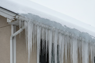
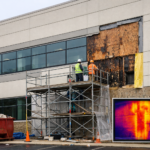
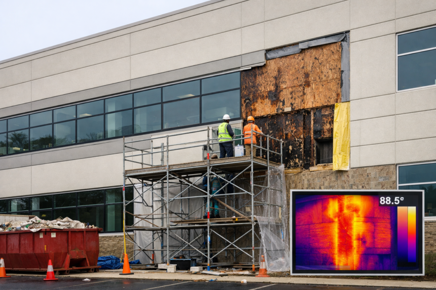
The insulation board had not failed. A single continuous sill flashing was omitted at a ribbon window assembly spanning three bays and the resulting moisture intrusion rotted the OSB sheathing behind 40 linear feet of facade before thermal imaging identified the anomaly during a routine commissioning audit.
The remediation cost exceeded the original EIFS contract value by a factor of three. That ratio is not unusual.
What is unusual is that anyone was surprised.
Why EIFS Keeps Ending Up in Litigation Despite Decades of Refinement
EIFS carries one of the highest construction defect claim rates per installed square foot among commercial cladding systems in North America. Insurance carrier loss data and EIFS Industry Members Association (EIMA) survey figures consistently place installation and detailing deficiencies as the responsible factor in more than 80 percent of documented failures.
Product defects account for a small fraction of claims. The system itself is not the problem.
Forensic investigations across hundreds of commercial and institutional projects point to the same three failure zones with striking consistency: transitions and terminations, penetrations through the lamina and base-of-wall conditions. These are not obscure or difficult details.
They appear in every manufacturer’s installation guide and in EIMA’s published guideline specifications. They fail anyway, because the specification-to-field gap in EIFS work is wider than most architects acknowledge at the design phase.
That gap has a specific anatomy. The architect produces a wall section at a scale that cannot resolve a sill flashing leg dimension.
The project manual references the manufacturer’s installation guide by title without incorporating its specific flashing requirements into the construction documents. The EIFS installer bids the work based on the drawing set, not the manufacturer guide the drawing set references.
The fenestration installer sequences their work without a pre-installation meeting that would have identified the conflict. Each party performs their scope in isolation and the water control layer ends up discontinuous at exactly the location where continuity is most critical.
The litigation record reflects this pattern. Claims rarely turn on whether the correct product was specified.
They turn on whether the specified assembly was actually built and on whether the design documents were detailed enough to define what “correctly installed” meant at the specific conditions where failures occurred. Expert witnesses in EIFS litigation spend the majority of their time at transitions, terminations and penetrations, not at field conditions where the lamina is intact and the installation is straightforward.
The thesis here is direct: EIFS is a capable cladding system with a well-documented liability record that traces almost entirely to decisions made at the drawing board and on the scaffold, not to the material itself.
Barrier EIFS vs. Drainage EIFS: A Classification That Determines Risk Profile
Barrier EIFS relies entirely on the lamina, the composite assembly of base coat, reinforcing mesh and finish coat, as the sole water-resistive layer. There is no drainage plane behind the insulation board.
The system assumes the lamina remains intact and continuous indefinitely. That assumption fails in practice through sealant joint aging, impact damage and micro-cracking at substrate transitions.
Drainage EIFS incorporates a drainage medium behind the insulation board, directing incidental moisture that bypasses the lamina to a flashed exit point at the base screed. ASTM E2568, the current Standard Specification for PB Exterior Insulation and Finish Systems, formally differentiates between the two classifications and establishes performance criteria for each.
The distinction is not cosmetic. It represents a fundamentally different premise about how the assembly manages water as the four control layers age.
The 2021 IBC addresses this directly. Section 1403.2 requires weather protection for exterior walls and Section 1407, which contains EIFS-specific provisions, tightens drainage plane continuity requirements for cladding systems on wood-framed and light-gauge steel substrates.
On wood-frame construction, drainage EIFS is effectively the code-compliant default in jurisdictions that have adopted the 2021 edition. Specifying barrier EIFS on a wood-frame mid-rise today is not just a performance risk.
It is a code compliance question that requires a documented answer.
The service life argument reinforces the code argument. Sealant joints in commercial EIFS assemblies have a realistic service life of ten to fifteen years under normal UV exposure and thermal cycling conditions.
A building with a fifty-year design life will require at least two complete sealant replacement cycles. During each replacement cycle and during the period of deferred maintenance that typically precedes it, the lamina is not performing as a barrier.
Incidental moisture is entering the assembly. In a barrier system, that moisture has nowhere to go except into the substrate.
In a drainage system, it exits at the base screed. That difference in outcome is the entire performance argument for drainage EIFS and it does not require a catastrophic lamina failure to become consequential.
It requires only the ordinary aging of a sealant joint and the absence of a managed drainage path.
The Five Detailing Deficiencies Most Responsible for EIFS Moisture Failures
Missing or discontinuous sill flashing at fenestration heads and sills is the single most frequently cited failure mode in EIFS forensic reports. When through-wall or pan flashing is absent, water that bypasses the lamina at the sill joint has no managed exit path.
It migrates laterally into the assembly, saturating sheathing and framing over months before any interior evidence appears. The medical office case in the opening is not exceptional.
It is representative.
The specific geometry of sill flashing in EIFS assemblies creates a coordination problem that generic details do not resolve. The pan flashing must slope to drain, terminate at end dams that turn up behind the window frame and integrate with the WRB at its back leg.
The front leg must extend to the exterior face of the EIFS lamina and terminate with a drip edge that prevents capillary wicking back into the assembly. When the fenestration installer sets the window before the EIFS installer has established the WRB plane, the back leg integration becomes physically impossible without removing and resetting the window unit.
That sequencing conflict is predictable. It is also rarely addressed in the project schedule or the pre-installation meeting that most projects do not hold.
Inadequate base-of-wall termination is the second most common deficiency. EIFS terminated at or below grade, at horizontal ledges or without a proper drip screed and sealant joint creates conditions for capillary wicking and splash-back intrusion.
The base of the assembly is where gravity-driven water concentrates. Treating it as a secondary concern is a documented path to substrate damage.
EIMA guidelines specify a minimum two-inch clearance between the base screed and any horizontal surface, including grade, paving, roof membranes and horizontal ledges. That clearance is routinely compromised by finish grading that occurs after the EIFS installation is complete, by paving contractors who do not know the clearance requirement exists and by landscape contractors who install planting beds against the base of the wall.
The EIFS installer completes their scope correctly. The clearance disappears six months later.
The specification that addresses this condition requires not just a correct base detail but a note on the civil and landscape drawings that identifies the clearance requirement as a coordination item.
Unsealed or improperly detailed penetrations represent the third failure category. Every pipe, conduit, scupper, signage anchor and mechanical sleeve that passes through the lamina without a correctly sized backer rod and compatible sealant, with joint geometry that meets ASTM C1193 depth-to-width ratios, creates a direct water pathway.
These penetrations multiply over a building’s service life as tenants and operators add equipment. The original installation may be clean.
The five-year-old conduit penetration installed by an electrical subcontractor with no envelope awareness is not.
ASTM C1193 establishes that sealant joint depth should equal half the joint width for joints up to one-half inch wide, with a minimum depth of one-quarter inch. Field penetrations through EIFS lamina are rarely circular holes of consistent diameter.
They are frequently irregular openings cut with a utility knife or a hole saw, with gaps that vary around the perimeter of the penetration sleeve. Backer rod selection for these conditions requires matching the rod diameter to the actual gap dimension, not to a nominal sleeve size.
The specification should require the installing contractor to measure and document penetration gap dimensions before sealant application. That requirement is almost never written into project specifications and the result is sealant joints that are either too shallow to perform or bridging across gaps too wide for the joint geometry to accommodate movement.
Expansion and control joint omission or misplacement is the fourth deficiency. EIMA guideline specifications establish maximum field panel dimensions and joint spacing requirements tied to substrate type and geographic location.
Joints omitted at floor line transitions, at changes from steel to wood framing or at re-entrant corners allow differential movement to crack the lamina at predictable locations. The crack is not random.
The forensic investigator finds it exactly where the joint should have been.
The specification-to-field failure at control joints typically takes one of two forms. Either the joint locations are not shown on the construction documents and the installer places them based on their own judgment or the joint locations are shown schematically but without the dimensions, sealant designation and backer rod specification needed to build them correctly.
A joint shown on a drawing at a scale of one-eighth inch per foot communicates location. It does not communicate the one-half inch minimum width, the polyurethane sealant by ASTM C920 Type S Grade NS Class 25 designation or the closed-cell backer rod diameter that the joint requires to perform.
That information belongs in the specification and on a large-scale detail. When it is absent, the installer makes a judgment call and the judgment call is frequently wrong.
WRB integration failures at the sheathing level complete the list. Reverse laps, unsealed seams and failure to integrate the WRB with fenestration flanges and flashing components undermine the secondary drainage plane in drainage EIFS assemblies.
ASTM E331 water penetration testing, the benchmark method used in forensic investigations to confirm failure locations under controlled pressure differentials, reliably identifies these integration failures when the assembly is tested in situ. The test does not lie.
The detail did.
How Drainage EIFS Assemblies Manage the Risks Barrier Systems Cannot
The physics argument for drainage EIFS is straightforward. Even a correctly installed barrier EIFS will experience incidental moisture intrusion over time.
Sealant joints have finite service lives. Lamina micro-cracking occurs at substrate transitions under thermal cycling.
Impact damage from maintenance equipment is routine on commercial facades. Drainage EIFS accepts these premises as engineering reality and provides a managed exit path rather than pretending the lamina is permanently impermeable.
Three drainage medium configurations appear in current commercial practice. The first uses grooved channels cut into the face of the EPS board, creating a network of vertical drainage pathways directly behind the insulation.
The second uses a factory-applied drainage mat laminated to the EPS board face, typically a three-dimensional polymer mesh that maintains an air gap. The third uses a separate drainage-capable WRB installed between the sheathing and the EPS, such as a crinkled or channeled housewrap product tested to ASTM E2570, the Standard Test Method for Water-Resistive Barrier Coatings Used with EIFS.
Each configuration carries a different set of field execution requirements that the specification must address explicitly. Grooved EPS board must be installed with the channels oriented vertically and continuous from the base screed to the termination point at the top of the assembly.
Horizontal cuts through the channels, such as those made to fit the board around a shelf angle or a horizontal ledge, interrupt the drainage path and require a flashing component to redirect water to the exterior. Factory-applied drainage mats must be lapped and sealed at board joints to prevent the mat from acting as a horizontal water distribution layer rather than a vertical drainage layer.
Drainage-capable WRBs must be installed with the drainage channels oriented vertically, which requires the installer to identify the correct orientation from the product markings before the board is adhered. These are not details that a generic specification resolves.
They require product-specific installation requirements incorporated into the project specification by reference to the manufacturer’s current installation guide, with the guide edition date identified to prevent the contractor from substituting an older version.
All three configurations share one non-negotiable requirement: the drainage medium must connect uninterrupted to a flashed and open exit at the base screed. A drainage EIFS assembly with a blocked base screed or an unflashed termination performs no better than a barrier system.
The drainage plane becomes a collection plane. That outcome is documented in field investigations and it is entirely preventable through correct detailing at the one location where the drainage medium must terminate.
Under 2021 IBC Section 1407.3, drainage EIFS on wood-frame construction is not a best practice recommendation. It is a code requirement in jurisdictions that have adopted the current edition.
Transition Detailing at Dissimilar Materials: Where Specifications Consistently Fall Short
The most technically demanding EIFS details occur where the system meets a different cladding material, a structural element or a substrate change. These transitions concentrate stress, interrupt the WRB continuity and require coordination between trades that rarely share a pre-installation meeting.
They are also where specifications most often fail to provide adequate direction.
At shelf angles and floor-line conditions on concrete or steel-frame construction, the EIFS assembly must terminate, allow for differential movement between the structural frame and the cladding and resume without creating a direct water pathway. The sealant joint at this location must accommodate both in-plane and out-of-plane movement.
Specifying a sealant without identifying the movement capacity required or detailing a joint width that cannot accommodate the actual differential, produces a cracked joint within two to three thermal cycles.
Calculating the required joint width at a shelf angle condition requires knowing the anticipated differential movement between the structural frame and the EIFS assembly. On a steel-frame building in a northern climate, the differential between the steel frame and the EPS-based cladding over a temperature range of 150 degrees Fahrenheit can exceed one-quarter inch per story height.
A joint detailed at three-eighths inch width with a sealant rated for plus or minus 25 percent movement has a total movement capacity of approximately three-sixteenths inch. That joint will fail.
The calculation is not complex. It requires the designer to perform it and record the result on the construction document rather than defaulting to a standard joint width that may have no relationship to the actual movement demand at that specific condition.
At transitions to dissimilar cladding materials, the WRB must lap correctly behind both systems and terminate at a flashing that directs water to the exterior face of the outermost cladding material. When EIFS meets a brick veneer, a metal panel system or a glazed curtainwall, the flashing geometry at the transition is rarely standard.
It requires a project-specific detail. Generic details from manufacturer literature do not address the specific geometry of a given facade composition.
A transition from EIFS to a rainscreen metal panel system illustrates the coordination requirement. The metal panel system’s WRB and the EIFS system’s WRB must lap at the transition in a configuration that directs water toward the exterior face of whichever cladding occupies the lower position at the transition.
If the metal panel system is below the EIFS, the EIFS WRB must lap over the metal panel WRB at the transition flashing. If the EIFS is below the metal panel, the metal panel WRB must lap over the EIFS WRB.
The flashing at the transition must be mechanically fastened, sealed at its back leg to the WRB of the upper system and terminated with a drip edge at its front leg. That sequence requires the two cladding installers to coordinate their WRB installations at the transition before either system’s cladding components are installed.
On most projects, that coordination meeting does not happen and the transition is built in the sequence that is most convenient for the first trade on site.
The specification-to-field gap is widest at these conditions. The architect draws a schematic transition.
The EIFS installer interprets it based on prior practice. The result is frequently neither what the drawing intended nor what the code requires.
What Current Code and Standards Require Versus What Best Practice Recommends
The 2021 IBC and ASTM E2568 establish minimum performance thresholds. They do not define best practice and conflating the two produces assemblies that pass code review and fail in service.
Code requires drainage EIFS on wood-frame construction under 2021 IBC Section 1407.3. Best practice specifies drainage EIFS on all substrate types in IECC Climate Zones 4 through 7, where freeze-thaw cycling accelerates sealant degradation and lamina micro-cracking. The reasoning is straightforward: a concrete masonry or steel stud substrate does not rot, but it can still accumulate moisture at the interface between the substrate and the insulation board, leading to corrosion of metal fasteners and framing components, freeze-thaw spalling of masonry and degradation of adhesive bond between the EPS board and the substrate.
The drainage plane addresses all of these failure modes regardless of substrate type. Limiting the drainage EIFS requirement to wood-frame construction, as the code does, reflects a minimum threshold based on the most damage-susceptible substrate.
It does not reflect the full range of conditions under which a drainage plane improves long-term assembly performance.
Code requires fenestration integration with the WRB. Best practice specifies a self-adhered flashing membrane at all sill and jamb conditions, lapped correctly into the WRB, with a sloped sill pan that dr